Note : Les descriptions sont présentées dans la langue officielle dans laquelle elles ont été soumises.
CA 02430538 2003-05-30
Can crusher apparatus and method
Detailed description of a preferred embodiment
The can crusher apparatus operates in a continuous mode to cxush or compress
cans or small
containers of different sizes and shapes, such that the cans or containers are
emptied from
their contents and therefore reduced to a configuration which greatly improves
their ability to
be recycled.
In order to be recycled, cans and containers must conform to strict
environmental norms
which regulate, among other things, the list of materials and substances which
can be xecycled
and the state into which they can be reintroduced into the recycling loop.
Prior to being
recycled, cans and containers may contain multiple types of products in
liquid, solid or even
gaseous states. When they are recycled, such cans and containers usually still
contain
leftovers of their original contents.
Paint cans represent the prime interest of this invention, but the principles
behind this
invention are applicable to multiple types of other containers which can be
recycled.
The apparatus includes an introduction area, a crushing axea, a recuperating
area, a
compression area and an exit area. Throughout a cycle in the apparatus, each
can more or less
follows a path which progressively and continuously transforms it from its
original shape to a
crushed state.
The introduction area represents the location where the cans are placed in the
apparatus,
waiting to be crushed. .Amongst different types of configurations which may be
used in the
introduction area, the apparatus may include a magazine type dispenser or a
manual feed
system with a conveyor.
The cans preferably arrive at the introduction area with one of its
extremities removed, either
the bottom or the cover of the can, or otherwise the can includes at least an
opening to
facilitate the extraction of the paint or other substances remaining inside
the can as it goes
through the apparatus. In another embodiment, the apparatus comprises another
sub-system,
I
CA 02430538 2003-05-30
physically located before or after the introduction area to remove the bottoms
or the covers of
the cans or to perform the required openings on at least one of the surfaces
of the can.
The cans are introduced in the introduction area with ox without a specific
orientation but
preferably, with its opened area facing upward, and preferably leave it with a
controlled and
pre-selected orientation. In the preferred embodiment, the cover of the can is
removed and the
can enters the introduction area with its opening facing upward and its bottom
(or closed
surface) resting on a conveyor or other carrying means. However, other can
introducing
orientations may be used with this invention and will be further described
hereinafter.
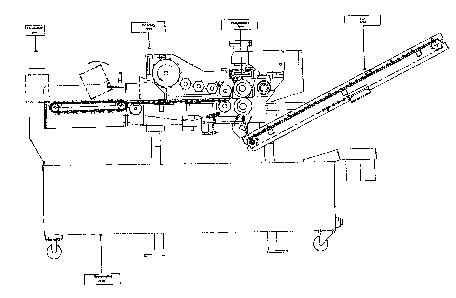
A guide is located at the junction of the introduction and crushing areas in
order to flip the
cans, if necessary, in the appropriate orientation for the crushing area, as
illustrated in figure
1. When the can's upper edge or side surface starts interfering with the
guide, the can is
flipped along a lateral direction, such that its cylindrical or side surface
now rests on the
conveyor and that its bottom surface faces the crushing area. The apparatus
also includes
lateral supports where the flip of the can takes place, to ensure that the
cans keep an adequate
longitudinal positioning after being flipped on their side.
The crushing area comprises tu~o adjacent and cooperating members working in
conjunction.
The spacing between the adjacent members defines a generally longitudinally
extending
passage for the cans. In the preferred embodiment, the first cooperating
member consists of a
longitudinally extending conveyor, preferably located beneath the second
cooperating
member. The first member acts as the can's support and carrier as soon as it
leaves the
introduction area.
Among the various types of known conveyors, the "table top conveyor" is
preferably selected
since it offers an almost continuous carrying surface, which usually ensures
greater stability to
the objects placed on the conveyor. In the embodiment presented hereinabove,
the can has
been flipped before entering the crushing area such that the can's side
surface rests on the
"table top conveyor", or table. The table therefore provides a carrying
surface to the cans in
this cycle of the apparatus. The can's first moments in the crushing area does
not yet involve
the second member, even if the can is engaged in the spacing defined by the
two adjacent
members.
2
CA 02430538 2003-05-30
The second member is preferably a roll type conveyer, or a series of rolls,
which are
controlled and operated independently from the table. The rolls are preferably
laterally
extending and longitudinally located next to one another such that a "working
surface" is
defined above the carrying surface of the table. This working surface is
located at an angle
with respect to the table. The angle is such that the highest distance between
the working
surface and the carrying surface is near the entry of the crushing area. In
the preferred
embodiment, that angle does not have to be set-up, but the crushing area can
comprise a
angular control to orient the rolls for other modes of operation of the
apparatus, for other size
or types of cans to be crushed or to get another desired crushing condition.
Each can progressively engages in the spacing between the tal3le and the
rolls, on the carrying
surface. The carrying surface of the table advances without interference
toward the
compression area, at a pre-determined speed, until the can's edge of its
closed portion gets
closer to the working surface of the rolls. The rolls rotate in an opposite
direction than the
I S rotation direction of the conveyor, at a predetermined speed, which is
preferably different than
the carrying surface of the table.
If the apparatus is viewed from a lateral view (see figure I) and that the
table rolls in a
clockwise direction, the can which is carried by the carrying surface is moved
in a generally
right-hand direction. The rolls roll in a counterclockwise direction such that
the working
surface directly facing the carrying surface also moves in a generally right-
hand direction
(with a vertical component due to its angularity).
At that time, the can does not yet interfere with the angled working surface.
The can therefore
continues to be carried by the carrying surface toward the compression area
and, in this
embodiment, in a right-hand side direction. When the bottom surface's edge
interferes with
the angled working surface, the can is progressively crushed by a shear force.
In a preferred embodiment, the table operates at a highex speed than the
roll's speed. The
crushing operation starts where the bottom of the can is in contact with the
working surface,
because the bottom portion of the can resting on the carrying surface goes at
a higher speed
than the bottom portion of the can in contact with the working surface.
3
CA 02430538 2003-05-30
The can is progressively crushed and as a result, any remaining paint or other
substances are
progressively squeezed out of the can, from the closed or preferably bottom
surface, up to the
opening of the can. Paint is therefore progressively forced out, from the
closed end to the
open end of the can.
In most prior art crushing systems, the can is usually compres sed along its
axial direction and
usually comprise a hole near its top or bottom to provide an exit to any
remaining contents. In
those cases however, multiple circumferentially extending pockets, grooves or
recesses are
generated on the can's cylindrical or side surface as it gets crushed, such
that paint or other
substances in the can may accumulate and get stuck in those pockets during the
crushing
process. The pockets also significantly impair the goal of achieving the
optimal crushing
thickness of the cans, since even a "completely" crushed can using such prior
art devices still
includes a plurality of pockets, grooves or recesses located on top of one
another and along
the circumference of the cans.
The progressive shear force crushing process and the specific can positioning
provided by the
apparatus of our invention significantly reduces the occurrences of pockets in
the crushed can,
such that the final thickness of the can and the residual quantities of paint
or other substances
inside the can is minimized.
The distance between the working surface and the carrying surface is at its
minimum near the
exit of the crushing area. In another embodiment, this distance can be
adjusted and pre-
selected for various types of cans in order to put them in a desired pre-
crushed state (before
the can enters the compression area), with a certain thickness and such that a
large portion of
paint has had a chance to be removed.
The recuperating area is located in the vicinity of the introduction area, the
crushing area, the
compression area and the exit area. As paint or other substances starts being
expelled from the
can at its opening, it is recuperated in the recuperating area, which can be
any type of
container connected to the apparatus and also preferably located underneath
and aligned with
the vertical projection of the areas mentioned hereinabove.
After leaving the crushing area, the pre-crashed can enters the compression
axea. As shown in
Figure l, the compression area includes at Least two generally parallel and
laterally rotating
4
CA 02430538 2003-05-30
toothed rolls. The toothed rolls are preferably located one on top of the
other and vertically
aligned to be complementary. If more than two toothed rolls are used, they are
longitudinally
located in rows for complementary.
Each toothed roll comprises gear type section profiles which are repeated
along its lateral
length. The teeth numbers, the size and the shape of the section profiles
depends on the
distance between the upper and lowex toothed rolls, the desired compression
effect of the can
in the compression area and the fact that the can still needs to be moved out
of the apparatus,
which requires a friction and/or "meshing" grip on the can. Any other teeth or
surface
configuration of those rolls providing the advantages stated herein could be a
substitute to the
toothed rolls.
By rotating in opposite directions (the lower toothed roll rotates in a
clockwise direction and
the upper toothed roll rotates ire a counter-clockwise direction in Figure 1)
the rolls "mesh"
with the crushed can in the middle along the compression area, for a final
compression stage.
According to the hereinabove described embodiment, the toothed rolls
participate in
compressing the pre-crushed can to its desired final thickness and to carrying
the crushed can
in a right-hand direction, toward the exit area.
The "meshing" of corresponding toothed rolls does not physically implicate the
complete
entry of one toothed roll's tooth inside a cavity in between consecutive teeth
in the other
toothed roll, but rather acts like claws, at a pre-selected distance from one
another "gripping"
on the crushed can and doing a final compression process.
The level of compression is ensured by the distance between the upper and
lower rolls. In one
embodiment, the upper rolls are connected to a spring system offering an
adaptable thickness
control of the can going through the compression area.
Any remaining paint is squeezed out from the can at the beginning of the
compression area
and falls in the recuperating area. The compression area therefore effectuates
the final
compression of the can with a minimum amount of paint residually left on the
toothed rolls.
5
CA 02430538 2003-05-30
At the end of the compression area, the upper and lower rolls automatically
push the crushed
can to the exit area, which could be any type of container or space for
reception of the crushed
cans.
The apparatus operates in a continuous mode which does not rE;quire constant
repositioning of
the can during its sojourn in the apparatus. Therefore the estimated duration
of a cycle
bettveen the moment where a can leaves the introduction area to the moment
where the can
enters the exit area can be approximately 5 seconds.
For maintenance of the apparatus, a plurality of fixed and laterally extending
scrapers are
located near the rolls or any other surface, like conveyors, where paint or
other substances can
be accumulated and not fall in the recuperating area. For cumbersome or
difficult access
areas, mobile scrapers are located in the vicinity of some components of the
apparatus where
paint may need to be removed.
Also, another embodiment of the apparatus includes a mechanism, automated or
not, which
allows the upper roll in the compression area to be temporarily separated from
the lower roll
in order to minimize the quantity of debris tike paint or other substances to
be stuck at the
entry of the compression area. This operation can be introduced after each can
has gone
trough a full cycle in the apparatus.
6