Sélection de la langue

Search

Sommaire du brevet 2430605 

Énoncé de désistement de responsabilité concernant l'information provenant de tiers

Une partie des informations de ce site Web a été fournie par des sources externes. Le gouvernement du Canada n'assume aucune responsabilité concernant la précision, l'actualité ou la fiabilité des informations fournies par les sources externes. Les utilisateurs qui désirent employer cette information devraient consulter directement la source des informations. Le contenu fourni par les sources externes n'est pas assujetti aux exigences sur les langues officielles, la protection des renseignements personnels et l'accessibilité.

Disponibilité de l'Abrégé et des Revendications

L'apparition de différences dans le texte et l'image des Revendications et de l'Abrégé dépend du moment auquel le document est publié. Les textes des Revendications et de l'Abrégé sont affichés :

  • lorsque la demande peut être examinée par le public;
  • lorsque le brevet est émis (délivrance).
(12) Brevet: (11) CA 2430605
(54) Titre français: RESSORT HYDRAULIQUE AVEC AMORTISSEUR
(54) Titre anglais: HYDRAULIC SPRING HAVING A DAMPER
Statut: Réputé périmé
Données bibliographiques
(51) Classification internationale des brevets (CIB):
  • F16F 13/10 (2006.01)
(72) Inventeurs :
  • GEDENK, VOLKER (Allemagne)
(73) Titulaires :
  • CONTITECH LUFTFEDERSYSTEME GMBH (Allemagne)
(71) Demandeurs :
  • CONTITECH LUFTFEDERSYSTEME GMBH (Allemagne)
(74) Agent: BORDEN LADNER GERVAIS LLP
(74) Co-agent:
(45) Délivré: 2010-02-23
(86) Date de dépôt PCT: 2001-12-15
(87) Mise à la disponibilité du public: 2002-07-04
Requête d'examen: 2006-10-11
Licence disponible: S.O.
(25) Langue des documents déposés: Anglais

Traité de coopération en matière de brevets (PCT): Oui
(86) Numéro de la demande PCT: PCT/EP2001/014847
(87) Numéro de publication internationale PCT: WO2002/052168
(85) Entrée nationale: 2003-05-30

(30) Données de priorité de la demande:
Numéro de la demande Pays / territoire Date
100 64 762.6 Allemagne 2000-12-22

Abrégés

Abrégé français

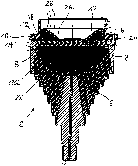
Le volume hydraulique (4a, 4b) d'un ressort hydraulique est, d'une part, ferm~ par un ~l~ment ~lastique (b) qui est form~ par vulcanisation dans une bague ext~rieure (8), et, d'autre part d~limit~ par une membrane de compensation (10). Ledit volume (4a, 4b) est divis~, par une paroi de s~paration (26) comportant au moins un canal de liaison (28), en deux chambres (4a, 4b) ~ volume variable, remplies compl­tement d'un liquide hydraulique. Pour que l'on obtienne un ~l~ment amortisseur pr~sentant un faible encombrement en hauteur, la paroi de s~paration (2b) est de forme plane, ses plans ~tant orient~s transversalement par rapport ~ l'axe du ressort. A l'int~rieur de la paroi de s~paration (26) plane s'~tend au moins un canal de liaison (28) plan. De pr~f~rence, le canal de liaison ou les canaux de liaison (28) ont une forme h~lico~dale. Plusieurs canaux de liaison (28) de forme h~lico~dale peuvent Útre dispos~s dans la paroi de s~paration (26) en ~tant d~cal~s l'un par rapport ~ l'autre.


Abrégé anglais


A hydraulic spring includes hydraulic volumes (4a, 4b). The
hydraulic volumes (4a, 4b) are, on the one hand, closed off by a
spring element (6) which is vulcanized into an outer ring (8).

On the other hand, the volumes (4a, 4b) are delimited by a
compensating membrane (10). The volume (4a, 4b) is subdivided by
a partition wall (26) into two chambers (4a, 4b), namely, a work
chamber (4a), which is next to the spring element (6), and a

compensating chamber (4b), which is next to the compensating
membrane (10). The partition wall (26) has at least one
connecting channel (28) and the chambers (4a, 4b) alternately
change in volume and are filled completely with a hydraulic
liquid. The partition wall (26) is configured to be flat in
order to achieve a damping element requiring only a low
structural elevation. The partition wall plane is orientated
transversely to the spring axis. At least one level connecting
channel (28) extends within the flat partition wall (26). One
end of the connecting channel opens into the work chamber (4a)
and the other end of the connecting channel opens into the
compensating chamber (4b). The at least one connecting
channel (28) is preferably configured to have a spiral shape.
Several connecting channels (28) can be arranged offset relative
to each other in the partition wall (26) and these channels are
configured to have a spiral shape.

Revendications

Note : Les revendications sont présentées dans la langue officielle dans laquelle elles ont été soumises.


CLAIMS:

1. A hydraulic spring comprising:
a rubber elastic spring element defining a spring axis;
a highly flexible elastic compensating membrane;
said rubber elastic spring element and said compensating membrane conjointly
closing off a volume;
a partition wall partitioning said volume into a work chamber delimited by
said
spring element and a compensating chamber delimited by said elastic
compensating
membrane;
said chambers being changeable in volume and filled with hydraulic fluid;
said partition wall having a plurality of connecting channels arranged within
said
partition wall offset one with respect to the other to permit a flow of said
hydraulic fluid
between said chambers during the operation of said hydraulic spring said
connecting
channels being configured to have a spiral shape within said partition wall;
an outer ring vulcanized to said spring element;
said partition wall having a planar configuration and extending transversely
to
said spring axis;
said connecting channels extending planar-like within said partition wall and
having a first end opening into said work chamber and a second end opening
into said
compensating chamber; and
said partition wall including at least two discs lying one atop the other; at
least
one of said two discs having a spirally-shaped slot formed therein; and, said
spirally-
shaped slot defines said connecting channel when said two are in the assembled
state
one atop the other;
wherein said connecting channel has an inner surface formed so at to have a
coarse or a
fine structure to affect the flow characteristic of the hydraulic fluid
flowing therethrough
between said chambers.


2. The hydraulic spring of claim 1, wherein said connecting channels define
respective flow paths connected in parallel with each other.


6


3. The hydraulic spring of claim 2, wherein said plurality of channels is
disposed in
one or more planes within said partition wall.


4. The hydraulic spring of claim 1, wherein said partition wall comprises
first and
second discs lying one atop the other; said first and second discs having
first and second
slots formed therein to correspond to each other; said first and second slots
conjointly
defining said connecting channel when said first and second discs are mounted
one atop
the other; and, said first and second discs being rotatable relative to each
other so as to
change the effective cross-section of said connecting channel.


7

Description

Note : Les descriptions sont présentées dans la langue officielle dans laquelle elles ont été soumises.


Attorney Docket No: 200-106
Hydraulic Spring having a Damper

Field of the Invention

The invention relates to a hydraulic spring having a damper,
especially as a primary spring for use in rail vehicles as
disclosed in German patent 4,446,800 wherein the spring is
referred to as a "hydraulically damping elastic bearing".
Background of the Invention

The bearing, which is described in German patent 4,446,800
with respect to FIG. la thereof, includes a spring element 1
which, on the one hand, is connected to a connecting part 11 and,
on the other hand, is fixedly connected to a cylindrical

housing 3. The spring element 1 is especially vulcanized to the
cylindrical housing 3. The cylindrical housing 3 is secured with
threaded fasteners to the other connecting part 12. The

cup-shaped bearing cover 13 is connected as one piece to the
connecting part 12 and has air compensating bores 13.1. The
hydraulic damping system of the bearing comprises the work
chamber 6 and the compensating chamber 7 closed off to the

ambient by the highly flexible elastic compensating membrane 2 as
well as a connecting channel 4 formed in the partition wall 5.
The enclosed hydraulic liquid can flow throttled back and forth
through the connecting channel 4 between the two chambers.

According to the state of the art, the partition wall 5,
which is arranged within the elastic bearing, includes a
cylindrical edge surface in which a screw-shaped slot is formed.
Together with the housing 3, the slot, which is formed in the
cylindrical edge surface, forms a channel 4 which connects the
two hydraulic chambers 6 and 7 with each other.

The manufacture of the slot in the cylindrical edge surface
1
CA 02430605 2003-05-30


is relatively cost intensive. The cylindrical edge requires a
certain space in elevation for accommodating the same because of
its axial height and this height cannot be used as a path for
spring deflection. An adjustment of the damping to the

particular masses to be suspended is not possible with the known
connecting channel (damping channel 4).

Summary of the Invention

It is an object of the invention to further develop the
known hydraulic spring and it is especially an object of the
invention to provide a damping element which is cost effective

and requires a low structural elevation for accommodating the
same.

The hydraulic spring of the invention includes: a rubber
elastic spring element defining a spring axis; a highly flexible
elastic compensating membrane; the rubber elastic spring element

and the compensating membrane conjointly closing off a volume; a
partition wall partitioning the volume into a work chamber
delimited by the spring element and a compensating chamber
delimited by the elastic compensating membrane; the chambers

being changeable in volume and filled with hydraulic fluid; the
partition wall having at least one connecting channel to permit a
flow of the hydraulic fluid between the chambers during the
operation of the hydraulic spring; an outer ring vulcanized to
the spring element; the partition wall having a planar

configuration and extending transversely to the spring axis; and,
the connecting channel extending planar-like within the partition
wall and having a first end opening into the work chamber and a
second end opening into the compensating chamber.

According to a feature of the invention, a damping channel
is disposed in a single plane arranged transversely to the spring
2
CA 02430605 2003-05-30


axis. From this, a very low structural elevation results, that
is, either the structural elevation, which is needed for damping
channels, can be used for an expanded spring path or, for the
same spring path, the spring can be constructed overall to be

smaller.

An adequate flow length can be realized by a spirally-shaped
configuration of the damping channel, which conducts hydraulic
liquid and is configured to be planar, so that no compromises
with respect to the damping action must be made.

Not only with respect to the channel is there sufficient
play; rather, several connecting channels can be provided which
are arranged offset to each other in the plane so that the
individual flow paths are connected parallel to each other. By
allocating the throttle to several individual channels, the

channels can be configured to have different lengths and
different cross sections. In this way, a significantly more
broad banded damping can take place without the maximum damping
becoming less.

Furthermore, several connecting channels can be arranged in
several planes. In this way, any desired size damping action can
be realized.

The connecting channels are preferably built up with the aid
of two discs provided with respective slots orientated toward
each other (throttle upper part and throttle lower part). The

two discs conjointly define a partition wall.

The two discs define the hydraulic channel and can be
rotated in mutually opposite directions. In this way, the
effective cross section can be varied and one can adjust the
damping characteristic.

Finally, the damping characteristic can be further
3
CA 02430605 2003-05-30


CA 02430605 2003-05-30

influenced by a selection of the coarse and fine structures of
the channel surface.

Brief Description of the Drawings

The invention will now be described with reference to the
drawings wherein:

FIG. 1 is a side elevation view, in longitudinal section, of
a hydraulic spring according to the invention;

FIG. 2a is a side elevation view, in section, of the
partition wall mounted within the hydraulic spring;

FIG. 2b is a plan view of the upper part of the partition
wall (throttle upper part) as seen from below;

FIG. 2c is a plan view from above of the lower part of the
throttle wall (throttle lower part);

FIG. 2d shows the upper part of the partition wall in
longitudinal section; and,

FIG. 2e shows the lower part of the partition wall also in
longitudinal section.

Description of the Preferred Embodiments of the Invention

The hydraulic volumes (4a, 4b) of the hydraulic spring 2
shown in FIG. 1 is closed off below by a spring element 6 which
is vulcanized into an outer ring 8. Above, the volumes (4a, 4b)
are delimited by a membrane 10.

The membrane 10 is pressure tightly attached to the outer
ring 8 by means of a cover 12. For this purpose, the outer

ring 8 has a planar sealing surface 14 and the cover 12 has a
planar sealing surface 16. The outer edge portion 18 of the
membrane 10 extends between the planar sealing surfaces (14, 16).
Threaded fasteners 20 connect the cover 12 and the outer ring 8
with each other and ensure a pressure-tight attachment of the

cover 12 on the outer ring 8.

4


CA 02430605 2003-05-30

For the purpose of damping the spring action, the hydraulic
volume (4a, 4b) is subdivided by a partition wall 26 into two
component volumes (work chamber 4a, compensating chamber 4b).
The partition wall 26 is provided with at least one connecting

channel 28.

The partition wall (throttle) 26 comprises the throttle
upper part 26a and the throttle lower part 26b. Both

parts (26a, 26b) are provided with spirally-shaped

slots (30a, 30b) as shown in FIG. 2a. The spirally-shaped slots
correspond to each other and conjointly define the connecting
channel (compensating channel) 28. The one end of the
compensating channel 28 opens into the one chamber (4a or 4b) and
the other end of the compensating channel 28 opens in the other
chamber (4b or 4a).

During spring deflection, the chambers (4a, 4b) alternately
change volume because the hydraulic liquid flows through the
connecting channel 28. Because of the viscosity of the hydraulic
liquid, a more or less intense damping takes place with the flow
of the liquid through the connecting channel.

In the embodiment shown, the upper part 26a and the lower
part 26b of the partition disc 26 can be rotated relative to each
other whereby the effective channel cross section can be varied.

Except for the viscosity, the damping action is dependent
upon the length, the effective cross section and the surface
structure of the channel 28.

It is understood that the foregoing description is that of
the preferred embodiments of the invention and that various
changes and modifications may be made thereto without departing
from the spirit and scope of the invention as defined in the

appended claims.

5

Dessin représentatif
Une figure unique qui représente un dessin illustrant l'invention.
États administratifs

Pour une meilleure compréhension de l'état de la demande ou brevet qui figure sur cette page, la rubrique Mise en garde , et les descriptions de Brevet , États administratifs , Taxes périodiques et Historique des paiements devraient être consultées.

États administratifs

Titre Date
Date de délivrance prévu 2010-02-23
(86) Date de dépôt PCT 2001-12-15
(87) Date de publication PCT 2002-07-04
(85) Entrée nationale 2003-05-30
Requête d'examen 2006-10-11
(45) Délivré 2010-02-23
Réputé périmé 2019-12-16

Historique d'abandonnement

Il n'y a pas d'historique d'abandonnement

Historique des paiements

Type de taxes Anniversaire Échéance Montant payé Date payée
Le dépôt d'une demande de brevet 300,00 $ 2003-05-30
Enregistrement de documents 100,00 $ 2003-07-14
Taxe de maintien en état - Demande - nouvelle loi 2 2003-12-15 100,00 $ 2003-08-20
Taxe de maintien en état - Demande - nouvelle loi 3 2004-12-15 100,00 $ 2004-11-19
Taxe de maintien en état - Demande - nouvelle loi 4 2005-12-15 100,00 $ 2005-11-23
Requête d'examen 800,00 $ 2006-10-11
Taxe de maintien en état - Demande - nouvelle loi 5 2006-12-15 200,00 $ 2006-11-24
Taxe de maintien en état - Demande - nouvelle loi 6 2007-12-17 200,00 $ 2007-11-20
Taxe de maintien en état - Demande - nouvelle loi 7 2008-12-15 200,00 $ 2008-11-20
Taxe finale 300,00 $ 2009-09-16
Taxe de maintien en état - Demande - nouvelle loi 8 2009-12-15 200,00 $ 2009-12-02
Taxe de maintien en état - brevet - nouvelle loi 9 2010-12-15 200,00 $ 2010-12-02
Taxe de maintien en état - brevet - nouvelle loi 10 2011-12-15 250,00 $ 2011-12-01
Taxe de maintien en état - brevet - nouvelle loi 11 2012-12-17 250,00 $ 2012-12-03
Taxe de maintien en état - brevet - nouvelle loi 12 2013-12-16 250,00 $ 2013-12-02
Taxe de maintien en état - brevet - nouvelle loi 13 2014-12-15 250,00 $ 2014-12-01
Taxe de maintien en état - brevet - nouvelle loi 14 2015-12-15 250,00 $ 2015-12-07
Taxe de maintien en état - brevet - nouvelle loi 15 2016-12-15 450,00 $ 2016-12-05
Taxe de maintien en état - brevet - nouvelle loi 16 2017-12-15 450,00 $ 2017-12-04
Taxe de maintien en état - brevet - nouvelle loi 17 2018-12-17 450,00 $ 2018-12-03
Titulaires au dossier

Les titulaires actuels et antérieures au dossier sont affichés en ordre alphabétique.

Titulaires actuels au dossier
CONTITECH LUFTFEDERSYSTEME GMBH
Titulaires antérieures au dossier
GEDENK, VOLKER
Les propriétaires antérieurs qui ne figurent pas dans la liste des « Propriétaires au dossier » apparaîtront dans d'autres documents au dossier.
Documents

Pour visionner les fichiers sélectionnés, entrer le code reCAPTCHA :


Pour visualiser une image, cliquer sur un lien dans la colonne description du document. Pour télécharger l'image (les images), cliquer l'une ou plusieurs cases à cocher dans la première colonne et ensuite cliquer sur le bouton "Télécharger sélection en format PDF (archive Zip)" ou le bouton "Télécharger sélection (en un fichier PDF fusionné)".

Liste des documents de brevet publiés et non publiés sur la BDBC .

Si vous avez des difficultés à accéder au contenu, veuillez communiquer avec le Centre de services à la clientèle au 1-866-997-1936, ou envoyer un courriel au Centre de service à la clientèle de l'OPIC.


Description du
Document 
Date
(yyyy-mm-dd) 
Nombre de pages   Taille de l'image (Ko) 
Abrégé 2003-05-30 1 36
Revendications 2003-05-30 2 68
Dessins 2003-05-30 2 79
Description 2003-05-30 5 205
Dessins représentatifs 2003-05-30 1 44
Page couverture 2003-07-31 1 61
Revendications 2009-03-27 2 62
Abrégé 2010-02-04 1 36
Dessins représentatifs 2010-02-08 1 28
Page couverture 2010-02-08 2 73
PCT 2003-05-30 7 286
Cession 2003-05-30 3 89
Correspondance 2003-07-25 1 24
Cession 2003-07-14 2 65
Poursuite-Amendment 2006-10-11 1 28
Poursuite-Amendment 2006-11-27 1 42
PCT 2006-11-27 5 225
Poursuite-Amendment 2009-03-27 5 220
Poursuite-Amendment 2008-09-30 3 94
Correspondance 2009-09-16 1 32