Sélection de la langue

Search

Sommaire du brevet 2430815 

Énoncé de désistement de responsabilité concernant l'information provenant de tiers

Une partie des informations de ce site Web a été fournie par des sources externes. Le gouvernement du Canada n'assume aucune responsabilité concernant la précision, l'actualité ou la fiabilité des informations fournies par les sources externes. Les utilisateurs qui désirent employer cette information devraient consulter directement la source des informations. Le contenu fourni par les sources externes n'est pas assujetti aux exigences sur les langues officielles, la protection des renseignements personnels et l'accessibilité.

Disponibilité de l'Abrégé et des Revendications

L'apparition de différences dans le texte et l'image des Revendications et de l'Abrégé dépend du moment auquel le document est publié. Les textes des Revendications et de l'Abrégé sont affichés :

  • lorsque la demande peut être examinée par le public;
  • lorsque le brevet est émis (délivrance).
(12) Demande de brevet: (11) CA 2430815
(54) Titre français: ROBINET POUR FLUIDES AVEC OBTURATEUR MECANIQUE
(54) Titre anglais: VALVE OR FAUCET FOR FLUIDS WITH MECHANICAL LOCKING DEVICE
Statut: Réputée abandonnée et au-delà du délai pour le rétablissement - en attente de la réponse à l’avis de communication rejetée
Données bibliographiques
(51) Classification internationale des brevets (CIB):
  • F16K 31/44 (2006.01)
  • F16K 35/02 (2006.01)
(72) Inventeurs :
  • TRAPPA, ANGELO (Italie)
(73) Titulaires :
  • VALVOSANITARIA BUGATTI S.P.A.
(71) Demandeurs :
  • VALVOSANITARIA BUGATTI S.P.A. (Italie)
(74) Agent: ROBIC AGENCE PI S.E.C./ROBIC IP AGENCY LP
(74) Co-agent:
(45) Délivré:
(22) Date de dépôt: 2003-06-03
(41) Mise à la disponibilité du public: 2004-10-30
Licence disponible: S.O.
Cédé au domaine public: S.O.
(25) Langue des documents déposés: Anglais

Traité de coopération en matière de brevets (PCT): Non

(30) Données de priorité de la demande:
Numéro de la demande Pays / territoire Date
BS/2003/A/000041 (Italie) 2003-04-30

Abrégés

Abrégé anglais


The present invention pertains to a valve or faucet for fluids, comprising a
body, a stop
valve rotating in said body between a closing position and an opening
position, and control
means for the rotation of said stop valve, in which the said control means are
axially movable
between a raised position in which they are locked at an angle to the body of
the valve and a
lowered position in which they are free to rotate, said means being usually
kept in the raised
position by an elastic element.

Revendications

Note : Les revendications sont présentées dans la langue officielle dans laquelle elles ont été soumises.


3
CLAIMS
1. Valve or faucet for fluids, comprising a said body (10), a said stop valve
(12)
rotating in said body between a closing position and an opening position, and
control means
for the rotation of said stop valve, characterized in that the said control
means are axially
movable between a raised position, in which they are locked at an angle to the
said body of the
valve, and a lowered position, in which they are free to rotate, said means
usually being kept
in the raised position by an elastic element.
2. Valve or faucet for fluids in accordance with claim 1, in which the said
control means
comprise a said first pin (13) joined to the said stop valve (12) and a said
second pin (14) joined
at an angle to the said first pin and fixed to a said throttle or grip lever
(15), the said second pin
being axially movable in relation to the said first pin between the raised
locking position and the
lowered unlocking position, the elastic element being arranged between the two
said pins.
3. Valve or faucet for fluids in accordance with claim 2, in which around the
said second
pin is provided a said washer (19) locked in a said seat (18) provided in the
body of the valve, the
said second pin (14) and the said washer (19) being shaped so as to be fixed
at an angle when the
said second pin is in the raised position and released when the said second
pin is in the lowered
position.
4. Valve or faucet for fluids in accordance with claim 3, in which the washer
has at least
one said radial slit (20), and in which the said second pin has a said
longitudinal wall (21)
designed to engage usually in said slit and having a profile that tapers
upwards in order to be
disengaged from said slit when the pin is moved into the lowered position.
5. Valve or faucet for fluids in accordance with claim 4, in which the washer
has two said
opposed radial slits (20) joined together by said opposed circumferential
arches (23), and in which
the said longitudinal wall of the said second pin has a said step (22) in each
of its opposed sides
that are designed to engage in said slits, the said second pin being free to
perform a maximum
rotation of 90° along said arches (23) when it is moved into the
lowered position.
6. Valve or faucet for fluids in accordance with claim 5, in which the said
longitudinal wall
(21) of the said second pin extends from a said hollow cylindrical base (16)
guided on the outside
in a said circular seat (17) provided in the said valve body and shaped on the
inside to be joined
to and to slide on the said first pin (13).
7. Valve or faucet for fluids in accordance with claim 6, in which the said
elastic element
consists of a said helical spring (24) accommodated in a said axial seat (24')
provided in the said
first pin and acting on said cylindrical base of the said second pin.
8. Valve or faucet for fluids in accordance with any of the claims 3-7, in
which said
washer has at least one said radial tooth (25) designed to be inserted [sic,
into - Tr.Ed.] a said
corresponding notch (25') provided in the valve body for its locking at an
angle to same.
9. Valve or faucet for fluids in accordance with any of the claims 3-8, in
which said
washer and said pins are kept in the respective seats in the valve body by a
said elastic ring
(26) arranged and locked above the said washer.

Description

Note : Les descriptions sont présentées dans la langue officielle dans laquelle elles ont été soumises.


CA 02430815 2003-06-03
1
VALVE OR FAUCET FOR FLUIDS WITH MECHANICAL LOCKING DEVICE
The present invention pertains to a valve or faucet for fluids of the type
with a ball stop
valve arranged in the fluid passage duct and rotating between a closing
position and an opening
position of said duct.
In the prior-art embodiments, the ball stop valve is restrained to a control
rod, at the
free end of which is fixed a throttle or grip lever for the opening/closing of
the valve. In
practice, to change the position of the ball stop valve and thus the fluid
passage aperture, it is
sufficient to rotate, even a little, the throttle or grip lever. It has been
observed that in some
cases such a rotation of the throttle may occur accidentally, for example,
during maintenance
operations of the unit or following strong vibrations, or may be carried out
by unauthorized
persons, for example, by children.
The object of the present invention is to overcome this drawback and to
propose a valve
or faucet for fluids of the type with a ball stop valve provided with a
mechanical locking device,
which reduces the risk of an accidental or unintentional rotation of the
throttle or grip lever, which
controls the ball stop valve.
This object is accomplished with a valve or faucet for fluids comprising a
body, a stop
valve rotating in said body between a closing position and an opening
position, and control means
for the rotation of said stop valve, where said control means are axially
movable between a raised
position, in which they are locked at an angle to the body of the valve, and a
lowered position,
in which they are free to rotate. The control means, which can be actuated to
rotate by means of
a throttle or grip lever, are usually kept in the raised position by an
elastic element and can be
moved into a lowered position by exerting force on said throttle or grip lever
downwards so as
to overcome the opposition of the elastic element.
In practice, then, to be able to rotate the throttle or grip lever and thus
the ball stop valve
by means of the control means, it is first necessary to unlock these means by
moving them axially.
In other words, the actuation of the valve requires, instead of one, two moves
in succession,
which are well distinguished from one another.
Therefore, it appears evident that the rotation of the control members of the
valve or faucet
can occur only voluntarily and by an authorized person who knows how to move
the throttle or
grip lever.
At any rate, a practical exemplary embodiment of the present invention shall
be described
in greater detail below, with reference to the attached indicative and
nonlimiting drawings, in
which:
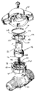
Figure 1 shows an exploded perspective view of the control members of a valve
according to the present invention; and
Figure 2 shows the valve in axial section and in the locked position.
The valve or faucet for fluids comprises a body 10, in which is provided in a
known
manner a duct 11 for the passage of fluid. In the body 10 is arranged a ball
stop valve 12
rotating between a closing position and an opening position of the duct 11.
Control means 13,
14 are connected to the ball stop valve 12, by means of which the stop valve
can be rotated

CA 02430815 2003-06-03
2
90° between said two opening and closing positions. A throttle or grip
lever 15 is fit flush to
the control means for this rotation.
In accordance with the present invention, the control means comprise a first
pin 13 joined
to the ball stop valve 12 and a second pin 14 arranged in continuation of the
first [pin] and fixed
at an angle to same. The throttle or grip lever 15 is screwed to the tip of
said second pin 14. In
addition, the latter is axially movable in relation to the first pin 13
between a raised locking
position, in which it is fixed at an angle to the valve body and thus cannot
be rotated, and a
lowered unlocking position in which the throttle or grip lever 15, the two
pins 13, 14 and the ball
stop valve 12 can be rotated. For this purpose, the second pin 14 has a hollow
cylindrical base
I6 designed for coupling with and for sliding on the free end of the first pin
13. This cylindrical
base 16 is guided on the outside in a circular seat 17 provided in the body 10
of the valve. In the
upper part of the said circular seat 17 is provided a step 18, in which is
arranged a washer that
surrounds the second pin 14, being partially superimposed on the base 16, and
whose internal
shape, in combination with that of the said second pin, makes possible the
locking and unlocking
of same depending on its axial position.
In particular, the washer 19 has two diametrically opposed, radial slits, in
which a
longitudinal wall 21 of the second pin 14, which extends from the cylindrical
base 16, is designed
to engage. This wall 21 has a step 22 on each of the two sides in such a way
as to have a order
lower part designed to engage in the slits 20 of the washer and a narrower
upper part capable of
rotating in the washer without interfering in the said slits. The latter are,
moreover, joined
together by means of two opposed circumferential arches 23 so as to make
possible a 90° rotation
of the control means.
The second pin 14 is usually kept in the raised position by a helical spring
24
accommodated in an axial seat 24' provided in the first pin 13 and acting on
the cylindrical base
16 of the second pin I4.
For its locking at an angle to the body 10 of the valve, the washer 19 has at
least one radial
tooth 25, which is inserted into a corresponding notch 25' provided in the
said body 10. Finally,
the washer 19 and the two pins 13, 14 are kept in the respective seats in the
body of the valve by
an elastic ring 26 arranged and locked above the washer 19.
As stated it appears evident that, before rotating the throttle or grip lever
15 starting
from the locked position, it is necessary to exert a pressure in the axial
direction on the said
throttle in such a way that the second pin 14 is moved towards the first
[pin], which is
disengaged from the slits of the washer 19. Only at this point is it possible
to rotate the
control members 90° in order to open or close the valve. Once brought
back to the starting
angular position, these control members shall automatically return into the
locking position
thanks to the upward force of the spring 24.

Dessin représentatif
Une figure unique qui représente un dessin illustrant l'invention.
États administratifs

2024-08-01 : Dans le cadre de la transition vers les Brevets de nouvelle génération (BNG), la base de données sur les brevets canadiens (BDBC) contient désormais un Historique d'événement plus détaillé, qui reproduit le Journal des événements de notre nouvelle solution interne.

Veuillez noter que les événements débutant par « Inactive : » se réfèrent à des événements qui ne sont plus utilisés dans notre nouvelle solution interne.

Pour une meilleure compréhension de l'état de la demande ou brevet qui figure sur cette page, la rubrique Mise en garde , et les descriptions de Brevet , Historique d'événement , Taxes périodiques et Historique des paiements devraient être consultées.

Historique d'événement

Description Date
Demande non rétablie avant l'échéance 2006-06-05
Le délai pour l'annulation est expiré 2006-06-05
Inactive : CIB de MCD 2006-03-12
Réputée abandonnée - omission de répondre à un avis sur les taxes pour le maintien en état 2005-06-03
Demande publiée (accessible au public) 2004-10-30
Inactive : Page couverture publiée 2004-10-29
Inactive : CIB en 1re position 2003-08-07
Lettre envoyée 2003-07-09
Inactive : Certificat de dépôt - Sans RE (Anglais) 2003-07-09
Demande reçue - nationale ordinaire 2003-07-07

Historique d'abandonnement

Date d'abandonnement Raison Date de rétablissement
2005-06-03

Historique des taxes

Type de taxes Anniversaire Échéance Date payée
Taxe pour le dépôt - générale 2003-06-03
Enregistrement d'un document 2003-06-03
Titulaires au dossier

Les titulaires actuels et antérieures au dossier sont affichés en ordre alphabétique.

Titulaires actuels au dossier
VALVOSANITARIA BUGATTI S.P.A.
Titulaires antérieures au dossier
ANGELO TRAPPA
Les propriétaires antérieurs qui ne figurent pas dans la liste des « Propriétaires au dossier » apparaîtront dans d'autres documents au dossier.
Documents

Pour visionner les fichiers sélectionnés, entrer le code reCAPTCHA :


Pour visualiser une image, cliquer sur un lien dans la colonne description du document (Temporairement non-disponible). Pour télécharger l'image (les images), cliquer l'une ou plusieurs cases à cocher dans la première colonne et ensuite cliquer sur le bouton "Télécharger sélection en format PDF (archive Zip)" ou le bouton "Télécharger sélection (en un fichier PDF fusionné)".

Liste des documents de brevet publiés et non publiés sur la BDBC .

Si vous avez des difficultés à accéder au contenu, veuillez communiquer avec le Centre de services à la clientèle au 1-866-997-1936, ou envoyer un courriel au Centre de service à la clientèle de l'OPIC.

({010=Tous les documents, 020=Au moment du dépôt, 030=Au moment de la mise à la disponibilité du public, 040=À la délivrance, 050=Examen, 060=Correspondance reçue, 070=Divers, 080=Correspondance envoyée, 090=Paiement})


Description du
Document 
Date
(aaaa-mm-jj) 
Nombre de pages   Taille de l'image (Ko) 
Abrégé 2003-06-02 1 14
Description 2003-06-02 2 147
Revendications 2003-06-02 1 79
Dessins 2003-06-02 2 62
Dessin représentatif 2003-09-21 1 14
Courtoisie - Certificat d'enregistrement (document(s) connexe(s)) 2003-07-08 1 105
Certificat de dépôt (anglais) 2003-07-08 1 158
Rappel de taxe de maintien due 2005-02-06 1 109
Courtoisie - Lettre d'abandon (taxe de maintien en état) 2005-07-31 1 175