Note : Les descriptions sont présentées dans la langue officielle dans laquelle elles ont été soumises.
CA 02433023 2003-06-20
WO 02/063224 PCT/US02/04025
APPARATUS AND METHOD FOR DISCHARGING FLUID
BACKGROUND OF THE INVENTION
[0001] The present invention relates generally to apparatus and methods for
discharging fluids. More particularly, the present invention relates to an
apparatus
and associated method for discharging, from an outlet chamber of a heat
exchanger, a
fluid and a liquid separated from the fluid.
[0002] Air-conditioning, refrigeration, or heat-pump systems typically include
a
compressor, two heat exchangers, and an expansion valve. These components are
connected by a series of tubes and pipes to form a circuit through which a
fluid flows
for cooling or heating a space or a heat transfer fluid. Typically the fluid
undergoes a
phase change while flowing through the heat exchangers. In one of the heat
exchangers conventionally called a condenser, at least a portion of the fluid
undergoes
a phase change from vapor to liquid, and thereby loses its heat content. In
the other
heat exchanger conventionally called an evaporator, at least a portion of the
fluid
undergoes a phase change from liquid to vapor, and thereby increases its heat
content.
Thus, in an air-conditioning or refrigeration system, a space or a heat
transfer fluid to
be cooled is coupled with the evaporator. In a heat-pump system, on the other
hand, a
space or a heat transfer fluid to be heated is coupled with the condenser.
Also, a
single system may serve as both an air-conditioning or refrigeration system
and a
heat-pump system by reversing the flow of the fluid.
[0003] The fluid in air-conditioning, refrigeration, or heat-pump systems
enters
the evaporator in the form of a subcooled liquid, a saturated liquid, or a
mixture of
liquid and vapor. While the fluid flows through the evaporator in small metal
tubes, it
absorbs heat from a space or a heat transfer fluid and at least part of the
liquid portion
becomes vapor. Thus, depending on the amount of heat absorbed by the fluid,
the
fluid exits the evaporator in the form of a mixture of liquid and vapor, a
saturated
vapor, or a superheated vapor. The fluid then flows through the compressor to
increase its pressure. Subsequently, the fluid flows through the condenser
where it
loses heat to another space or another heat transfer fluid. Depending on the
amount of
-1-
CA 02433023 2003-06-20
WO 02/063224 PCT/US02/04025
heat lost by the fluid, the fluid exits the condenser in the form of a
subcooled liquid, a
saturated liquid, or a mixture of liquid and vapor. While the fluid exiting
the
evaporator or the condenser may assume different forms, at least a portion of
the fluid
undergoes a phase change due to either heat loss or heat absorption.
[0004] Certain air-conditioning, refrigeration, or heat-pump systems are
designed
such that the fluid exiting the evaporator contains a mixture of liquid and
vapor. For
example, because the heat transfer characteristic of the fluid is typically
poor if more
than 90% of the fluid is vapor, an evaporator in a certain air-conditioning or
refrigeration system is designed to produce a fluid that contains about 90%
vapor
portion and 10% liquid portion at its outlet chamber. This evaporator may
achieve the
maximum heat removal from a space or other heat transfer fluid to be cooled.
Part of
the liquid portion in the fluid, however, fails to exit the evaporator
directly with a bulk
flow because it tends to separate from the bulk flow and collects at the
bottom portion
of the outlet chamber due to gravity. For example, as much as 75% of the
liquid
portion may separate from the bulk flow and fall to the bottom of the outlet
chamber.
This separated liquid collecting in the outlet chamber poses at least three
problems.
[0005] First, the separated liquid may eventually damage the compressor. As
the
separated liquid continues to build up in the outlet chamber, the liquid level
approaches an outlet opening. The liquid then tends to flow out suddenly in a
large
volume through the outlet opening. This phenomenon is commonly referred to as
a
liquid "slug." During ongoing operations, the liquid collected in the outlet
chamber
continues this pattern of build up and sudden "slug" removal rather than a
steady and
continuous removal. This pattern, referred to as a cyclical purging, may
eventually
decrease a compressor life. Although compressors may endure a steady and
continuous influx of liquid in small amount, they are typically not designed
to bear
cyclical influxes of large liquid "slugs."
[0006] Second, the separated liquid may hinder the flow of the fluid through
the
evaporator. As the liquid builds up, it blocks some of the metal tubes through
which
the fluid discharges to the outlet chamber. This blockage impedes a steady
flow of
-2-
CA 02433023 2003-06-20
WO 02/063224 PCT/US02/04025
the fluid and may decrease the efficiency of the overall air-conditioning,
refrigeration,
or heat-pump system.
[0007] Third, the separated liquid may deprive needed liquids to other
components of the air-conditioning, refrigeration, or heat-pump system. For
example,
in some applications, the fluid includes a small amount of oil to ensure
smooth
mechanical operation of the compressor. This oil typically falls with the
separated
liquid to the bottom of the outlet chamber. Without a continuous, steady
removal of
the separated liquid from the outlet chamber, the oil needed for a proper
mechanical
operation may not reach the compressor.
[0008] Therefore, there exists a need for an apparatus and method for
continuously and steadily discharging a liquid, which is separated from the
bulk flow
of a fluid and collected in an outlet chamber.
SUN>NIARY OF THE INVENTION
[0009] Accordingly, the present invention is directed to an apparatus and
associated method for discharging, from an outlet chamber of a heat exchanger,
a
fluid and a liquid separated from the fluid that obviate one or more of the
limitations
and disadvantages of prior art apparatus and methods. The advantages and
purposes
of the invention will be set forth in part in the description which follows,
and in part
will be obvious from the description, or may be learned by practice of the
invention.
The advantages and purposes of the invention will be realized and attained by
the
elements and combinations particularly pointed out in the appended claims.
[0010] To attain the advantages and in accordance with the purposes of the
invention, as embodied and broadly described herein, the invention is directed
to an
apparatus for discharging from an outlet chamber a fluid and a liquid
separated from
the fluid. The outlet chamber is configured to collect the separated liquid.
The outlet
chamber is in fluid communication with an outlet opening disposed on an exit
surface
of the outlet chamber. The apparatus includes a plate positionable in the
outlet
chamber adjacent to the exit surface to form a channel between the plate and
the exit
surface. The plate is configured to protrude over the outlet opening so that
the fluid
-3-
CA 02433023 2003-06-20
WO 02/063224 PCT/US02/04025
flowing through the outlet chamber and into the outlet opening pulls the
liquid
collected in the outlet chamber through the channel and out through the outlet
opening
with the fluid.
[0011] In another aspect, the invention is directed to a method for
discharging
from an outlet chamber a fluid and a liquid separated from the fluid. The
outlet
chamber is configured to collect the separated liquid. The outlet chamber is
in fluid
communication with an outlet opening disposed on an exit surface of the outlet
chamber. The method steps includes: positioning a plate in the outlet chamber
adjacent to the exit surface so that the plate and the exit surface form a
channel
therebetween and the plate protrudes over the outlet opening; and flowing the
fluid
through the outlet chamber and into the outlet opening to pull the liquid
collected in
the outlet chamber through the channel and out through the outlet opening with
the
fluid.
[0012] In yet another aspect, the invention is directed to a heat exchanger.
The
heat exchanger includes a main chamber, an outlet chamber, an outlet opening,
and a
plate. A fluid flows through the main chamber to absorb heat. The outlet
chamber is
configured to receive the fluid from the main chamber and to collect a liquid
separated from the fluid. The outlet opening is disposed on an exit surface of
the
outlet chamber and is in fluid communication with the outlet chamber. The
plate is
positioned in the outlet chamber adjacent to the exit surface to form a
channel
between the plate and the exit surface. The plate protrudes over the outlet
opening so
that the fluid flowing through the outlet chamber and into the outlet opening
pulls the
liquid collected in the outlet chamber through the channel and out through the
outlet
opening with the fluid.
[0013] In yet another aspect, the invention is directed to a heat exchanging
system
having a fluid flowing therethrough in a cycle. The heat exchanging system
includes
a compressor, a first heat exchanger, an expansion device, and a second heat
exchanger. The first heat exchanger receives the fluid from the compressor and
discharges the fluid after the fluid loses heat while flowing through the
first heat
exchanger. The expansion device receives the fluid from the first heat
exchanger.
-4-
CA 02433023 2003-06-20
WO 02/063224 PCT/US02/04025
The second heat exchanger receives the fluid from the expansion device and
discharges the fluid to the compressor. The second heat exchanger includes a
main
chamber, an outlet chamber, an outlet opening, and a plate. The fluid flows
through
the main chamber to absorb heat. The outlet chamber is configured to receive
the
fluid from the main chamber and to collect a liquid separated from the fluid.
The
outlet opening is disposed on an exit surface of the outlet chamber and is in
fluid
communication with the outlet chamber. The plate is positioned in the outlet
chamber
adjacent to the exit surface to form a channel between the plate and the exit
surface.
The plate protrudes over the outlet opening so that the fluid flowing through
the outlet
chamber and into the outlet opening pulls the liquid collected in the outlet
chamber
through the channel and out through the outlet opening with the fluid.
[0014] It is to be understood that both the foregoing general description and
the
following detailed description are exemplary and explanatory only and are not
restrictive of the invention, as claimed.
BRIEF DESCRIPTION OF THE DRAWINGS
[0015] The accompanying drawings are included to provide a further
understanding of the invention and are incorporated in and constitute a part
of this
specification. The drawings illustrate embodiments of the invention and,
together
with the description, serve to explain the principles of the invention.
[0016] Fig. 1 is a schematic diagram of an air-conditioning, refrigeration, or
heat-
pump system in accordance with the present invention.
[0017] Fig. 2 is a side view of a direct expansion evaporator in accordance
with
the present invention.
[0018] Fig. 3 is a front view of a plate in accordance with the present
invention.
[0019] Fig. 4 is a front view of a plate and an outlet chamber of a direct
expansion
evaporator in accordance with the present invention.
-5-
CA 02433023 2003-06-20
WO 02/063224 PCT/US02/04025
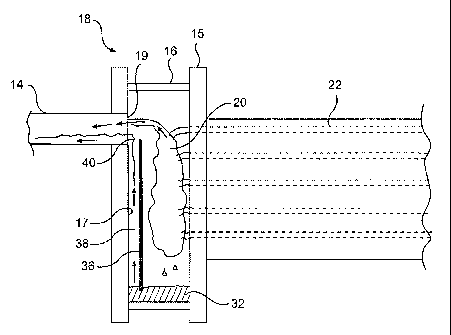
[0020] Fig. 5 is a side, sectional view of a direct expansion evaporator in
accordance with the present invention illustrating a bulk fluid flow and a
liquid
collected at the bottom portion of an outlet chamber after separating from the
bulk
fluid flow.
[0021] Fig. 6 is a side, sectional view of a direct expansion evaporator in
accordance with the present invention illustrating a liquid collected at the
bottom
portion of an outlet chamber exiting a direct expansion evaporator with a bulk
fluid
flow.
[0022] Fig. 7 is a perspective view of an outlet chamber of a direct expansion
evaporator and a plate having horizontal walls in accordance with the present
invention.
[0023] Fig. 8 is a perspective view of an outlet chamber of a direct expansion
evaporator and a plate having diagonal walls in accordance with the present
invention.
DETAILED DESCRIPTION OF THE INVENTION
[0024] Reference will now be made in detail to the presently preferred
embodiment of the present invention, an example of which is illustrated in the
accompanying drawings. Wherever possible, the same reference numbers will be
used throughout the drawings to refer to the same or like parts.
[0025] In accordance with the present invention and illustrated in Fig. 1, an
air-
conditioning, refrigeration, or heat-pump system includes two heat exchangers
11 and
15, a compressor 13, and an expansion valve 25. Tubes or pipes connect heat
exchangers 11 and 15, compressor 13, and expansion valve 25. A fluid at a
given
pressure flows through heat exchanger 15, conventionally called a condenser.
While
flowing through condenser 15, the fluid loses heat. The fluid then flows
through
expansion valve 25 where its pressure decreases to another level. The fluid
then
flows through heat exchanger 11, conventionally called an evaporator. While
flowing
though evaporator 11, the fluid absorbs heat. Finally, the fluid flows through
compressor 13 where its pressure increases back to the original level. Thus,
the fluid
-6-
CA 02433023 2003-06-20
WO 02/063224 PCT/US02/04025
flowing through the system form an air-conditioning, refrigeration, or heat-
pump
cycle. Heat exchangers 11 and 15 are respectively called an evaporator and a
condenser because at least a portion of the fluid undergoes a phase change
while
flowing though them. At least a portion of the fluid changes from liquid to
vapor in
evaporator 11 while at least a portion of the fluid changes from vapor to
liquid in
condenser 15.
[0026] Because the fluid flowing through evaporator 11 absorbs heat, an air-
conditioning or refrigeration system results if evaporator 11 is placed in a
space to be
cooled. On the other hand, because the fluid flowing through condenser 1 5
loses
heat, a heat-pump system results if condenser 15 is placed in a space to be
heated.
Evaporator 11 and condenser 15 may directly cool or heat a space (e.g.,
through air
inside). Alternatively, evaporator 11 and condenser 15 may exchange heat with
other
heat transfer fluids (e.g., water) which in turn will either cool or heat a
space through
another heat transfer mechanism.
[0027] Furthermore, a system that exchanges heat directly with outside air can
serve as both an air-conditioning or refrigeration system and a heat-pump
system. For
example, during the summer, the system shown in Fig. 1 may serve as an air-
conditioning or refrigeration system where evaporator 11 cools inside air by
absorbing heat while condenser 15 loses heat to outside air. In this air-
conditioning or
refrigeration system, the fluid flows in a direction indicated by reference
number 21.
During the winter, on the other hand, expansion valve 25 may actuate to
reverse the
flow of the fluid in the other direction indicated by reference number 23 to
transform
the air-conditioning or refrigeration system into a heat-pump system. In this
heat-
pump system, heat exchanger l l becomes a condenser, which warms the inside
air by
losing heat, while heat exchanger I S becomes an evaporator, which absorbs
heat from
the outside air.
(0028] For purposes of illustrating the preferred embodiment of the present
invention, the detailed descriptions below are directed to an exemplary
refrigeration
system having a direct expansion evaporator absorbing heat from a heat
transfer fluid.
However, the present invention is by no means limited to a particular system
or heat
_7_
CA 02433023 2003-06-20
WO 02/063224 PCT/US02/04025
exchanger. Rather, the present invention encompasses any device and method for
discharging a liquid separated from a bulk flow continuously and steadily with
the
bulk flow.
[0029] Fig. 2 shows a direct expansion evaporator 11 in a refrigeration
system.
Direct expansion evaporator 11 includes a refrigerant inlet 10, a main chamber
12,
and a refrigerant outlet 14. Direct expansion evaporator 11 also includes an
outlet
chamber 16 located at its last pass 18. A refrigerant enters direct expansion
evaporator 11, flows through evaporator tubes 22, arranged in a bundle within
main
chamber 12, and flows into outlet chamber 16 before exiting through
refrigerant outlet
14. At the same time, a heat transfer fluid (e.g., water) enters main chamber
12
through a heat transfer fluid inlet 26, flows across the outside surfaces of
evaporator
tubes 22, and then exits the main chamber 12 through a heat transfer fluid
outlet 28.
While the refrigerant and the heat transfer fluid flow through direct
expansion
evaporator 11, the refrigerant absorbs heat from the heat transfer fluid.
Consequently,
the heat transfer fluid loses its heat content (e.g., the temperature of the
heat transfer
fluid decreases). The heat transfer fluid may then cool a space or other
things through
another heat transfer mechanism.
[0030] As a result of absorbing heat from the heat transfer fluid, at least a
portion
of the refrigerant undergoes a phase change from liquid to vapor. Thus, the
refrigerant entering outlet chamber 16 typically becomes a mixture of liquid
and
vapor. However, depending on the particular design of direct expansion
evaporator
11 and the heat content of the heat transfer fluid, all the refrigerant
entering outlet
chamber 16 may become vapor. In other words, all the refrigerant entering
outlet
chamber 16 may become saturated vapor or superheated vapor. Furthermore, the
refrigerant may contain oil (e.g., lubrication oil) to ensure smooth
mechanical
operation of compressor 13 (Fig. 1). Unlike the refrigerant, the oil in a
liquid form
does not undergo a phase change. Accordingly, the fluid entering outlet
chamber 16
may contain (1) a mixture of refrigerant vapor and liquid without oil, (2)
refrigerant
vapor without oil, (3) a mixture of refrigerant vapor and liquid with oil, or
(4)
refrigerant vapor with oil.
_g_
CA 02433023 2003-06-20
WO 02/063224 PCT/US02/04025
[0031] As illustrated in Fig. 5, the bulk of the fluid entering outlet chamber
16
directly exits outlet chamber 16 through an outlet opening 19. Reference
number 20
designates this bulk flow of the fluid. However, part of the liquid portion in
the fluid
tends to separate from bulk flow 20 and falls to the bottom of outlet chamber
16 due
to gravity. The separated liquid collected at the bottom portion of outlet
chamber 16
may be liquid refrigerant 30, oil 34, or a mixture thereof. Even if the
refrigerant
entering outlet chamber 16 is all vapor, liquid refrigerant may form due to
the vapor
losing heat in outlet chamber 16. This newly-formed liquid refrigerant may
separate
from bulk flow 20 and fall to the bottom portion of outlet chamber 16 as well.
[0032] To continuously and steadily discharge the collected liquid with bulk
flow
20, outlet chamber 16 includes a plate 36. Plate 36 cooperates with adjacent
surfaces
of outlet chamber 16 and the flow characteristics within outlet chamber 16 to
continuously and steadily discharge the collected liquid with bulk flow 20. As
illustrated in Fig. 5, plate 36 is positioned within outlet chamber 16
adjacent to an exit
surface 17 of outlet chamber 16. Exit surface 17 and plate 36 are separated by
distance d and form a channel 38 therebetween. The bottom of plate 36 is
spaced
from the bottom of outlet chamber 16 by distance h so that the collected
liquid 32 can
enter channel 38 through a flow path 39. Plate 36 protrudes over outlet
opening 19 by
distance s to create a low pressure region to draw up collected liquid 32
though
channel 38.
[0033] As illustrated in Fig. 6, plate 36 protrudes over outlet opening 19 by
distance s (Fig. 5) so that bulk flow 20 flowing into outlet opening 19 must
pass
through a reduced area. Because of the reduced area, the versa contracta
effect
increases the velocity of bulk flow 20 and, at the same time, decreases the
pressure of
bulk flow 20 in a region 40. Thus, plate 36 protruding over outlet opening 19
and
bulk flow 20 create a lower-pressure region 40. In addition to the versa
contracta
effect, bulk flow 20 induces a pressure drop due to friction loss. This
pressure drop
due to friction loss also contributes to the creation of low pressure region
40.
[0034] This low pressure region 40 draws up collected liquid 32 though channel
38 between plate 36 and exit surface 17 when the level of collected liquid 32
rises
-9-
CA 02433023 2003-06-20
WO 02/063224 PCT/US02/04025
above h (Fig. 5). Then, as shown in Fig. 6, collected liquid 32 exits direct
expansion
evaporator 11 with bulk flow 20 through outlet opening 19. Low pressure region
40
may flash a portion of liquid refrigerant 30 (Fig. S) into vapor as collected
liquid 32 is
drawn up through channel 38. No oil 34, however, becomes vapor as collected
liquid
32 is drawn up through channel 38. The flashing of liquid refrigerant 30 is
believed
to be minimal, if any, because the pressure differential between low pressure
region
40 and collected liquid 32 is small.
(0035] Preferably, the distances d, h, and s shown in Fig. 5 are determined
through empirical testing. The distances d, h, and s vary depending on many
factors,
including, among other things, the operating conditions of the evaporator, the
size of
outlet opening 19, the size of outlet chamber 16, the desired flow
characteristics of
collected liquid 32 through channel 38, the capacity of the refrigeration
system, the
operating pressure of direct expansion evaporator 11. The distances d, h and s
may be
determined, or at least approximated, analytically given the desired flow
characteristics of collected liquid 32 through channel 38, relevant dimensions
of direct
expansion evaporator 11, and flow characteristics of bulk flow 20. However, a
precise analytical determination may be extremely difficult because not all
flow
characteristics are readily known. Given these circumstances, empirical
determinations, with or without some initial approximation through analytical
determination, are preferred to determine the distances d, h, and s.
[0036] The following dimensions and placements are provided to further
illustrate
one preferred embodiment in accordance with the present invention. These
dimensions and placements correspond to an application in which 1 SO tons of
refrigeration are desired. However, it should be recognized that these
dimensions and
placements are exemplary in nature and do not limit the scope of the present
invention.
[0037) In an application in which 150 tons of refrigeration are desired, plate
36 is
preferably fabricated from a 1/8" thick circular piece of carbon steel (e.g.,
ASTM A-
36) having a diameter of 20". As shown in Figs. 3 and 4, the top and bottom
portions
of plate 36 are removed. Outlet chamber 16 is cylindrical in shape and
preferably has
- 10-
CA 02433023 2003-06-20
WO 02/063224 PCT/US02/04025
a 20" inside diameter, a length of 1 3/8" and a wall thickness of'/z". The
diameters of
plate 36 and outlet chamber 16 are the same so that plate 36 stretches all the
way to
the sides of outlet chamber 16 as shown in Fig. 4. Plate 36 is joined with the
side
surfaces of outlet chamber 16 by welding, press-fitting, or other known
techniques to
provide channel 38 between plate 36 and exit surface 17 from the bottom of
plate 36
to the top thereof. Channel 38 does not have to provide a fluid-tight seal for
the
purpose of the present invention.
[0038] Refrigerant outlet 14 has an outside diameter of 2'/2" and a thickness
of
1/16". It is located 2'/Z" from the top of outlet chamber 16, measured from
the inside
of the top of outlet chamber 16 to the inside of the top of refrigerant outlet
14. Plate
36 is placed '/4" (the distance din Fig. S) from exit surface 17 and protrudes
'/z" (the
distance s in Fig. 5) above the inside of the bottom of refrigerant outlet 14.
The
bottom of plate 36 is placed '/4" to '/z" (the distance h in Fig. 5) from the
bottom of
outlet chamber 16. The tube head 27 is 3/4" thick and has S/8" holes to
support
multiple 5/8" evaporator tubes 22.
[0039] Again, all of these dimensions and placements are used in an
application in
which 150 tons of refrigeration are desired. The present invention, however,
encompasses more than just the preferred embodiment described above. Any
variations that produce a steady and continuous removal of a liquid separated
from a
bulk fluid flow is encompassed by the present invention regardless of the
desired total
refrigerant output.
[0040) Although Figs. 3 and 4 show the top and bottom of plate 36 as straight,
they may assume different forms. For example, the top and bottom of plate 36
may
be curved rather than straight. Also, a pair of horizontal wails 42, separated
by a
predetermined distance, may be provided at the top of plate 36 around outlet
opening
19 as shown in Fig. 7. These horizontal walls 42 extend from the top of plate
36 to
exit surface 17 where they are joined with exit surface 17 by welding, press-
fitting, or
other known techniques. These horizontal walls 42 improve the flow efficiency
of the
collected liquid by preventing it from taking a tortuous path before entering
outlet
opening 19. For example, without horizontal walls 42, the collected liquid may
flow
-11-
CA 02433023 2003-06-20
WO 02/063224 PCT/US02/04025
to the top of exit surface 17 and around outlet opening 19 many times before
finally
entering outlet opening 19. Horizontal walls 42 eliminate this flow
inefficiency
[0041] Alternatively, a pair of diagonal walls 44 may be provided within plate
36
as shown in Fig. 8. These diagonal walls 44 extend from the bottom of plate 36
to the
top thereof. These diagonal walls 44 also extend from a surface of plate 36
toward
exit surface 17 where they are joined with exit surface 17 by welding, press-
fitting, or
other known techniques. Thus, instead of the side surfaces of outlet chamber
16,
these diagonal walls 44 form channel 38 in conjunction with plate 36 and exit
surface
17. These diagonal walls 44 also improve the flow efficiency of the collected
liquid
by guiding it directly to outlet opening 19. Thus, diagonal walls 44 prevent
the
collected liquid from taking a tortuous path before entering outlet opening
19. Of
course, plate 36 may be provided with horizontal walls 42 as well as diagonal
walls
44.
[0042] The operation of the aforementioned plate and direct expansion
evaporator
will now be described with reference to the attached drawings. It should be
recognized, however, that the present invention encompasses more than a direct
expansion evaporator in a refrigeration system. Although a direct expansion
evaporator in a refrigeration system is described in order to illustrate the
principles of
the present invention, the present invention encompasses any device and method
for
discharging a liquid separated from a bulk flow continuously and steadily with
the
bulk flow.
[0043] As shown in Fig. 2, a refrigerant flows through evaporator tubes 22 and
absorbs heat from a heat transfer fluid. The absorbed heat converts at least a
portion
of. the refrigerant from liquid to vapor. As a result, the refrigerant
entering outlet
chamber 16 becomes either a mixture of liquid and vapor or all vapor. Unlike
the
refrigerant, oil, which may be added to the refrigerant for lubrication,
remains in a
liquid form. Thus, the outlet chamber 16 may receive (1) a mixture of
refrigerant
liquid and vapor without oil, (2) refrigerant vapor without oil, (3) a mixture
of
refrigerant liquid and vapor with oil, or (4) refrigerant vapor with oil.
- 12-
CA 02433023 2003-06-20
WO 02/063224 PCT/US02/04025
[0044] As shown in Fig. S, the bulk of the fluid enters outlet chamber 16 and
directly exits through outlet opening 19. Part of the liquid portion, however,
separates
from bulk flow 20 and falls to the bottom portion of outlet chamber 16. This
liquid
portion, which separates from bulk flow 20 and collects at the bottom portion
of outlet
chamber 16, may be liquid refrigerant 30, oil 34, or a mixture thereof. Even
if the
refrigerant entering outlet chamber 16 is all vapor without oil, part of the
vapor may
become liquid by losing heat (e.g., heat loss to outside environment) in
outlet chamber
16. Part of this liquid may separate from bulk flow 20 and collect at the
bottom
portion of outlet chamber 16.
[0045] As shown in Fig. 6, collected liquid 32 is discharged continuously and
steadily through outlet opening 19 with bulk flow 20 when its level rises
above the
bottom of plate 36. Because plate 36 protrudes over outlet opening 19, bulk
flow 20
must pass through a decreased area before exiting through outlet opening 19.
This
decreased area produces the versa contracta effect, which leads to low
pressure region
40. Low pressure region 40 draws up collected liquid 32 through channel 38 and
discharges it through outlet opening 19 with bulk flow 20. Therefore, plate 36
removes collected liquid 32 continuously and steadily from outlet chamber 16,
and
thus avoids a sudden "slug" removal.
[0046] The present invention includes apparatus and related methods for
discharging a fluid and a liquid separated from the fluid and collected at the
bottom
portion of an outlet chamber. A bulk of the fluid directly exits the outlet
chamber
through an outlet opening disposed on an exit surface of the outlet chamber.
Part of
the liquid portion of the fluid, however, falls to and collects at the bottom
portion of
the outlet chamber due to gravity and fails to exit directly. To discharge the
collected
liquid from the outlet chamber with the bulk flow-of the fluid, a plate is
positioned
adjacent to the exit surface to form a channel therebetween. The plate
protrudes over
the outlet opening so that the bulk fluid flowing into the outlet opening must
pass
through a decreased area and thereby creates a low pressure region at the top
of the
channel. This low pressure region draws up the collected liquid through the
channel
and discharge it through the outlet opening with the bulk flow. Consequently,
the
collected liquid is discharged continuously and steadily without a sudden
"slug"
-13-
CA 02433023 2003-06-20
WO 02/063224 PCT/US02/04025
discharge. Preferably, the present invention is used in a direct expansion
evaporator
of a refrigeration system. The present invention, however, may be used in any
device
to discharge a liquid separated from a bulk fluid continuously and steadily
with the
bulk fluid.
[0047] It will be apparent to those skilled in the art that various
modifications
and variations can be made to the structure and method of the present
invention
without departing from the scope or spirit of the invention. Other embodiments
of the
invention will be apparent to those skilled in the art from consideration of
the
specification and practice of the invention disclosed herein. It is intended
that the
specification and examples be considered as exemplary only, with a true scope
and
spirit of the invention being indicated by the following claims.
- 14-