Sélection de la langue

Search

Sommaire du brevet 2434179 

Énoncé de désistement de responsabilité concernant l'information provenant de tiers

Une partie des informations de ce site Web a été fournie par des sources externes. Le gouvernement du Canada n'assume aucune responsabilité concernant la précision, l'actualité ou la fiabilité des informations fournies par les sources externes. Les utilisateurs qui désirent employer cette information devraient consulter directement la source des informations. Le contenu fourni par les sources externes n'est pas assujetti aux exigences sur les langues officielles, la protection des renseignements personnels et l'accessibilité.

Disponibilité de l'Abrégé et des Revendications

L'apparition de différences dans le texte et l'image des Revendications et de l'Abrégé dépend du moment auquel le document est publié. Les textes des Revendications et de l'Abrégé sont affichés :

  • lorsque la demande peut être examinée par le public;
  • lorsque le brevet est émis (délivrance).
(12) Demande de brevet: (11) CA 2434179
(54) Titre français: JOINT METALLIQUE PLAT ET PROCEDE DE FABRICATION
(54) Titre anglais: METALLIC FLAT GASKET AND METHOD FOR ITS PRODUCTION
Statut: Réputée abandonnée et au-delà du délai pour le rétablissement - en attente de la réponse à l’avis de communication rejetée
Données bibliographiques
(51) Classification internationale des brevets (CIB):
  • F16J 15/06 (2006.01)
  • F02F 11/00 (2006.01)
  • F16J 15/08 (2006.01)
(72) Inventeurs :
  • WAMPULA, TORSTEN (Allemagne)
  • LUDWIG, JOSEF (Allemagne)
  • WEISS, ALFRED (Allemagne)
  • UNSELD, GUENTHER (Allemagne)
  • LASKE, MATTHIAS (Allemagne)
  • DILLENZ, FRIEDRICH (Allemagne)
(73) Titulaires :
  • REINZ-DICHTUNGS-GMBH
(71) Demandeurs :
  • REINZ-DICHTUNGS-GMBH (Allemagne)
(74) Agent: OSLER, HOSKIN & HARCOURT LLP
(74) Co-agent:
(45) Délivré:
(86) Date de dépôt PCT: 2002-01-17
(87) Mise à la disponibilité du public: 2002-07-25
Requête d'examen: 2006-02-10
Licence disponible: S.O.
Cédé au domaine public: S.O.
(25) Langue des documents déposés: Anglais

Traité de coopération en matière de brevets (PCT): Oui
(86) Numéro de la demande PCT: PCT/EP2002/000427
(87) Numéro de publication internationale PCT: WO 2002057667
(85) Entrée nationale: 2003-07-07

(30) Données de priorité de la demande:
Numéro de la demande Pays / territoire Date
101 02 288.3 (Allemagne) 2001-01-19

Abrégés

Abrégé français

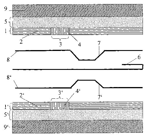
L'invention concerne un joint plat métallique comprenant au moins une couche d'étanchéité (8, 8') pourvue d'au moins une ouverture de passage. Selon l'invention, sur au moins une surface de la couche d'étanchéité est appliquée une couche capteur (1, 1') qui lui correspond en ce qui concerne les ouvertures de passage et qui est constituée d'une couche (2, 2') protégeant contre la compression et d'au moins un évidement dans lequel un élément capteur (12) est au moins partiellement intégré.


Abrégé anglais


The invention relates to a flat metallic seal comprising at least one sealing
layer (8, 8') in which at least one continuous opening is made. A sensor layer
(1, 1') is arranged on at least one surface of the sealing layer corresponding
to the continuous openings. Said sensor layer is made of an anti- compression
protective layer (2, 2') and at least one recess, into which a sensor element
(12) is at least partially incorporated.

Revendications

Note : Les revendications sont présentées dans la langue officielle dans laquelle elles ont été soumises.


Claims
1. Metallic flat gasket with at least one sealing layer with at least one
port, for which a
sensor layer (1,1') corresponding to the ports is deposited on at least one
surface of the sealing
layer, with the sensor layer consisting of a compression protection layer
(2,2') and at least one
break (3,3'), in which a sensor element (4,4') is at least partially
installed, and the sensor layer
(1,1') is arranged on the side of the cylinder head gasket facing the cylinder
head (9) and/or the
engine block (10).
2. Flat gasket according to Claim 1, characterized in that the sensor layer
(1,1') is
deposited on a separate carrier layer (5,5').
3. Flat gasket according to at least one of Claims 1 or 2, characterized in
that structures
are stamped in the carrier layer (5,5') on the side facing the sensor element
(4,4'), with the sensor
element and/or connection elements extending into these structures.
4. Flat gasket according to at least one of Claims 1-3, characterized in that
a
heat-conductive layer is deposited on the side of the sensor element (4,4')
facing away from the
carrier layer (5,5').
5. Flat gasket according to at least one of Claims 1-4, characterized in that
a layer that
protects against mechanical damage is deposited on the side of the sensor
element (4,4') facing
away from the carrier layer (5,5').
6. Flat gasket according to at least one of Claims 1-5, characterized in that
the carrier
layer (5,5') consists of steel, aluminum, and/or other aluminum-containing
materials, such as
ceramics or enamels.
7. Flat gasket according to at least one of Claims 1-6, characterized in that
the carrier
layer (5,5') has a layer thickness .ltoreq.300 µm, preferably ca. 150
µm.
8. Flat gasket according to at least one of Claims 1-7, characterized in that
the
compression protection layer (2,2') has a layer thickness .ltoreq.300 µm,
preferably ca. 200 µm.
9. Flat gasket according to at least one of Claims 1-8, characterized in that
the
compression protection layer (2,2') consists of steel, aluminum, and/or other
aluminum-containing materials, such as ceramics or enamels.
10. Flat gasket according to at least one of Claims 1-9, characterized in that
the
compression protection layer (2,2') is electrically insulated at the end sides
of the recess.
11. Flat gasket according to at least one of Claims 1-10, characterized in
that the
compression protection layer (2,2') also has a bead and/or a stopper.
12. Flat gasket according to Claim 11, characterized in that the sensor
element (4,4') is
arranged next to the bead.

2
13. Flat gasket according to at least one of Claims 1-12, characterized in
that the sensor
element (4,4') is selected from the group of piezoelectric, piezoresistive,
capacitive, magnetic,
electromagnetic, DMS [wire strain gauge], eddy current, optical fiber, and
micromechanical
sensors.
14. Flat gasket according to at least one of Claims 1-13, characterized in
that the sensor
element (4,4') is a thick-film sensor.
15. Flat gasket according to at least one of Claims 1-13, characterized in
that the sensor
element (4,4') is a thin-film sensor.
16. Flat gasket according to at least one of Claims 1-15, characterized in
that the sensor
element (4,4') is a temperature sensor.
17. Flat gasket according to Claim 16, characterized in that the sensor
element is a
resistance sensor.
18. Flat gasket according to Claim 17, characterized in that the sensor
element is a PTC
temperature probe.
19. Method for producing a single-layer or multi-layer cylinder head gasket
with a sensor
element, characterized in that a compression protection layer (2,2') is
deposited on the metal
gasket in the direction towards the cylinder head (9) and/or the engine block
(10), with the
compression protection layer having at least one break (3,3'), in whose region
the sensor element
(4,4') is attached by a frictional connection.
20. Method according to Claim 19, characterized in that the frictional
connection is
realized through a thick-film deposition technique, such as, e.g., screen
printing.
21. Method according to Claim 20, characterized in that the frictional
connection is
realized through a thin-film deposition technique.
22. Method according to Claim 21, characterized in that the frictional
connection is
realized through a PVD technique.
23. Method according to Claim 19, characterized in that the frictional
connection is
realized through adhesive bonds, soldering, and/or locking devices.
24. Method according to at least one of Claims 19-23, characterized in that a
compression
protection layer (2,2') made from steel, aluminum, and/or other aluminum-
containing materials,
such as ceramics or enamels, is used.
25. Method according to at least one of Claims 19-24, characterized in that
the carrier
layer (5,5') made from steel, aluminum, and/or other aluminum-containing
materials, such as
ceramics or enamels, is deposited.
26. Use of the flat gasket according to at least one of Claims 1-18 for
temperature
measurements at combustion chamber openings.

3
27. Use of the flat gasket according to at least one of Claims 1-18 for force,
path,
expansion, acceleration, and/or pressure measurements at combustion chamber
openings.

Description

Note : Les descriptions sont présentées dans la langue officielle dans laquelle elles ont été soumises.


CA 02434179 2003-07-07
METALLIC FLAT GASKET AND METHOD FOR ITS PRODUCTION
The invention concerns a metallic flat gasket with at least one sealing layer
with at least
one port for sealing ofl' two components from each other. Here, a sensor
element is integrated in
the system, such that it is protected from compression.
Metallic sealing systems are used in the automotive industry primarily as
cylinder head
gaskets. Here, cylinder head gaskets are used to seal off various chambers,
such as combustion
chambers, coolant and lubricant openings, threaded bolts, as wells as ports
for valve control
parts, from each other. The requirements on these sealing systems continue to
become
increasingly rigorous and the recording of measurement data for characteristic
parameters of the
gasket appears to be desirable. Here, the measurement in the direct vicinity
of the corresponding
openings enables data recording that is as precise as possible. Due to these
requirements on the
dimensioning, sensor measurements are coming more and more to the forefront.
The teaching of DE I 99 13 092 concerns a cylinder head gasket, on which a
sensor
device for detecting measurement values is arranged.
However, the disadvantage of the prior art is that the danger of compression
of the sensor
element is so great that only very robust sensors can be used.
Thus, the problem of the present invention is to devise a metallic sealing
system that
contains a sensor element that is protected from compression.
This problem is solved by the generic metallic flat gasket with the features
of Claim 1
and by the generic production method with the features of Claim 20. The
additional subordinate
claims present advantageous refinements. In the Claims 27 and 28, the use of
the sealing system
is described.
According to the invention, a metallic flat gasket with at least one sealing
layer with at
least one port is created, with a corresponding sensor layer relative to the
ports deposited on at
least one surface of the sealing layer, which consists of a compression
protection layer with at
least one break. Here, the compression protection layer is used to protect the
sensor element from
mechanical damage and consists of an incompressible material, e.g., high-
hardness steel. Here,
the sensor element is at least partially installed in the break of the
compression protection layer.
In a preferred configuration, the sensor layer is deposited on a separate
carrier layer.
Thus, the deposition of the sensor layer can be performed independently of the
production
process of the cylinder head gasket. Simultaneously, the carrier layer can be
selected in regard to
an optimum adhesive bond between the sensor layer and sealing layer.
Here, the sensor layer can be arranged on one side of the cylinder head gasket
facing
either the cylinder head or the engine block. Likewise, it is possible for one
sensor layer to be
deposited on both sides. This allows the arrangement of several sensor
elements on both sides of

CA 02434179 2003-07-07
2
the metallic sealing system. Likewise, the carrier layer can be arranged on
one side of the
metallic sealing system facing either the cylinder head or the engine block.
In an advantageous refinement, the sensor element is at least partially
installed in the
Garner layer. Here, e.g., there can also be a break, in which the sensor
element can be inserted.
Likewise, the carrier layer can also have additional corresponding structures
for connection
elements to a measurement value detector unit, in addition to the structures
for the sensor
element. These structures can include lines or contacts. In a similar way, the
compression
protection layer can also have structures for the connection elements. The
advantage of such
structures is that, in addition to the sensor element itself, the connection
elements can also be
protected from compression.
In a preferred configuration, a thermally conductive layer is deposited on the
end side of
the sensor element facing away from the carrier layer. The thermal
conductivity of this layer
should be su~ciently high that a nearly error-free temperature measurement can
be performed
across this thermally conductive layer at the corresponding component. For
example, a thermally
conductive paste can be used as the thermally conductive layer. It is also
preferable if the carrier
layer, which faces the engine block and/or the cylinder head, has a high
thermal conductivity
value.
In a preferred configuration, a layer that protects against mechanical damage
is deposited
on the side of the sensor element facing away from the carrier layer. This
protection layer
provides improved protection against compression, and even more protection
against wear and
tear due to friction.
In an advantageous refinement, the carrier layer is produced from steel,
aluminum, and/or
other aluminum-containing materials, such as ceramics or enamels. Here, the
carrier layer
preferably has a layer thickness of less than 300 Vim, with a layer thickness
of approximately
150 pm being especially preferred.
The compression protection layer, which preferably consists of high-hardness
steel,
aluminum, and/or other aluminum-containing materials, such as ceramics or
enamels, preferably
has a layer thickness of less than 300 pm, with a layer thickness of
approximately 200 pm being
especially preferred. It is also preferred if the compression protection layer
is electrically
insulated at the end sides of the recess.
In a preferred refinement, the compression protection layer can also have a
bead and/or
stopper. Here, it is especially preferred if the sensor element is arranged in
the direct vicinity of
the bead in order to provide additional protection against compression.
Likewise, it is possible
for the sensor element itself to be stamped as a bead andlor stopper.
Preferably, the sensor element is selected from the group of piezoelectric,
piezoresistive,
capacitive, magnetic, electromagnetic, DMS [wire strain gauge], eddy current,
optical fiber, and

CA 02434179 2003-07-07
3
micromechanical sensors. The sensor element is preferably designed as a
temperature sensor.
The use of a resistor sensor as the sensor element in the flat gasket is
likewise preferred.
Especially preferred is the use of a PTC temperature probe as the sensor
element.
According to the invention, a method for producing a single-layer or multi-
layer metal
gasket with a sensor element is proposed, for which initially a compression
protection layer is
deposited on the metal gasket with the compression protection layer having at
least one break, in
whose region the sensor element is attached by means of a frictional
connection.
Here, thick-film techniques, such as those known from screen printing, are
used as the
preferred deposition technique. These techniques can produce a layer thickness
of the sensor
element in the range around 30 pm.
The sensor element can likewise preferably be deposited using a thin-film
technique,
which allows a layer thickness of the sensor element of around 1 p,m to be
realized. The PVD
technique is used as the preferred deposition technique.
However, additional options for the frictional connection of the sensor
element in the
break of the compression protection layer also include conventional frictional
connections, such
as adhesive bonds, soldering, or locking devices.
A hardened steel, aluminum, andlor other aluminum-containing materials, such
as
ceramics or enamels, are preferably used for the compression protection layer
and the carrier
layer.
The flat gasket according to the invention can be used primarily for
temperature
measurements at combustion chamber openings. However, it can also be used for
force, path,
expansion, acceleration, and/or pressure measurements at combustion chamber
openings.
With reference to the following figures, the flat gasket according to the
invention will be
explained with reference to individual examples, without limiting the object
according to the
invention to these examples.
Figure 1 shows a flat gasket according to the invention in cross section.
Figures 2-8 show various deposition variants of the sensor layer.
Figure 1 shows a flat gasket in the form of a cylinder head gasket with a
stopper 6 and
two beads 7, T. Connected here on both sides is a sensor layer l, 1'
consisting of the compression
protection layers 2, 2' and the sensor elements 4, 4', which are located in a
break of the
compression protection layer. In this example, the sensor layer has a
thickness of 270 pm. On the
sides facing away from the gasket layers 8, 8', there is a carrier layer 5,
5', which is in direct
contact with the cylinder head 9 or the engine block 10 [sic; 9'] on the sides
facing away from the
sensor layers. As this drawing shows, it is possible for the sensor and
carrier layers to be
arranged on the sides facing both the cylinder head and also the engine block.
Similarly, it is also
possible for a sensor layer to be deposited on only one side of the cylinder
head gasket.

CA 02434179 2003-07-07
4
Figure 2 shows the compression protection layer 11 with a break, in which the
sensor
element 12 is inserted. Simultaneously, this sensor layer 13 is deposited on a
carrier layer 14.
In comparison with Figure 2, Figure 3 shows the application of a sensor layer
13 on a
carrier layer 14 with the sensor element 12 only partially filling the recess
because a thermally
conductive layer and/or a layer 15 protecting against mechanical damage is
also deposited on the
side facing away from the carrier layer 14.
In Figure 4, the sensor element 12 is designed so that it completely fills the
recess of the
compression protection layer I 1, and, at the same time, extends into the
carrier layer 14. Here,
the Garner layer 14 has a structure, in which the sensor element 12 is
inserted. A frictional
connection between the Garner layer 14 and the sensor element 12 is not
absolutely necessary.
In Figure 5, the sensor element 12 likewise extends into the carrier layer 14
with a layer
1 S, which is thermally conductive or which protects against mechanical
damage, also deposited
on the side of the sensor element facing away from the carrier layer 14. This
layer 15 can be
applied, e.g., in the form of a paste.
Analogous to Figure 2, Figure 6 shows a sensor layer 13 consisting of a
compression
protection layer 11 with a break, in which a sensor element 12 is inserted. In
this case, however,
no carrier layer is deposited, so that the sensor 13 is deposited directly on
the sealing layer of the
cylinder head gasket.
Figure 7 shows a sensor layer 13 consisting of a compression protection layer
11 with a
break, in which a sensor element 12 is attached, which is covered on one side
with a layer 1 S that
is thermally conductive or that protects against mechanical damage.
Figure 8 shows a sensor layer 13 consisting of a compression protection layer
1 l, with
the sensor element 12 here being attached in such a way in the recess of the
compression
protection layer 10 [sic; 11], such that the sensor element 3 [sic; 12] is
locked by means of the
sensor socket 16.

Dessin représentatif
Une figure unique qui représente un dessin illustrant l'invention.
États administratifs

2024-08-01 : Dans le cadre de la transition vers les Brevets de nouvelle génération (BNG), la base de données sur les brevets canadiens (BDBC) contient désormais un Historique d'événement plus détaillé, qui reproduit le Journal des événements de notre nouvelle solution interne.

Veuillez noter que les événements débutant par « Inactive : » se réfèrent à des événements qui ne sont plus utilisés dans notre nouvelle solution interne.

Pour une meilleure compréhension de l'état de la demande ou brevet qui figure sur cette page, la rubrique Mise en garde , et les descriptions de Brevet , Historique d'événement , Taxes périodiques et Historique des paiements devraient être consultées.

Historique d'événement

Description Date
Inactive : Regroupement d'agents 2013-10-24
Demande non rétablie avant l'échéance 2010-08-27
Inactive : Morte - Taxe finale impayée 2010-08-27
Réputée abandonnée - omission de répondre à un avis sur les taxes pour le maintien en état 2010-01-18
Réputée abandonnée - les conditions pour l'octroi - jugée non conforme 2009-08-27
Un avis d'acceptation est envoyé 2009-02-27
Inactive : Lettre officielle 2009-02-27
Lettre envoyée 2009-02-27
Un avis d'acceptation est envoyé 2009-02-27
Inactive : Approuvée aux fins d'acceptation (AFA) 2009-02-12
Modification reçue - modification volontaire 2008-11-12
Inactive : Dem. de l'examinateur par.30(2) Règles 2008-05-16
Lettre envoyée 2007-06-12
Exigences de rétablissement - réputé conforme pour tous les motifs d'abandon 2007-05-24
Réputée abandonnée - omission de répondre à un avis sur les taxes pour le maintien en état 2007-01-17
Modification reçue - modification volontaire 2006-05-03
Inactive : CIB de MCD 2006-03-12
Lettre envoyée 2006-02-23
Exigences pour une requête d'examen - jugée conforme 2006-02-10
Toutes les exigences pour l'examen - jugée conforme 2006-02-10
Requête d'examen reçue 2006-02-10
Lettre envoyée 2005-10-20
Lettre envoyée 2003-10-20
Inactive : IPRP reçu 2003-10-20
Inactive : Transfert individuel 2003-09-12
Modification reçue - modification volontaire 2003-09-12
Inactive : Page couverture publiée 2003-09-02
Inactive : Lettre de courtoisie - Preuve 2003-09-02
Inactive : Notice - Entrée phase nat. - Pas de RE 2003-08-28
Demande reçue - PCT 2003-08-13
Exigences pour l'entrée dans la phase nationale - jugée conforme 2003-07-07
Demande publiée (accessible au public) 2002-07-25

Historique d'abandonnement

Date d'abandonnement Raison Date de rétablissement
2010-01-18
2009-08-27
2007-01-17

Taxes périodiques

Le dernier paiement a été reçu le 2009-01-09

Avis : Si le paiement en totalité n'a pas été reçu au plus tard à la date indiquée, une taxe supplémentaire peut être imposée, soit une des taxes suivantes :

  • taxe de rétablissement ;
  • taxe pour paiement en souffrance ; ou
  • taxe additionnelle pour le renversement d'une péremption réputée.

Veuillez vous référer à la page web des taxes sur les brevets de l'OPIC pour voir tous les montants actuels des taxes.

Historique des taxes

Type de taxes Anniversaire Échéance Date payée
Taxe nationale de base - générale 2003-07-07
Enregistrement d'un document 2003-09-12
TM (demande, 2e anniv.) - générale 02 2004-01-19 2003-12-31
TM (demande, 3e anniv.) - générale 03 2005-01-17 2005-01-17
Enregistrement d'un document 2005-09-09
TM (demande, 4e anniv.) - générale 04 2006-01-17 2006-01-17
Requête d'examen - générale 2006-02-10
Rétablissement 2007-05-24
TM (demande, 5e anniv.) - générale 05 2007-01-17 2007-05-24
TM (demande, 6e anniv.) - générale 06 2008-01-17 2008-01-10
TM (demande, 7e anniv.) - générale 07 2009-01-19 2009-01-09
Titulaires au dossier

Les titulaires actuels et antérieures au dossier sont affichés en ordre alphabétique.

Titulaires actuels au dossier
REINZ-DICHTUNGS-GMBH
Titulaires antérieures au dossier
ALFRED WEISS
FRIEDRICH DILLENZ
GUENTHER UNSELD
JOSEF LUDWIG
MATTHIAS LASKE
TORSTEN WAMPULA
Les propriétaires antérieurs qui ne figurent pas dans la liste des « Propriétaires au dossier » apparaîtront dans d'autres documents au dossier.
Documents

Pour visionner les fichiers sélectionnés, entrer le code reCAPTCHA :


Pour visualiser une image, cliquer sur un lien dans la colonne description du document. Pour télécharger l'image (les images), cliquer l'une ou plusieurs cases à cocher dans la première colonne et ensuite cliquer sur le bouton "Télécharger sélection en format PDF (archive Zip)" ou le bouton "Télécharger sélection (en un fichier PDF fusionné)".

Liste des documents de brevet publiés et non publiés sur la BDBC .

Si vous avez des difficultés à accéder au contenu, veuillez communiquer avec le Centre de services à la clientèle au 1-866-997-1936, ou envoyer un courriel au Centre de service à la clientèle de l'OPIC.


Description du
Document 
Date
(aaaa-mm-jj) 
Nombre de pages   Taille de l'image (Ko) 
Dessins 2003-07-07 3 85
Abrégé 2003-07-07 1 9
Revendications 2003-07-07 3 113
Description 2003-07-07 4 244
Dessin représentatif 2003-07-07 1 74
Page couverture 2003-09-02 1 81
Dessins 2003-09-12 3 104
Revendications 2006-05-03 3 120
Description 2006-05-03 4 241
Abrégé 2009-02-16 1 9
Revendications 2008-11-12 3 121
Avis d'entree dans la phase nationale 2003-08-28 1 189
Rappel de taxe de maintien due 2003-09-18 1 106
Courtoisie - Certificat d'enregistrement (document(s) connexe(s)) 2003-10-20 1 106
Accusé de réception de la requête d'examen 2006-02-23 1 177
Courtoisie - Lettre d'abandon (taxe de maintien en état) 2007-03-14 1 175
Avis de retablissement 2007-06-12 1 166
Avis du commissaire - Demande jugée acceptable 2009-02-27 1 162
Courtoisie - Lettre d'abandon (AA) 2009-11-19 1 163
Courtoisie - Lettre d'abandon (taxe de maintien en état) 2010-03-15 1 172
PCT 2003-07-07 10 401
Correspondance 2003-08-28 1 25
PCT 2003-07-08 12 408
Taxes 2003-12-31 1 42
Taxes 2005-01-17 1 45
Taxes 2006-01-17 1 44
Taxes 2007-05-24 1 35
Taxes 2008-01-10 1 49
Correspondance 2009-02-27 1 27
Taxes 2009-01-09 1 55