Note : Les descriptions sont présentées dans la langue officielle dans laquelle elles ont été soumises.
2
UNLOADING SYSTEM FOR PARTICULATE MATERIAL
Field of the Invention
This invention is in the field of particulate material
unloading systems, and particularly addresses improvements in
efficiency and ease of use of systems for unloading granular
agricultural materials from transport vehicles into storage bins
or other generally larger transport vehicles.
Background
In farming, "grain augers" are commonly used to unload
granular agricultural materials from trucks into bins.
Over the years, the scale of farms and of the equipment used
in farming has progressively increased. Formerly,
loading/unloading augers were relatively small and light, and it
was possible for a physically fit operator to manually position
them for use (operation). It was also possible for a reasonably
skilled operator to back up a simple dump truck and position its
discharge chute over the inlet of a material transfer auger.
Also in the past, a helper was often available to assist with the
physical movement of equipment and to provide guidance in
positioning the truck.
As large grain auger/conveyors have come into use, it is no
longer possible to or easy to practically position them by hand,
CA 02434716 2004-01-14
3
and some are sufficiently large to require a tractor to tow,
position and actuate them.
Much less manoeuvrable belly-dump semi-trailers and highway
tractor trucks are now often utilized to haul agricultural
materials rather than end-dump grain trucks. It is much more
difficult or at times impossible to manoeuvre a semi-trailer or
highway tractor trucks into position relative to a conventional
unloading system.
Work on a grain farm is seasonal in nature, and
opportunities for full time employment have continuously
decreased over time. Consequently, there has been less and less
labour available on the typical farm. Whereas in the past
another person may have been available to assist with positioning
equipment, that is no longer the case in many situations. To
compound the problem, the age of the farming population has
increased significantly and farmer operators are less able to
perform physically demanding tasks. Safety is also an issue when
an operator is working alone, as farmers are often required to
do.
With fewer available operators, the time of the
farmer/operator is increasingly valuable. Time-consuming, low
value-adding physical operations must be minimized in the
interest of improved economies of scale and the avoidance of
personal injury.
With current economic pressures, farming operations
increasingly demand equipment that is safe, simple and easy to
CA 02434716 2004-01-14
4
use and maintain, cost effective, and which offers the highest
possible overall efficiency of use.
To address current needs, industry has responded with
innovations in unloading system design. Various adaptations of
existing equipment have been devised.
Swing-Away Conveyor Systems:
The current standard in the industry is the swing-away type
screw auger that is towed and activated by an agricultural
tractor. Such a system is disclosed in US Patents 4,963,066 to
Boppart and 4,603,775 to Plett. The system has a lower,
swingable transfer auger portion that is swung under a grain
trailer's unloading chutes. The lower transfer auger then
unloads into the main transfer auger. This is a somewhat
cumbersome system that requires the swingable auger to be swung
under the grain trailer and removed each time the trailer is
unloaded. If the trailer is a B-train type or a Super B-train
type*, meaning two trailers with a fifth wheel pivot and a set of
two or three axles respectively located in between the unloading
chutes or groups of unloading chutes of each trailer, the
swingable auger has to be swung under and from under each of the
trailers.
As illustrated in Boppart, the tractor is connected to the
swing-away auger system at the outboard lower end of the main
transfer auger. The swing-away portion is then typically
*Trade-mark
CA 02434716 2004-01-14
5
approximately 90 degrees to the main transfer auger to allow the
grain trailer to approach the unloading system close enough to
allow for unloading. This arrangement is often not convenient or
even suitable for some yards where the ability to manoeuver the
highway tractor unit and the grain semi-trailer is restricted by
the grain bins themselves, buildings, overhead power lines or
trees, et cetera.
US Patent 6,068,103 to Werner discloses an alternative
swing-away auger extension.
Westfield's MK Series* grain augers are present-day swing-
away conveyor systems.
Generally with swing-away type conveyor systems, a sometimes
awkward, less than ideal positioning of the main conveyor and its
power unit is required. This type of system requires cumbersome
manual handling of the swing-away auger extension before and
after unloading, and for each trailer and often for each
unloading chute in a semi-trailer train. Typically the user
has to jockey the auger conveyor, the semi trailer and tractor
unit, truck, or both.
Ramp/Ramp Over Systems:
In an attempt to improve upon the swing-away auger system,
various types of ramps and combinations of ramp and self-
contained intermediate transfer augers have been devised which
make it possible to simply drive a truck or semi-trailer over the
*Trade-mark
CA 02434716 2004-01-14
6
inlet of the transfer auger system; facilitating use and
eliminating the need for repositioning of the unloading equipment
for each truckload. One such system is manufactured by
Westfield*.
In the Westfield* device, the ramp system is simply placed
over the hopper of a conventional swing-away auger system. This
approach still has serious drawbacks in that such a ramp is
typically too large to be handled manually and requires another
tractor to carry and position it. Otherwise, the tractor that is
being used to power the auger needs to be disconnected from the
main elevating device for use in repositioning the ramp, and re-
connected to the conveyor thereafter. The process needs to be
repeated each time the conveyor system is moved to a different
bin. The positioning of auger and its power unit remain
somewhat awkward and less than ideal. Initial manual handling/
positioning of the swing away auger extension and separate
handling of the ramp is required.
The Feterl Mfg. Co. provides a "Drive Over Hopper" which is
a combined transfer conveyor and ramp that connects to a main
conveyor. An agricultural tractor powers both conveyors
simultaneously, with the power shaft for the main conveyor
passing through the Drive Over Hopper. Limited-distance movement
of the Drive Over Hopper and main conveyor together is provided
by hitching the main conveyor to the end of the Drive Over
*Trade-mark
CA 02434716 2004-01-14
7
Hopper. However the manufacturer cautions that two separate
towing vehicles are required for transporting, and recommends
against long distance transport of the Drive Over Hopper.
The Drive Over Hopper and the main conveyor of the Feterl
system are essentially each a simple trailer unit. The wheels of
each unit are mounted in a fixed direction of travel relative to
their respective frames and the units are hitched end to end for
limited distance movement. When two trailers are thus connected
in series, it is very difficult to back them up any significant
distance. In the Feterl system, backing up the Drive Over
Hopper while connected to the main conveyor to position the
outlet of the main conveyor over the inlet of a grain bin would
be extremely difficult, if not impossible.
In the operating, unloading position, the outlets of the
inclined transfer conveyors of the Drive Over Hopper are in close
proximity to the inlet hopper of the main conveyor. Damage would
occur to the unit due to interference between these components as
a result of relative movement in transport. The Feterl system
therefore provides for extension of the hitch between the Drive
Over Hopper and the main conveyor to prevent unwanted contact and
damage. Extending the hitch and possibly disconnecting the drive
train to do so is a further time consuming inconvenience for an
operator.
The Feterl Drive Over Hopper platform has a rigid hitch. To
provide for lifting the front end of the system off the ground
for transport the rigid hitch is connected, via a tow bar, to the
CA 02434716 2004-01-14
8
lower, lifting links of a tractor's three-point hitch. At the
center of the tow bar, a pivoting connection to the platform
hitch allows the tow bar and tractor to turn relative to the
Drive Over Hopper. The drawback with this is that 100+
horsepower tractors that are widely used to operate large grain
conveyors are often not equipped with a three-point hitch.
Therefore, many farmers are not equipped to use the Feterl
system. In contrast, the pivoting hitch of the present
invention is designed to be connected to the drawbar of the
towing tractor, which allows use with any tractor large enough to
tow and power the unit.
A further drawback of the Feterl Drive Over Hopper is that
the ramps must be manually folded and unfolded.
Separate Transfer Conveyor/Ramp System:
A separate horizontal transfer auger, alone or in
combination with a drive-over ramp is another approach that has
been employed to improve upon the ease and efficiency of
unloading agricultural materials, as illustrated in the Portable
Pit* device.
This device includes a frame with a pair of support wheels
and a hitch. Connected to the frame is a pit with manual,
spring-assisted, folding ramps. There are twin screw lateral
transfer augers located at the bottom of the pit. In addition,
there is a single screw intermediate auger. Thus the whole
*Trade-mark
CA 02434716 2004-01-14
9
device is built into a trailer-type unit.
The ConveyAll* belt-type conveyor similarly has a ramp.
However, this device uses an endless belt rather than screw
lateral transfer augers and has a ramp detachable from the
transfer conveyor.
With both of these systems, there are either one or two
components (transfer conveyor and ramp) in addition to the main
conveyor that must be handled/positioned each time the loading
system is relocated. The components are too large to be handled
manually so another tractor is required to carry and position the
components. Otherwise, the tractor that is being used to power
the main conveyor needs to be disconnected, and re-connected
before and after the positioning of the intermediate transfer
unit and ramp. That process needs to be repeated each time the
auger is moved to a different bin.
Other devices use an expensive, separately powered
intermediate transfer system.
US Patent No. 5,964,566 to Stewart et al discloses a
portable, drive-over hopper that comprises a substantially
horizontal, paddle-type transfer conveyor. A belly-dump truck
may be easily positioned over the hopper of this invention for
unloading bulk granular materials. This transfer conveyor also
comprises a removable tow hitch and transport wheels to provide
for easier relocation of the unit. One disadvantage of this
invention is that the horizontal transfer conveyor must be towed
*Trade-mark
CA 02434716 2004-01-14
10
and positioned separately from the elevating conveyor into which
it is intended to discharge. A further disadvantage is the need
to manually elevate the hitch for attachment to the towing
vehicle, and to install and remove the transport wheels. Yet
another disadvantage is the need to manually fold the ramps for
transport.
Unloading systems, as developed to date, are typically
cumbersome, complex and costly and leave unaddressed,
opportunities to further increase cost effectiveness. Either a
separate tractor is required to position the equipment or it is
necessary to disconnect the tractor that is powering the
unloading auger for the purpose of positioning a ramp and/or an
auxiliary auger system. Each piece of the unloading equipment
system must still be separately positioned when moving from one
bin to another, consuming valuable time. Complexity leads to
more required maintenance, a higher probability of breakdown and
increased costs. High cost compounds the economic pressures on
farming operations.
Integrated Systems:
Another attempt to overcome the drawbacks associated with
systems made up of separate material handling components
comprises an integrated belt conveyor with ramps, a flexible-
walled hopper and drive-over belt conveyor. This device is named
INNO-Veyor*.
*Trade-mark
CA 02434716 2004-01-14
11
One benefit of such a device is that it allows more
convenient positioning of the elevating auger relative to the
bin. The lateral transfer section, complete with ramps is
integrated with the elevating section, eliminating the need for
separate handling and positioning of ramps and transfer section.
In addition, the lateral transfer section and elevating section
share a common towing/power unit. Finally, the unit incorporates
a hitch, and wheels under the main conveyor for transporting the
entire unit.
One of the problems with this system is that it is limited
to a belt-type conveyor, to be able to drive upon it without
damaging it. The system also requires a heavy transfer structure
also to enable driving on it. Another problem is the relatively
narrow opening to receive material because the width of the belt
is limited to that which can be used in the elevating section.
Also, the structure/mechanism needed to support and operate a
drive-over belt may be relatively tall which limits the clearance
between the belly dump chute of a grain trailer and the flexible
hopper above the device and also the size of the opening into
which material can be dumped.
The INNO-Veyor* unloading system does not incorporate
transport wheels to support the trailing end of the lateral
transfer section and the lower end of the main conveyor. As a
result, the lateral transfer section, main conveyor and the
connection between them must be rigid and must be sufficiently
*Trade-mark
CA 02434716 2004-01-14
12
strong to support the weight of the system at this connection.
While it is possible to build these components heavy enough to
support this weight, it is not economical to do so.
The present inventor believes that a hydraulic cylinder is
used to position and hold the joint rigid between the lateral and
elevating sections of the device.
It seems to the present inventor that if an error is made in
positioning the transfer section for use, or if part of the
lateral transfer section sinks into soft soil under the weight of
the truck/trailer, an undue stress would be imposed on the
structure.
US Patent No. 6471031 which issued to Stanley R. Duncalf
discloses a material handling conveyor adapted for ease of
hitching to a towing vehicle. A substantially horizontal
transfer conveyor portion is pivotally connected to an elevating
conveyor portion and the horizontal transfer conveyor portion
comprises a hitch. One or more hydraulic cylinders are provided
for positioning the horizontal transfer conveyor portion and
hitch for ease of connection to a towing vehicle. This patent
does not address the difficulties in an agricultural situation
where bulk particulate materials must be unloaded onto the
conveyor from large, difficult to manoeuver, multi-trailer,
highway tractor truck units. Neither ramps nor means for
positioning the conveyor inlet under the outlet of a belly dump
trailer are provided.
CA 02434716 2004-01-14
13
It is an object of the present invention to improve upon
existing particulate material unloading systems that are
presently made up of a number of separate components which can
include a main elevating conveyor; a separate auxiliary
horizontal transfer conveyor; an integrated swing away horizontal
transfer conveyor; and a separate ramp system. It is a further
object to dispense with separate handling and positioning of
separate components and eliminate the need to disconnect and
reconnect a motive power source.
Specifically, it is an object of this invention to provide,
in a particulate material unloading system: an integrated main
conveyor and transfer conveyor complete wit an integrated drive-
over ramp and platform such that the complete system is contained
in a single unit and the complete system may be towed and
positioned by a motive power source, without having to disconnect
the motive power source or any of the components of the system
each time the system is transported to a different location.
It is a further object to make the positions of conveyor and
truck tractor trailer(s) unit more normal and convenient, and to
provide all functions powered by and conveniently and remotely
operated from the motive power source, including operation of
ramps, transport wheels, hitch and conveyors without having to
disconnect the motive power source. It is also an object of this
invention to provide power actuated ramps for ease of use and
easy positioning of truck tractor and trailer(s) units for
unloading; said ramps being foldable for narrow transport width;
CA 02434716 2004-01-14
14
said system having no requirement for manual effort in the
operation, apart from operating powered equipment through remote
controls; said system providing power actuated transport wheels
and hitch for ease of changing from operating to transport
position; said system further providing articulation between
auxiliary and main conveyor as well as support by transport
wheels such that no portion of the weight of a truck tractor and
trailer(s) unit on the ramp/platform is transferred to the main
conveyor; towing for transport is accommodated without having to
provide a completely rigid joint between auxiliary and main
conveyors; and relative vertical movement in transport is
accommodated and does not impose strain on either transfer or
main conveyor structure; said system further providing the option
of using different types of conveyors that may be preferred,
including auger/screw, belt, paddle, and bucket; said invention
providing a conveyor drive train connection at the hitch so that
conveyors are driven by the tractor and the drive need not be
disconnected for transporting. Another object is to provide a
truck position indicator means to facilitate aligning truck
trailer unloading chutes and hoppers with the material receiving
area of the unloading system.
Summary of the Invention
Therefore, this invention seeks to provide an integrated
particulate material transfer system adapted to be towed,
CA 02434716 2004-01-14
15
positioned and activated by a motive power source, namely an
agricultural tractor; said device including:
an elongated horizontally disposed platform;
said platform being supported at one end by at least one
retractable castoring transport wheel, and at an opposite end, by
a movable hitch; said hitch adapted to be pivotally connected to
said motive power source;
pivotally attached hydraulically operated ramps;
said platform containing transfer means for conveying
particulate material from the platform to a main transfer
conveyor; wherein said motive power source and said
integrated material transfer system, when used together, are
always connected for both operation and transport.
This invention also seeks to provide an integrated
mobile unloading and conveying device for particulate material
adapted to be towed, positioned, and activated by a motive power
source, said device including:
an elongated horizontally disposed platform;
CA 02434716 2004-01-14
16
said platform being supported at one end by a pair of
retractable castoring transport wheels, and at an opposite
end by a hingedly connected hitch; said hitch adapted to be
pivotally connected to said motive power source;
a rearward and a forward pair of hydraulically operated
foldable ramps; said ramps being transverse to said
platform, parallel to one another, and extending outwards
from both sides of said platform;
each of said forward and rearward pair of foldable
ramps including a centre section which is integrally
connected with and forms a portion of said platform;
at least one first horizontally disposed transfer
conveyor located within said platform, and adapted in
operation to move particulate material rearwardly within
said platform;
said at least one transfer conveyor being connected by
articulated joints to at least one obliquely disposed second
transfer conveyor;
said at least one second transfer conveyor being
connected at a remote end to a main elevating conveyor by a
pivotal joint;
CA 02434716 2004-01-14
17
said second transfer conveyor in operation adapted to
discharge particulate material into said main conveyor; said
platform further including on its upper side a particulate
material receiving aperture adapted to receive contents of a
vehicle transporting particulate material;
said aperture being located between said forward pair
and said rearward pair of ramps;
wherein in operation, when said hitch is raised at its
forward end and said transport wheels are retracted, said
platform is in an operating unloading position adapted to
receive and convey particulate material; and when said
transport wheels are extended and said hitch lowered, said
device can be transported to another location such that a
remote end of said main conveyor can be positioned to
discharge its contents into a desired storage facility.
The main conveyor is conventional except at its lower
end where it attaches to the unloading system platform. The main
conveyor can be one of a number of conventional types of
conveyor. The main conveyor is supported at approximately its
midpoint by a structure that extends downward to a pair of main
transport wheels. As is typical in the industry, this
supporting structure incorporates a means for raising and
lowering the main conveyor tube.
CA 02434716 2004-01-14
18
The lower end of the main conveyor and the adjoining
trailing end of the platform are supported by a pair of
retractable platform transport wheels. These wheels are
retracted (hydraulically) to lower the trailing end of the
platform onto the ground for operation and extended to raise it
for transport of the system.
A linkage is provided from the transport wheels to a
pivoting tow hitch such that when the transport wheels are
retracted the towing hitch is also raised, lowering the leading
end of the platform to the ground as well.
To maintain stability in transport, all wheels of the
system must remain on the ground as the unit is transported.
This is accomplished by providing articulation at the lower end
of the main conveyor tube. The main conveyor tube is sectioned
near its lower end. A pair of mating flanges, appropriately
slotted and constrained in sliding rotation pivotally connect a
short, lower stub section of the main conveyor housing to the
rest of the conveyor housing. This provides for rotation of the
lower stub tube relative to the main conveyor tube around their
coincident longitudinal axes.
The sides of the lower stub tube are apertured to
receive material from a pair of smaller conveyors that are
extensions of and carry material from the platform conveyors. A
pivotable joint similar in design to that between the main and
stub tube connects these small conveyor housings to the main
conveyor stub tube. This pivoting arrangement allows for a change
CA 02434716 2004-01-14
19
in the angle between the platform and the main auger, which is
necessary both when the system is transported over uneven
terrain, and when the platform is lowered or raised in
preparation for operation or transport. When these small
conveyors are screw augers, they are driven through flexible
joints at the output ends of the platform screw augers.
A set of ramps have centre sections which are
integrally attached to the platform to permit a truck to drive
over the platform. The ramps are foldable to provide for narrow
transport width, and hydraulically powered for ease of use. The
platform is provided with an apertured upper surface for
receiving particulate material from a hopper or tailgate outlet
of a truck. The platform houses substantially horizontal transfer
conveyors for conveying material from the material receiving area
of the platform to the main conveyor.
The platform conveyors are powered by the towing tractor.
The main conveyor is also powered by the towing tractor. The
drive for the main conveyor passes through the platform.
A hitch is mounted on the end of the platform opposite the
main conveyor. The hitch is hinged to the platform and linked
to the platform transport wheel mechanism. As the platform
transport wheels are actuated to raise or lower the conveyor end
of the platform, the hitch moves to raise or lower the hitch end
of the platform. The hitch thus supports the platform for
transport, and is allowed to pivot on its hinge to lower the
platform to the ground for operation of the unloading system,
CA 02434716 2004-01-14
20
without having to uncouple the towing vehicle from the unloading
system. A manually operated hitch jack is provided for
supporting the hitch end of the system when a towing vehicle is
not connected.
A system may also be provided for assisting a truck driver
in properly positioning a truck/trailer outlet over the unloading
system. This feature may consist of a retractable cord or tape
that can be marked to correspond to the driver's position when
each truck/trailer outlet is properly positioned. Once the
system is calibrated, a driver need only stop the truck when the
driver's position corresponds to a mark on the cord/tape and the
respective outlet will be properly positioned over the unloading
system.
In operation, the operator connects the towing vehicle
(tractor) to the hitch, and raises the hitch jack's base off the
ground and stores the jack. He then connects hydraulic power
from the towing vehicle to the platform and connects the conveyor
drive which is powered by the power take off of the tractor. The
operator tows the unit to a desired position with the conveyor
outlet aligned with a material storage facility inlet.
Thereafter, the operator actuates the hydraulic circuit to lower
the entire platform to rest on the ground (i.e. retract platform
wheels and raise hitch) and unfold ramps and lay them out on the
ground. The system is now ready to unload a vehicle. A
particulate material transporting vehicle is driven over the
ramps and positioned with a hopper outlet over the platform
CA 02434716 2004-01-14
21
inlet. Thereafter, the conveyor drive to the towing/powering
vehicle is engaged and the particulate material transporting
vehicle hopper is opened to discharge the material into the
unloading system inlet on the platform. When it is desired to
move the unloading system to a different material storage
facility, the hydraulics are reversed to prepare the unloading
system for transport.
In summary, this invention also seeks to provide a
particulate material unloading system with total integration of
ramp/platform and conveyors, including powered, folding ramps for
convenience and ease of use. It has a powered, co-actuated
platform suspension for transport (platform wheels and hitch).
Any type of conveyor can be used. The unit is towed/positioned
and activated by the same vehicle (tractor) without having to
disconnect the towing vehicle. All towing, positioning and
operating functions are conveniently and remotely operated from
the tractor cab. Finally, the transfer and main elevating
conveyors are hinged where they join to provide necessary
flexibility in transport and to allow the platform to rest on the
ground for operation at any necessary angle relative to the main
conveyor.
Brief Description of the Drawinas
The invention will be more fully described in conjunction
with the following drawings wherein:
CA 02434716 2004-01-14
22
Figure 1 is a schematic perspective view of the unloading
device of the present invention. Some parts, as well as the left
rear ramp, have been removed;
Figure 2 is an enlarged view of the rear portion of the
device shown in Figure 1;
Figure 3 is a further enlarged view of the rear portion of
Figure 2;
Figure 4 is a cut away portion of the central section of the
unloading device from a perspective view with some components
removed;
Figure 5 is an enlarged view of the front portion of the
device with some components removed;
Figure 6 is a view of the rear portion of the device taken
from above and to the rear of the device;
Figure 7 is a side view of the device, showing it in a
transport position;
Figure 8 is a side view of the device in the unloading or
working position; and
Figure 9 is a detailed perspective view of the device
showing the actuating mechanism for the transport wheels, in the
transport position.
Detailed Description of the Invention
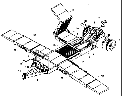
Figure 1 gives an overall perspective view with some
portions cut away or removed of the present invention shown
CA 02434716 2004-01-14
23
generally as 1. The unloading device for particulate material,
and more specifically for unloading grain from trucks and moving
it into bins, has a generally longitudinal platform 2 which is
supported at the rear end by retractable castoring transport
wheels 3 and at the front end by a hingedly connected hitch 4.
The invention has a pair of right and left ramps at the rear and
at the front. The centre portions of each of the front and rear
ramps are integrally connected and form a portion of said
platform.
In Figure 1, the rear right ramp which is foldable is marked
as 5a, while 5b has been removed for clarity of illustration.
The front pair of ramps are marked as 6a and 6b. The ramps are
parallel to one and other and spaced apart to allow a large grain
truck, in fact, even an 18-wheeler, to drive up and then down the
opposite side while unloading of material through cargo discharge
apertures located on the bottom of the truck. The truck is
generally positioned such that a discharge orifice would be
centered over the central collection bin or opening marked as 19.
Grain is moved upwards through a main auger-type conveyor
marked as 7. The grain is deposited into stationary grain
storage bins, through the tops of the bins (not shown). The main
horizontally disposed transfer conveyors are located within the
platform and move material from the discharge opening area 19.
These conveyors are marked on the right-hand side as 11 and on
the left hand side as 12. These transport conveyors 11 and 12,
in operation, move grain rearwardly to articulated smaller rear
CA 02434716 2004-01-14
24
transfer conveyors 8 and 9. The transfer conveyors 8 and 9
discharge the grain at their upper ends into the main conveyor 7.
The ramps 5a, 6a, 6b, and 5b (not shown), are hydraulically
foldable to allow narrow transport width, i.e. to move the
unloading device down highways, roads or through crowded areas.
The front right ramp 6a is actuated to a folded position by
hydraulic cylinder 13 and the left-hand side front ramp 6b is
actuated to the folded position and working position by
hydraulic cylinder 14. Linkages 15 and 16 are attached to right-
hand front ramp 6a and left-hand ramp 6b. Similar linkages and
hydraulics are found in the rear right and left ramps but are not
marked.
In order to move the device from a transport position where
it can be pulled by a power source, hydraulic cylinder 17 tilts
the rear axle and the transport wheels from an extended position
to retracted or unloading position. Clearly, platform 2 must be
secured firmly on the ground in order to avoid breakage when
large trucks move over the platform via the ramps 5a, 6a et
cetera. The movement of the ramps, transport wheels position and
hitches are all accomplished by means of hydraulics which attach
to the power source which is generally an agricultural tractor.
The power for the conveyors is provided by the power takeoff
(PTO) of the agricultural tractor. Numeral 18 indicates the
shield on the first universal joint on the PTO shaft 18a.
Hydraulic connection hoses are marked 18b.
CA 02434716 2004-01-14
25
The present invention can be actuated totally by a single
operator in the power source and there is no need for manual
lifting or moving of parts. The operator can remain at the power
source and simply move the device to the correct position and
fill one grain bin after another. The only other operator
necessary is one to drive the truck in position over the ramp and
the discharge area 19.
Moving the transport wheels from the extended to retracted
position coincides with rasing the hitch 4 and vice versa by
means of a linkage to be described later. Turnbuckles 20,
located on each side of the rear of the vehicle platform, adjust
the linkage between the two.
Figure 2 is an enlarged view of the rear of the system with
a number of other portions labelled. For example, conveyor 7 is
enclosed within conveyor tube 21 (shown in phantom). Transport
wheels 3 are supported by wheel holders 22 which are attached to
the main axle frame tube 24 that is rotated by hydraulics
cylinder 17. Pivotal joints marked 25a permit the hydraulics to
move the transport wheels 3 from a retracted to an extended
position to be shown in later drawings. Turnbuckles 20 are
attached to the platform pivotally on bell links 23. Transfer
conveyors 11 and 12 are connected to smaller rearward articulated
conveyors 8 and 9 by means of u-joints 26. The main elevating
conveyor 7 is attached to a main drive shaft by means of a lower
articulated stub section 27, which is basically the main drive CV
joint. This joint allows the axle frame member 24 to pivot
CA 02434716 2004-01-14
26
rearwardly and forwardly and not to affect the main conveyor 7.
In Figure 2, one notes the linkage to foldable right rear ramp 5a
is more clearly shown as 28.
Turning to Figure 3, one can easily view how the particulate
material is moved upwardly through the rear smaller articulated
conveyors and is discharged sideways into the main conveyor 7 by
means of orifices 29. A configuration could also be used to
discharge downwards into the main conveyor 7. The main conveyor
has a face plate 30, which is attached to the stub section of the
conveyor 27. The main conveyor pivot plate is shown as 31 which
allows for rotational movement of the stub section conveyor
casing, relative to the main conveyor casing around their
longitudinal axes. The smaller casings 10 and 10a, are pivotally
connected to the main conveyor stub tube 21 by means of
articulating brackets 33. Casings 10 and l0a are also structured
members rigidly attached to the platform. They also support the
lower end of main conveyor 7. They also support the main axle
frame tube 24. Extension and retraction of the transport wheels
3 is accomplished by rotating the main axle tube frame 24 around
pivot points 25a.
Figure 4 is a cutaway view looking downwardly at the
platform 2. There are three shafts for the augers: main auger
shaft 36; right-hand transfer auger shaft 34; and left-hand
transfer auger shaft 35. These are all moved by means of
connections to power takeoff shaft 18a which is powered by the
towing and power source, namely the agricultural tractor. These
CA 02434716 2004-01-14
27
connections are not shown in detail as these are well known in
the art.
In Figure 5, the hitch is hingable by means of a pivot hinge
38. Thus, to be discussed later, the front end of the hitch can
be raised to allow the front portion of the platform to rest on
the ground, and then lowered relative to the platform front end
for a transport position. A manual hitch-jack can be used to
move the front hitch when it is not attached to the power source.
This manual hitch-jack is shown as 39. Also shown in Figure 5 is
a safety bar 43 which prohibits an operator from falling into the
PTO shaft area.
Figure 6 is another view of the rear end of the device
looking from above and from the rear. One notes that the
conveyors 8 (not shown) and 9 are equipped with upper end plates
41.
Figures 7 and 8 show the transport position of the device
and the working or unloading position of the device respectively.
In Figure 7, the device is in the transport position. That is to
say that hitch 4 extends straight out from platform 2. Hitch 4
is attached to an agricultural tractor by tongue 4a. In Figure
7, the rear portion of the device is shown off the ground by
means of hydraulics 17 which moves the wheels 3 downwardly and
moving the rear of the platform upwardly. A link 40 connects the
hitch 4 mechanism to the transport mechanism such that when the
transport wheels are raised or lowered, similarly the hitch is
moved upwardly or downwardly about hinge pivots 38. Link 40 is
CA 02434716 2004-01-14
28
pivotally attached to the hitch at point 44 and at the rear of
the device at point 45 located on bell crank 23. Turnbuckle
attachment points 25 provide just the required amount of movement
to properly drive bell cranks (links) 23 via turnbuckles 20 to
properly move the hitch via link 40.
In order to allow the device to move to the working or
unloading position, the main axle frame tube 24 is rotated by
extension of hydraulic cylinder 17 which, at the same time,
permits platform 2 to be placed firmly on the ground. At the
same time, hitch 4 is raised at its forward end which allows the
front portion of the platform 2 to rest firmly on the ground.
The main conveyor 7 is always slightly supported above the
ground, even in the unloading position. This prevents any damage
to the articulated rear conveyors and the main conveyor 7.
Figure 9 shows a closeup of the rear end of the device in
transport position. More clearly shown are the structured
members lOb and lOc which are firmly attached to the platform and
conveyor casings 10 and l0a respectively. Hydraulics 17 are
pivotally attached at 24a and 24b.
It should be understood that conveyor casings 10, l0a and
structural members lOb, lOc and 32 do not move relative to the
platform 2. Only the main elevating conveyor 7, by means of
articulated joints 33, is able to change its angle relative to
the platform through the intermediary stub section 27.
Once the device is placed in the unloading position with the
hitch raised at its front end and the hydraulics at the rear
CA 02434716 2004-01-14
29
extended, power takeoff shaft 18a is activated and the shafts are
placed in a rotating operating position. A particulate material
transport truck is then driven over discharge opening 19 and the
grain, via the conveyors, is elevated up into a bin or other
area.
Thereafter, the process is reversed, the hydraulics
retracted, the hitch and transport wheels lowered, and the
operator can move the device to another position such that the
main auger is positioned over another grain bin. The operator
need never leave the cab of the power towing source, during
active unloading and placement of the device to another location.
The foregoing is illustrative only of the principles of the
invention. Further, since numerous changes and modifications
will occur to those skilled in the art, it is not desired to
limit the invention to the exact construction and operation shown
and described, and accordingly, all such suitable changes and
modifications in structure or operation which may be resorted to
are intended to fall within the scope of the claimed invention.
CA 02434716 2004-01-14