Note : Les descriptions sont présentées dans la langue officielle dans laquelle elles ont été soumises.
CA 02434975 2003-07-14
WO 02/097205 PCT/GB02/02254
Hanger device
The present invention relates to a hanger device used to
connect two members such as I-beams and having a
particular application in the construction industry.
It is well known within the construction industry that
wooden I-beams are used as a replacement for traditional
solid timber beams, and their usage is made all the more
popular due to their dimensional stability (no shrinkage,
cupping or distortion) and superior load-carrying
capacity (spanning capability). The wooden I-beam
typically consists of.upper.and lower flange members made
of either solid or laminated wood, and a central wood-
based web member (typically plywood or oriented strand
board) glued centrally between these upper and lower
flanges into pre-cut grooves. Examples of I-beams are
shown in Fig. 1. Typically, such beams are around 25 cm
from flange to flange, the flanges being around 4cm to
6cm wide.
The wooden I-beam is an extremely efficient structural
shape but the gap that exists between the central web
member and the upper and lower flanges makes it difficult
to connect components to them at 90 degrees.
Unfortunately, the need to connect components at 90
degrees is commonplace in domestic house construction,
where for example, floor or roof members need to be
trimmed around stair or chimney openings as shown in
Fig.2. Indeed, almost every example of domestic house
construction will require beam connections at 90 degrees
to each other.
To form a 90 degree connection to an I-beam requires the
gap between the web and both flanges to be packed or
filled with a solid material, wood for example, such that
CONFIRMATION COPY
CA 02434975 2003-07-14
WO 02/097205 PCT/GB02/02254
2
a flush surface is created of sufficient area to receive
an incoming beam or other structural member. These wood-
based packing pieces, provided to facilitate such a 90-
degree connection, are called "backer-blocks".
Where a number of beams need to be connected to a cross-
member, known as a "header", at 90 degrees, e.g. where
floor beams are trimmed around a stair opening, then
multiple backer blocks or a continuous backer block will
be required. Metal hangers are then used to connect the
incoming beams) to the supporting header beam at 90
degrees. These can either be face-fixed directly to the
backer block material or top-fixed to the upper flange of
the I-beam where less nails are required in the backer
block.
Top-fix hangers are generally used for light/medium duty
applications as they have limited load-transferring
ability but are relatively quick and easy to install.
Face-fix hangers are typically used for higher load
applications, but are generally more time consuming and
expensive to fit.
In the case of conventional face-fix connections,
multiple nails are provided through the face of the
hanger into the backer block. The backer block then
transfers the loads imparted by the hanger (from the
incoming beam) into the central web of the I-beam and
thereby into the flanges of the I-beam header.
In the case of the top-fix connection, the hanger has a
top flange, which sits on the upper edge of the header
upper flange, in addition to side flanges. In this case
nails are passed through the top and side flanges of the
hanger into the upper flange of the header, as well as
additional nails being provided through the side flanges
CA 02434975 2003-07-14
WO 02/097205 PCT/GB02/02254
3
into the backer block. As a significant amount of the
load from the hanger is being imposed eccentrically onto
one side of the header upper flange, the backer block
this time helps to prevent the upper flange from rotating
as well as transmitting load from the face of the backer
block into the central web.
However, backer blocks are rather difficult, time-
consuming and costly to install in practice. Typical
fixing specifications require backer blocks to be
provided on both sides of an I-beam web, with 6 long
nails being installed from each side with their
protruding points folded (clenched) over. Experience has
shown that this is one of the most common sources of on-
site errors when constructing I-beam floors, due to
either incorrect types or numbers of nails being used to
fix backer blocks in position.
A number of hangers are disclosed in the prior art. It
has been found that these hangers do not address the
specific problems associated with I-beams discussed above
and if used to connect I-beams in the manner discussed
above would require backer blocks to be used to assist in
load transfer and to provide a 90 degree intersection
between I-beams. Hangers of this type are more suitable
for use with solid timber beams. Much of the prior art
is concerned with general purpose hangers suitable for
use as masonary hangers. Such hangers are not designed
to be used to support I-beams and are not designed to
transfer the load experienced by I-beams.
It is therefore an object of the present invention to
address the problems outlined above as well as being able
to connect two I-beams without the need for a backer
block whilst maintaining the structural properties of a
beam connection.
CA 02434975 2003-07-14
WO 02/097205 PCT/GB02/02254
4
It is a further object of the present invention to
provide a pre-formed unitary hanger device to any given
size for use with an I-beam connection which does not
require on-site forming to secure both I-beams.
It is independently an object of the invention to improve
upon existing hanger devices in terms of the number and
arrangement of fixing apertures used for the device and
the associated reduction in cost, construction time and
waste materials which occurs as a result of the use of
this device.
In accordance with a first aspect of the invention there
is provided a hanger device for connecting together I-
beams having first and second flanges connected by a web,
the hanger comprising a first bracket having first and
second side members and an intermediate member connected
between the side members, the intermediate member being
capable of supporting a second flange of a first I-Beam,
at least one second bracket having first and second side
members and an intermediate member connected between the
side members, the first and secona slae merrwers ~~ly
provided with fixing apertures arranged thereon to
facilitate connection of the first and/or second side
members to the first and/or second flanges of a second I-
beam,
wherein the first or second side member of the first
bracket is connected to the second bracket at the first
side member thereof and at a pre-determined angle with
respect to the first side member of the second bracket.
Preferably, at least one of the first and second side
members of the first bracket are provided with fixing
apertures arranged to facilitate connection of said first
CA 02434975 2003-07-14
WO 02/097205 PCT/GB02/02254
and/or second side member to the first and/or second
flange of a first I-beam.
Preferably, the fixing apertures arranged on the first
5 and second side members of the first bracket are
positioned to provide a connection to the first and/or
second flange substantially in the centre of the flange,
the fixing apertures located on the first side member
being offset with respect to the fixing apertures on the
second side member.
Preferably, the intermediate member is provided with a
fixing aperture located substantially in the centre
thereof.
Preferably, the fixing apertures of the second bracket is
provided with a pair of diagonally arranged fixing
apertures located on the first side member being offset
with respect to a pair of diagonally arranged fixing
apertures on the second side member, for connection to
the first flange of a second I-beam at substantially in
the centre of the flange
Preferably, the fixing apertures are arranged on the
first and second side members for connection to the
second flange of a second I-beam, substantially in the
centre of the flange, with three triangularly arranged
fixing apertures located on the first side member being
offset with respect to a pair of diagonally arranged
fixing apertures on the second side member.
Optionally, the second bracket is substantially inverted
j-shaped when in use.
Optionally, the second bracket is substantially inverted
U-shaped when in use.
CA 02434975 2003-07-14
WO 02/097205 PCT/GB02/02254
6
Preferably, the device is formed from a single piece of
material.
S Preferably, the hanger is constructed from metal.
Preferably, the predetermined angle is substantially 90°.
Preferably, the first bracket is contiguous with the
second bracket.
Preferably, the first bracket is integrally formed with
said second bracket.
Preferably, at least a part of said second bracket is
pre-formed to suit the thickness of an I-beam.
In accordance with a second aspect of the present
invention there is provided a method of connecting I-
beams each having first and second flanges connected by a
web, the method comprising the steps of:
providing a hanger having first and second brackets
arranged at a predetermined angle with respect to one
another;
supporting the second flange of the first I-beam on an
intermediate member connected between first and second
side members of a first bracket and;
connecting the first and second side members of a second
bracket to the first and/or second flanges of a second I-
beam, through fixing apparatus arranged thereon.
Preferably, the step of connecting the first and/or
second flange of the first I-beam to the first and/or
second side members of the first bracket through fixing
apertures arranged thereon.
CA 02434975 2003-07-14
WO 02/097205 PCT/GB02/02254
7
In accordance with a third aspect of the invention there
is provided a,pre-formed hanger device for distributing a
load between load carrying members, said device provided
with means for connecting said members, said means
comprising a first bracket and a second bracket adjacent
thereto, said first bracket connecting to a first member
and said second bracket connecting to a second member,
wherein said second bracket is contiguous with at least a
front and back surface of said second member.
BRIEF DESCRIPTION OF THE DRAWINGS
Embodiments of the invention will now be described, by
way of example only, by reference to the accompanying
drawings, in which:
Figs la, 1b and lc are side views of typical I-beams;
Fig.2 is a perspective view of an example of the use of
I-beams in building construction.
Figs. 3a to 3h show a number of view of a first
embodiment of the present invention, Figs. 3a and 3b are
perspective views of the hanger device, Fig. 3c is a plan
view, Fig. 3d is a right hand side elevation, Fig. 3e is
a left hand side elevation and Fig. 3h is a back
elevation;
Figs. 4a and 4h show a number of views of a second
embodiment of the present invention, Figs. 3a and 3b~are
perspective views of the hanger device, Fig. 3c is a plan
view, Fig. 3d is a right hand side elevation, Fig. 3e is
a front elevation, Fig. 3f is a left hand side elevation
and Fig. 3h is a back elevation;
CA 02434975 2003-07-14
WO 02/097205 PCT/GB02/02254
8
Fig.5 shows a perspective view of the hanger device of
Fig.3b with, first and second I-beams attached thereto;
and
S Fig.6 shows a perspective view of the hanger device of
Fig. 4b with first and second I-beams attached thereto.
DETAILED DESCRIPTION OF THE EMBODIMENTS
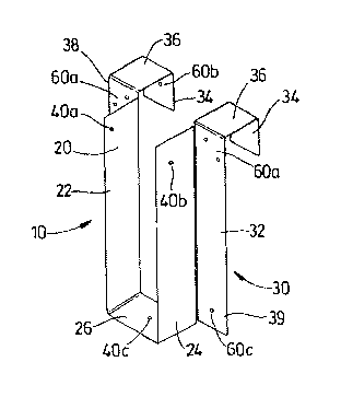
Referring to Figs. 3a and 3b of the drawings there is
shown the general arrangement of a first embodiment of
the hanger device 10 provided in accordance with the
present invention. It can be clearly seen that the
hanger 10 comprises two main brackets 20, 30, which are
contiguously formed from a unitary sheet of material.
The first bracket 20 has first and second side members
22, 24 and an intermediate member 26 connecting the first
and second side members 22, 24. In this example, the
first bracket 20 is pre-fabricated to form a generally U-
shaped bracket in which a first I-beam can be fitted. As
can be seen in Fig. 5, the I-beam is supported by
intermediate member 26 and can be further secured in the
first bracket 20 by a
pre-determined number of nails or other suitable fixing
means through fixing apertures 40 located in the first
and second side members 22, 24 and in the intermediate
member 26.
The fixing apertures 40a, 40b and 40c have been provided
at positions in the first bracket 20, which have been
found to provide structurally secure attachment to the I-
beam 80 without causing splitting of the flanges 90, 92
(Fig.5). Unlike existing hanger devices, which have a
series of fixing apertures provided over the entire
surface of the hanger to allow nails or other fixing
means to be driven into the I-beam at just about any
CA 02434975 2003-07-14
WO 02/097205 PCT/GB02/02254
9
position felt necessary, the points selected on the first
bracket for providing these fixing apertures has been
found to have a highly efficient load distribution. In
the example of the present shown in Figs 3a and 3b, the
S fixing aperture 40c is provided substantially in the
centre of the intermediate member 26. Additional fixing
apertures 40a and 40b are located in the upper portions
of side members 22, 24. In addition, the fixing
apertures 40a and 40b located in side members 22, 24 are
off-set with respect to one another, this reduces the
risk that holes in the second flange 92 will cause the
second flange 92 to split.
These hangers are designed to distribute loads in such a
way as to avoid the need for backer blocks on 90 degree
connections to wood I-beams, and thereby to eliminate the
associated fixing costs and sources of site error
involved.
The hanger 10 has an inverted j-shaped second bracket 30,
having first and second side members 32 and 34 and an
intermediate member 36 as shown which can wrap around the
top flange of the I-beam and fit snugly to 3 faces of it.
As with the first bracket 20, fixing apertures 60a and
60b are provided into the first side member 32, fixing
aperture 60c is provided in the second side member 34.
The fixing apertures are designed to receive nails or
other fixing means. The position of the fixing apertures
60a, 60b and 60c has been set to ensure that the bracket
30 is connected to the centre of each of the I-beam
flanges. In addition, the apertures 60a and 60b located
on the first and second side members 32, 34 are off-set
with respect to one another. In this example, the fixing
apertures are arranged in a diagonal pattern at the top
end 38 of the second bracket 30. A single fixing
CA 02434975 2003-07-14
WO 02/097205 PCT/GB02/02254
aperture 60c being arranged at the bottom end 39 of the
second flange 30.
Figs. 3c to 3h provide details of the positioning of 4mm
5 fixing apertures on the hanger 10. In this example,
fixing aperture 40c is provided in the centre of the
intermediate member 26, 23mm from the first side member
22. Fig. 3d shows fixing aperture 40a positioned 20mm
from the top edge and side edge of the first side member
10 22 and the position of fixing aperture 40b on the second
side member positioned lOmm from the top edge and side
edge of the second side member 24. The position of these
fixing apertures 40a and 40b is also shown in Fig. 3f.
Fig. 3e is a front elevation showing diagonally arranged
fixing apertures 60a, the lower apertures 60a being
positioned 30.5mm below the intermediate member 36 and
9mm from the outer edge of the side member 30, the upper
aperture being positioned l4mm below the intermediate
member 36 and 25.2mm from the outer edge of the side
member 30. The position of fixing aperture 60b in side
member 34 is shown relative to that of fixing aperture
60a. This fixing aperture is positioned 25mm from the
outer sides of side member 34 and 23.3mm from the
intermediate member thereof. The back elevation Fig. 3h
also shows the fixing apertures 60a, 60b and 60c from the
opposite side to that shown in Fig. 3e. Fixing aperture
60c is 2lmm from the outer edge 52 of the side member 32
and 20mm from the bottom edge 54 thereof.
In general, the position of the fixing apertures has been
selected to minimise the number of nails required as the
use of nails or other similar fixing means weakens the
flanges.
CA 02434975 2003-07-14
WO 02/097205 PCT/GB02/02254
11
This arrangement enables a substantial amount of load to
be transferred to both the front and back faces of the I-
beam top flange 192, and the resultant even distribution
of load thereby serves to delay the onset of top flange
rotation without the need for a backer-block to serve the
same purpose. The hanger device of the present invention
is therefore capable of transmitting equal or higher
loads onto supporting beams than can be transmitted by
conventional top-fix I-beam hangers, without the need for
backer blocks to be provided to delay the onset of top-
flange header beam rotation. The associated savings in
site labour time by removing the need to fix backer
blocks are considerable. In addition the hanger 10 has
equal or less nail fixings than a conventional top-fix I-
beam hanger, and is therefore just as easy and quick to
install.
Figs. 4a and 4b show a second embodiment of the present
invention. Here, similar reference numerals have been
used to describe previously described features. This
hanger 100 uses a similar load distribution principle as
the hanger 10 of the first embodiment, but the second
bracket 130 is extended to be substantially an inverted
U-shape. This allows connection to both flanges 194, 196
of a second I-beam (as can be seen in Fig.6).
The bracket 130 wraps around the top flange of the second
I-beam and extends downwardly to be fixed to the lower
flange of the I-beam. By nailing the hanger to both the
front and reverse side of the lower flange 194 of the I-
beam, the load is transferred substantially uniformly
(concentrically) into the centre of the top flange 196 of
the I-beam and thereby directly into its central vertical
plane. The majority of the load is supported at the
bottom end 139 of the second bracket. Consequently, a
greater number of fixing apertures 60 are provided on the
CA 02434975 2003-07-14
WO 02/097205 PCT/GB02/02254
12
first and second sides of the bracket 132, 134 at this
point.. In this embodiment, three triangularly arranged
fixing apertures 60 are located on the first side member
134 and are offset with respect to a pair of diagonally
arranged fixing apertures 60 on the second side member
132.
The tendency for top flange rotation is thereby almost
removed, and this phenomenon is instead transferred to a
much lesser degree to the bottom flange. The rotation of
the bottom flange 194 in turn is counter-acted by nailing
on opposing sides of the lower flange to restrain this
tendency. The resulting connection is capable of
transferring loads equal or exceeding those of
conventional face-fix I-beam hangers, but without the
need for backer-blocks to transfer the loads from the
outer face into the central web of the header. In
addition, as with the previous embodiment, the hanger of
Fig. 4 has less nail fixings than a conventional face fix
I-beam hanger and is therefore quicker and easier to
install.
Figs. 4c to 4f provide details of the positioning of 4mm
fixing apertures on the hanger 100.
In this example, the fixing aperture 40c is provided in
the centre of the intermediate member 126, 19.5mm from
the front thereof. Fig. 4d shows fixing aperture 40a
positioned lOmm from the top and the side edges of side
member 122. Fixing aperture 40b being 20mm from the top
and side edges of side member 124. The position of
fixing aperture 40b is shown to illustrate the relative
position of these fixing apertures.
These fixing apertures are also shown in Fig. 4f.
CA 02434975 2003-07-14
WO 02/097205 PCT/GB02/02254
13
Figs. 4e and 4g show the position of the fixing apertures
on .the side member 132, 134 of the second bracket 130.
Apertures 60f are arranged in a triangular formation,
16.2mm, 30.2mm and 33.2mm from the outer edges 150 of
side members and 25mm, l3mm and 33mm, respectively, from
the bottom edges. The diagonally arranged fixing
apertures 60g are arranged 13.2mm and 30.7mm from the
outer edges 150 of the side members and 9mm and
l8mm,respectively, from the bottom edges 152. The
position of fixing aperture 60g is shown to illustrate
the relative position of fixing apertures 60g and 60f.
While certain modifications and variations have been
described above, the invention is not restricted thereto
and other modifications and variations can be adopted
without departing from the scope of the invention.