Note : Les descriptions sont présentées dans la langue officielle dans laquelle elles ont été soumises.
CA 02435259 2003-07-15
Attorney Docket No. TR-174-CA
METHOD AND APPARATUS FOR OPERATING VARIABLE OPTICAL
ATTENUATOR BI' MODULATING THE ATTENUATION THEREOF
Related Application
[0001] This invention claims benefit from U.S. Provisional Patent Application
Serial
No. 601441,4$0 to Scarth, G.B., et al, entitled "Operating eVOA By
l~Iodulating Its
Attenuation", and filed on 22 January 2003.
Field of the Invention
[00021 This invention relates generally to optical teleco~rnmunications
networks and, in
particular, to a method and apparatus for operating variable optical
attenuator by modulating
the attenuation thereof.
Background of the Invention
[00031 In modern wavelength division multiplexing (WDM) networks, a loss-of-
signal
(LOS) condition causes signal power spikes that result in degradation in
signal-to-noise ratio
(SNR), increase in bit error rate (BER} and damage of downstream optical
components. To
compensate for unexpected power spikes of optical signals propagating in a WDM
network,
an electrically controlled variable optical attenuator (eVOA) (coupled with
power monitoring
and microcontroller apparatus) is typically inserted in the path of an
incoming signal for each
wavelength. The attenuator's setting is usually adjusted to a pre-determined)
fixed value
which may or may not be sufficient to reduce and/or eliminatf: the unexpected
signal power
spikes.
1
CA 02435259 2003-07-15
Attorney ~ocket No. TR-174-CA
[0004] A typical prior art eVOA apparatus includes an eVOA followed by an
optical
tap coupler for detecting the power of the optical signal at an output of the
eVOA. The
eVOA and the optical tap coupler are connected to a microcontroller. The
microcontroller
uses feedback from the optical tap coupler to control the eVO.A attenuation to
achieve a
constant output optical power. In this architecture, a loss-of-signal (LOS)
condition is
declared when the signal measured at the output of the optical tap coupler
drops below a loss-
of signal (LOS) power threshold.
[0005] Prior art offers numerous eVOA control mechanisms for handling a loss-
of-
signal (LOS) condition, wherein the eVOA attenuation is held at a fixed
attenuation when a
LOS condition is detected. Both US patent 6,207,949 entitled, "Method and
apparatus for
stabilizing attenuators in optical networks" to Jacket, J., issued on March
27, 2001, and US
patent 6,304,347 entitled, "Optical power management in an optical network" to
Beine, T., et
al, issued on October 16, 2001 ) teach that the eVOA attenuation has to be
kept at a constant
attenuation that is less than the maximum attenuation of the eVOA. This leads
to an
exposure to potential disruption or damage of downstream optical components in
the event of
a sudden power spike in the WDM network, when said constant less than
rnrdximum
attenuation is not sufficient to attenuate the power spike.
[0006] Figure I shows a diagram 100 illustrating an operation and a control
problem of
a prior art eVOA apparatus when an eVOA attenuation is kept at fixed non-
maximum
attenuation during a LOS condition. Referring to Figure I, graphs (a), (b),
and (c) are for an
input power versus time, an output power versus time and eVOA attenuation
versus time,
respectively. In graph (a), at time t I , the input power 110 is removed and
then reapplied after
2
CA 02435259 2003-07-15
Attorney Docket Plo. TR-174-CA
a specified time period t2, where the input optical power 115 is much higher.
Between times
t1 and t2 the input power 112 is zero. This may correspond, e.g., to the
cleaning of a dirty
patch cable, which is causing unwanted attenuation. In graph (c), before time
t1, the eVOA
attenuation is set at non-maximum attenuation 153. When tha input power I 10
in graph (a) is
removed (that is at time t1), the eVOA control circuit maintains the eVOA
Gtttenuation at non-
maximum attenuation 157 between times t1 and t2 and at attenuation 190 between
times t2
and t3. The eVOA minimum attenuation (MinAtt) 155 and maximum attenuation
(MaxAtt)
175 are shown in graph (c). Referring now to graph (b), before tune t1, the
output power 163
is a valid optical signal power (that is output signal power above the LOS
power threshold).
Between times t1 and t2, the output power 167 is dropped below the LOS power
threshold
165. Then, at time t2, when the patch cord is reinserted, the output power
spike 130 surges
significantly above the previous output power 163, as shown in graph (b). This
output power
spike 130 in graph (b) lasts until the microcontroller detects the presence of
optical power and
attenuates the eVOA so as to reach the steady state output power 160.
[0007] Figure 2 shows a diagram 200 illustrating limitations of the priar art
apparatus
that prevent holding the eVOA attenuation at its maximum attenuation.
Referring to Figure
2, graphs (a), (b), and (c) are for an input power versus time, an output
power versus time and
eVOA attenuation versus time respectively. In graph (a), at time t1, the
optical input power
2 0 210 is removed and then restored after a specified time period t2, where
the input optical
power 215 is much higher. Between times t1 and t2 the input I>ower 212 is
zero. In graph
(c), before time t1, the eVOA attenuation 290 is set at the non-maximum
attenuation 295.
When the input power 210 in graph (a) is removed (that is at time t1), the
eVOA control
circuit maintains the eVOA attenuation 290 at the maximum attenuation (MaxAtt)
275
3
CA 02435259 2003-07-15
Attorney Docket No. TR-174-CA
between times t1, t2, and t3. The eVOA minimum attenuation (MinAtt) 255 and
maximum
attenuation (MaxAtt) 275 are shown in graph (c). Referring now to graph (b),
before time t1,
the output power 230 is a valid optical signal power (that is output signal
power above the
LOS power threshold). Between times t1 and t2, the output power 235 is below
the L05
power threshold 265, while the eVOA attenuation 290 is set to the maximum
attenuation
(MaxAtt) 275 in graph (c). Between times t2 and t3, the output power 240 is
azlso below the
LOS power threshold 265 and thus, the microcontroller never determines if
there is sufficient
optical power at the input to the eVOA.
[0008 Prior art US patent 6,304,347 also teaches an apparatus that has an eVOA
coupled to two optical tap couplers that are connected to a microcontroller.
One optical tap
coupler leads the eVOA for detecting the power of the optical signal at an
input to the eVOA
and another optical tap coupler follows the eVOA for detecting the power of
the optical
signal at an output of the eVOA. This apparatus allows the microcontroller to
monitor the
optical signal power at the input to the eVOA and at the output of the eVOA.
1f a LOS
condition is declared when the signal measured at the input to the eVOA, the
optical tap
coupler drops below a LOS power threshold. This overcomes the problems
surrounding the
prior art apparatus described above with an optical tap coupler following the
eVOA. The
eVOA may be kept at a maximum attenuation without risk of failing to detect
the presence of
2 0 the optical signal power, but at the expense. of having an additional
optical tap and monitoring
the signal power at both input and output of the eVOA.
From a cost perspective it is desirable to use the eVOA apparatus with only
one
optical tap coupler that follows the eVOA to save the cost of another optical
tap coupler that
4
CA 02435259 2003-07-15
Attorney Docket No. TR-174-CA
is before the eVOA. Having only one optical tap coupler that follows an eVOA
also saves
physical space and electrical power on the line card where the; circuitry is
housed.
(0010) Unfortunately, none of the existing prior art apparatus provides an
effective and
reliable operation of eVOA, while minimizing the number of optical components
being used.
[0011) Accordingly, there is a need for the development of improved methods
and
apparatus for power control in optical control systems and WDM networks, which
would
reduce and/or avoid the shortcomings and limitations of the prior art.
Summary of the Invention
[0012) It is an object of the present invention to provide a method and
apparatus for
operating an eVOA by modulating its attenuation so as to provide reliable
protection of
optical components against power spikes while minimizing the number of optical
components utilized by the eVOA apparatus. It is another obje;.t of the
invention to provide
operation and control of multiple eVOAs by one microcontroller, wherein each
eVOA is
being controlled by modulating its attenuation.
[0013) The invention, therefore, according to one aspect provides a method for
operating an electronically controlled variable optical attenuator (eVOA)
inserted in an
optical path of an optical signal propagating in an optical network, the
method comprising the
steps of monitoring an optical signal power at an output of the eVOA; if the
optical signal
power is below a loss of signal (LOS) power threshold, modulating the
attenuation of the
eVOA, the modulating comprising decreasing and increasing the eVOA attenuation
in steps
5
~, , . . .,n. ~ , ~~r ,, , ~y ._~ ,. ,~ .., r w. .. "~_._. ~.~,.,~_~ .
~_.,._...a
CA 02435259 2003-07-15
Attorney Docket N~. TR-174-CA
until the optical signal power is detected above the LOS power threshold or a
maximum
eVOA attenuation is reached. The step of monitoring comprises a step of
setting the
attenuation of the eVOA to a maximum attenuation (MaxAtt} if the measured
optical signal
power is below the L OS power threshold and a step of operating the eVOA so as
to maintain
said optical signal power if the measured optical signal power is above the
LOS power
threshold. The step of monitoring the eVOA attenuation comprises a step of
storing said
eVOA attenuation.
[0014] The step of modulating the eVOA attenuation by decreasing and
increasing the
l0 attenuation in steps comprises a step of determining a maximum number of
steps "S1" for
decreasing the attenuation, a maximum number of steps "S2" for increasing the
attenuation,
an attenuation value per step " Ar ", and a predefined protection attenuation
(PPA). The step
of modulating the eVOA attenuation in steps comprises a step of stepping down
and
decreasing the attenuation by A~ , wherein { MaxAtt - PPA ) <_ S, ~ A.S. , and
a step of stepping
up and increasing the attenuation by A_~. , wherein { SZ ~ A.y. f PPA ) <_
MaxAtt. The step of
decreasing and increasing the eVOA attenuation in steps comprises a step of
checking for a
valid optical measured power at the output of said eVOA, the valid optical
measured power
being a signal measured power above the LOS power threshold.
2 o [0015] In accordance with a first embodiment of this invention, the
apparatus for
operating an electronically controlled variable optical attenuator (eVOA)
inserted in an
optical path of an optical signal propagating in an optical network comprising
a
microcontroller for monitoring an optical signal power at an output of the
eVOA and
modulating the attenuation of the eVOA if the optical signal power is below a
loss of signal
6
CA 02435259 2003-07-15
Attorney ~ocket fro. TR-174-CA
{LOS) power threshold, the modulating being performed as decreasing and
increasing of the
eVOA attenuation in steps until the optical signal power is detected above the
LOS power
threshold or a maximum eVOA attenuation is reached.
[0016] Another aspect of this invention provides a method of operating a
plurality of
eVOAs inserted in optical paths of optical signals propagating in an optical
network,
comprising the steps of:
[0017] (a) selecting an eVOA from the plurality of eVOAs;
[0018] (b) operating the selected eVOA according to the method described above
for
the first embodiment of this invention within a time period allocated for the
selected eVOA;
[0019] {c) repeating the steps (a) to (b) until all eVOA.s from the plurality
of eVOAs
have been selected; and
[0020] (d) repeating the steps (a) to (c) as required.
[0021] The step of monitoring a plurality of eVOAs attemuations comprises a
step of
continuously cycling said eVOAs in a specified time period "T', wherein "T" is
a sum of all
time periods { t; and i=1, n}, "n" is the number of eVOAs, and n >l, and t; is
the time for
actively controlling each eVOA. Further, for equal allocated time period per
eVOA, wherein
t, = t2= t; =t"=z , z = T/n, and ~ is the time for actively controlling each
eVOA. The step
of cycling a plurality of eVOAs comprises a step of taking a finite time "T,."
for each step,
and z = S, ~ Ts < ~ , wherein "T,." being the expected optical control system
power transient
' n
time, and S, is the maximum number of steps for decreasing the eVOA
attenuation. Also,
the step of cycling a plurality of eVOAs comprises a step of taking a finite
time "T." for each
CA 02435259 2003-07-15
Attorney Docket No. TR-174-CA
step, and Z = S~ -TS. < T , wherein S~ is the maximum number of steps for
increasing the
eVOA attenuation.
[0022) In accordance with a second embodiment of this invention, the apparatus
for
operating a plurality of eVOAs in an optical network comprises a
microcontroiler having a
means for selecting an eVOA from the plurality of eVOAs; and a means for
operating the
selected eVOA according to the method for the first embodiment of this
invention within a
time period allocated for the selected eVOA.
[0023) The embodiments of the invention provide a method for modulating the
eVOA
attenuation by stepping down and decreasing the attenuation or stepping up and
increasing the
attenuation until a valid optical measured power at the output of said eVOA is
detected,
wherein the valid optical measured power being a signal measured power above
the LOS
power threshold.
[0024) The embodiments of the invention provide improved method and apparatus
for
operating an eVOA by modulating its attenuation. Additionally, if multiple
eVOAs to be use,
the method also allows a microcontroller to operate a multiplicity of eVOAs
while
minimizing the risk of damage to the WDM network components that would
overcome the
2 0 shortcomings and limitations of the prior art.
Brief Description of the Drawings
[0025] The invention is better understood from the following description of a
preferred
embodiment together with reference to the accompanying drawing, in which:
8
~, ,. , . , .",~.. ., , _ . ." ~ .. ,._" ... .. ~. . , d... . .. , . _ ~. . ,
~. .~. . __ .
CA 02435259 2003-07-15
attorney Docket No. TR-i 74-CA
[0026] Figure I is a diagram illustrating a dependence of input power, output
power and eVOA attenuation versus time for a prior art eVOA apparatus
when the eVOA attenuation is kept at a non-maximum level;
[0027] Figure 2 is at diagram illustrating a dependence of input power, output
power and eVOA attenuation versus time for the prior art eVOA apparatus
when the eVOA attenuation is kept at the maximum level;
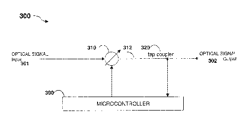
[0028] Figure 3 illustrates an eVOA apparatus in accordance with a first
embodiment of this invention;
[0029] Figure 4. is a diagram illustrating a stepping cycle of the eVOA 310 of
the
eVOA apparatus of Figure 3;
[0030] Figure 5 is a flow chart diagram illustrating a method of operating the
eVOA apparatus of Figure 3;
[0031] Figure S illustrates multiple eVOA apparatus in accordance with a
second
embodiment of this invention;
[0032] Figure 7 is a diagram illustrating a microcontroller cycling time slots
for
the multiple eVOAs apparatus in Figure 6;
9
CA 02435259 2003-07-15
Attorney ~ocket No. TR-174-CA
[0033] Figure 8 is a flow chart diagram illustrating a method of operating the
multiple eVOAs apparatus of Figure 6;
[0034] Figure 9 is a diagram illustrating a dependence of input power, output
power and eVOA attenuation versus time for the multiple eVOA apparatus
of Figure 6 when each eVOA is operating according to the prior art
methods; and
[0035] Figure 10 is another diagram illustrating a de,pendenc:e of input
power,
output power, and eVOA attenuation versus time for the multiple eVOAs
apparatus of Figure 6, while operating accordaing to the method of Figure 8.
Description of the Preferred Embodiments
[0036] Figure 3 shows an eVOA apparatus 300 of the first embodiment for
operating an
electronically controlled variable optical attenuator (eVOA) connected to a
microcontroller
390, the eVOA 3l0 is inserted in optical signal path of an optical channel in
a wavelength
division multiplexed (WDM) network. Referring to Figure 3, an optical tap
coupler 320
follows the eVOA 310 inserted in an incoming optical signal path 301, both the
optical tap
coupler 320 and the eVOA 3 i 0 are connected to a microcontroller 390 for
monitoring and
2 0 controlling the eVOA attenuation. The optical tap coupler 320 is used for
detecting the
power of the optical signal 302 at the output 312 of the eVOA 310. The optical
tap coupler
320 is calibrated to accurately report the output signal power 302 at an
output of the eVOA
310. This is done during the manufacturing process by placing an optical power-
meter at the
optical signal output and recording the photodetector response versus power
over a range of
CA 02435259 2003-07-15
Attorney docket No. TR-174-CA
powers. The output of the optical tap coupler 320 is processed by the
microcontroller 390 to
determine small and finite steps for controlling the eVOA 310 attenuation. The
LOS power
threshold is calibrated during commissioning of the installed optical control
system to meet
the requirements of the WDM network. The microcantraller 390 monitors and sets
the
attenuation of the eVOA 310.
[0037] The eVOA 310 is held at its maximum attenuation when the output
measured
power 302 is below the LOS power threshold. The microcontroller 390
continuously
monitors for the presence of optical power (that is output measured power
above the LOS
power threshold). The eVOA 310 attenuation is also periodically decreased and
then
increased for a certain period of tune to check for the presence of optical
measured power at
the output 312 of the eVOA 310. l~f no optical measured power is detected, the
eVOA 310
attenuation is returned to the maxi~~num attenuation. If, at any time, optical
measured power
is detected, normal control is restored (that is operating the eVOA 310 at the
optical
measured power).
[0a383 Figure 4 illustrates a stepping cycle (decreasing and increasing) 400
for the
eVOA 310 attenuation in small and finite steps to sense for the presence of
optical measured
power. Figure 4 shows a dependence of the eVOA 310 attenuation on which a
minimum
2 0 attenuation (MinAtt) 480 and a maximum attenuation (MaxAtt) 470 are shown.
The
microcontroller 390 of the apparatus of Figure 3 is repeatedly decreasing or
increasing the
eVOA 3l0 attenuation (unless optical measured power is detected) within a time
period T
425. The decrease and increase in eVOA 310 attenuation is done in a series of
small and
finite steps to some predefined value (which may be the predefined protection
attenuation
11
CA 02435259 2003-07-15
Attorney Docket No. TR-174-CA
(PPA) 460 if desired). The number of steps "S", and attenuation per step, AS
430 can be
chosen judiciously but the product S - As 43S must be less than the difference
between the
maximum attenuation (MaxAtt) 470 and the predefined protection attenuation
(PPA) 460.
Each step takes a finite time, TS 440 where S - TS 450 is less than T 425. The
value of T~ 440
is minimized within the physical limitations of the optical control system and
is limited by the
response time of the microcontroller 390 and the slew rate of the eVOA 310
attenuation.
Generally, T~ 440 is on the order of the expected optical control system power
transients
(typically but not limited to around 1-l0ms}.
t o [00391 Thus, the eVOA 310 is held at an attenuation that is not the
maximum for a
fraction of time, (S - T~) and it is held at a maximum attenuation (MaxAtt)
470 for the
remaining period of time, namely, {T- (S -Ts)}. The value T 425 is kept
reasonably small to
maintain a reasonable fast response time of the microcontroller. As an
illustration, for a value
of time period, T=I second, a number of steps S=4, and a time period per step
Ts = l Oms, the
eVOA apparatus 300 provides a decrease in power spikes risk of { 1-(S - Ts/T)
=96% }
compared to prior art. The step size, As 430 is chosen to provide an
acceptable power
transient to downstream components. For example, a value of relative power
ratio of 0.5
(representing a decrease in attenuation of 50%) or -3dB on a log scale
provides an acceptable
power transient, while, for example, -20dB may be excessive in certain
situations.
as
[0040] While the optical power risk may be characterized as a function of both
the
optical power of a transient and the length of time during which that
transient is present, it
can be seen that the optical power applied prior to the initiation of the
stepping cycle would
introduce only a low-powered transient (contained by the step value AS 430),
while optical
la
CA 02435259 2003-07-15
Attorney Docket No. TR-174-CA
power applied during the stepping cycle may possibly introduce a higher-
powered transient,
but only for a limited time period (contained by the stepping time interval TS
440).
j0041] The number of steps ''S" is chosen such that the f>roduct S ~ As 435
allows the
mierocontroller 390 to detect sufficiently small optical powers, as dictated
by the optical
control system requirements. Tl;.e number of steps "S" is equal to a maximum
number of
steps "S," for decreasing the attenuation or a maximum number of steps "S2 "
for increasing
the attenuation, wherein S, ~ S~ .
[0042] Figure 5 is a flow chart diagram 500 illustrating a method for
operating the
eVOA apparatus 300 of Figure 3. The normal operating attenuation of an eVOA
310 is
monitored and stored by the microcontroller 390. The method 500 is
incorporated on the
microcontroller 390 for controlling the eVOA 37 0 attenuation, wherein upon
start up (block
506); routine 507 initializes the eVOA 310 control circuit parameters (block
510). The
parameters comprise an eVOA maximum attenuation (MaxAtt) 51 I, a number of
steps for
decreasing the eVOA attenuation S, 512, a number of steps for increasing the
eVOA
attenuation SZ 5120, an attenuation value per step As SI3, and a pre-defined
value for
protection attenuation (PPA) 514. Routine 507 uses actual measured power
{Pmeas} (block
520) at an output of an eVOA (block 515). If a loss-of signal (LOS) condition
is detected
(block 525), routine 507 sets the eVOA 3I0 attenuation to a maximum
attenuation (MaxAtt
51 I) (block 530). If a valid measured power is detected (block 535), routine
507 operates the
eVOA 310 at the valid measured power (block 550), (that is normal control is
restored); if a
valid measured power is detected below a LOS power threshold (block 535),
routine 507
decreases the eVOA 310 attenuation (block 570) by AS 513, increases the number
of steps by
13
CA 02435259 2003-07-15
Attorney Docket No. TR-1 ~4-CA
one (block 560), and checks for a valid measured power above the LOS power
threshold
(block 535). If the valid measured power is detected to be below the LOS power
threshold
and the maximum defined number of steps S, 512 is reached (block 563), and if
{ MaxAtt -
PPA >_ S, ~ AS} (block 540), routine 507 increases the eVOA attenuation (block
580) by AS
513, and checks again for a valid measured power above the LOS power threshold
(block
535). If a valid measured power is detected below the LOS power threshold
(block 535) and
tire maximum defined number-of steps S~ 5120 is reached (block 563), and if {
SZ ~ AS + PPA
>_ MaxAtt} (block 545), routine 507 resets the eVOA 310 attenuation to the
maximum
attenuation (MaxAtt 5I 1 ) (block 530). Periodically, the attenuation is
reduced or increased in
steps for short intervals to minimize the risk of a high-power transient being
introduced to
downstream components.
[0043] Figure 6 shows a multiple eVOA apparatus 600 of the second embodiment
for
operating a plurality of eVOAs connected to a microcontroller 690, wherein the
plurality of
eVOAs 610, 630, 650 and 670 follow by a plurality of optical tap couplers 620,
640, 660 and
680 respectively connected to the microcontroller 690. The plurality crf eVOAs
may include
"n" eVOAs, wherein n > I . In Figure 6, the optical tap couplers 620, fi40,
660 and 680
follow a plurality of eVOAs 610, 630, 650 and 670 inserted in the path of
incoming optical
signals 601, 603, 605 and 607 respectively. The optical tap couplers 620, 640,
660 and 680
are used for detecting the power of the respective optical signalls 602, c~04,
606 and 608 at the
outputs of the eVOAs 610, 630, 650, and 670 correspondingly. The optical tap
couplers 620,
640, 660 and 680 are calibrated to accurately report the respective output
signals powers 602,
604, 606 and 608. As described above, this is done during the manufacturing
process by
placing an optical power-meter at the optical signal output of each eVOA and
recording the
14
CA 02435259 2003-07-15
Attorney Docket No. TR-174-CA
photodetector respome versus power over a range of powers. 'The LOS power
threshold is
calibrated during commissioning of the installed optical system to meea the
requirements of
the optical network. The outputs of the optical tap couplers 602, 604, 606 and
608 are
processed by a microcontroller 690 to determine small and finite steps for
controlling the
attenuations of the eVOAs 610, fi30, 650 and 670. The microcontroller 690
monitors and sets
the attenuation of the eVOAs 610, 630, 650 and 670.
[0044] Figure 7 shows a diagram 700 illustrating a microcontroller time
division
multiplexing for the "n" eVOAs, wherein the number of eVOAs ''n" is equal to
four, as
shown in Figure 6. The microcontroller 690 actively monitors. and controls one
eVOA circuit
at-a-time. The microcontroller 690 time divisions multiplexes its control
amongst the eVOAs
610, 630, 650 and 670 circuits it services, wherein the order o1F the eVOAs
610, 630, 650 and
670 can be arbitrary or in certain sequence, as required. The microcontroller
690
continuously cycles its control through each circuit within a time period, T
720, wherein T
720 is a sum of all time periods ( t; and i=1, ..., n}, "n" is the number of
eVOAs, and n >1,
and t; is the time for actively controlling each eVOA. fn cas~° wherein
each of the "n"
eVOAs circuits is being actively controlled for a time, i 730 and 740, the
value "n - i "<= T
720, and t, = t2= t; =t"=z , 2 = T/n, and 2 is the time for actively
controlling each eVGA.
For stepping up, the microcontroller's 690 cycling of the plurality of eVOAs
610, 630, 650
and 670 takes a finite time "T,." for each step, and z= S, ~ T, ' T , wherein
"T,." being the
n
expected optical control system power transient time, and S, is the maximum
number of
steps for decreasing each eVOA attenuation. For stepping down, the
microcontroller's 690
cycling of the plurality of eVOAs 610, 630, 650 and 670 takes a finite time
"T,." for each
CA 02435259 2003-07-15
Attorney Docket No. TR-17~t-CA
step, and 2= SZ ~T. < ~ , wherein "~'~." being the expected optical control
system power
T2
transient time, and S~ is the maximum number of steps for increasing the eVOA
attenuation.
[o045~ Figure 8 is a flow chart diagram 800 illustrating a method for
operating the
multiple eVOAs apparatus 600 of Figure 6, wherein upon start up (block 806),
routine 807
initializes the parameters (block 810) for each eVOA. The parameters comprise
an eVOA
maximum attenuation (MaxAtt) 81 l,-a maximum number of steps for decreasing
the eVOA
attenuation S, 812, a maximum number of steps for increasing tlhe eVOA
attenuation S
8120, an attenuation value per step AS 813, and a pre-defined value for the
protection
attenuation (PPA} 814. Routine 807 uses actual measured power {Pmeas} (block
820) at an
output of an eVOA (block 815). When a LOS power condition (block 825) is
detected on a
given channel at an output of an eVOA, routine 807 sets said eVOA attenuation
to a
maximum attenuation (MaxAtt 817 ) (block 830). If a valid measured power is
detected
(block 835), routine 807 operates the eVOA at the valid measure°d power
(block $50}, (that is
normal control is restored); if a valid measured power is detected below a LOS
power
threshold (block 835), routine 807 decreases the eVOA attenuation (block 870)
by AS 813,
increases the number of steps by one (block 860), and checks for a valid
measured power
above the LOS power threshold (block 835). If the valid measur ed power is
detected to be
below the LOS power threshold and the maximum defined number of steps S, 812
is reaclhed
(block 863}, and if {MaxAtt-PPA >_ S, - AS} (block 840), routiine 807
increases the eVO.A
attenuation (block 880) by AS 813, and checks again for a valid measured power
above the
LOS power threshold (block 835). If a valid measured power is detected below
the LOS
power threshold (block 835) and th:e maximum defined number of steps SZ 8120
is reached
16
CA 02435259 2003-07-15
Attorney ~ocket No. TR-174-CA
(block 863), and if { S., ~ A5 -t- PPA >_ MaxAtt{ (block 845), routine 807
resets the eVOA
attenuation to the maximum attenuation (MaxAtt 81 I) (block 830). The
microcontroller 690
cycles through each channel, monitoring and adjusting each eVOA as required.
When the
microcontroller 690 returns its attention to the channel with a LOS condition,
it checks for a
valid optical measured power above a LOS power threshold (block 835). If the
optical
measured power is below the LOS power threshold, it decreases (block 870) or
increases
(block 880) the attenuation by a predetermined step, and checks again for a
valid optical
measured power above the LOS power threshold (block 835). If the optical
measured power
is below the LOS power threshold. it again decreases (block 870) or increases
(block 880) the
attenuation by a predetermined step and checks for a valid optical measured
power above the
LOS power threshold (Block 835). This procedure continues for a number of
steps, S~ 812
and SZ 8l 20 (or until a valid optical measured power above the LOS power
threshold is
observed). If a valid optical measured power below the LOS power threshold is
observed
(block 835), the eVOA attenuation is set to the maximum attenuation (MaxAtt
811 ) (block
25 830) and the microcontroller 690 then proceeds (block 890 next eVOA) to the
next channel
(Block 805).
]0046] The flow chart 800 repeats the same procedure for all eVOAs, selecting
one
eVOA out of eVOAs 610, 630, 650 and 670 at a time for processing (via dotted
line loop
2 0 including box 890).
(0047] Figure 9 shows a diagram 930 illustrating the optical control system
behaviour
for a microcontroller 690 monitoring a multiplicity of eVOAs when each eVOA is
controlled
according to the prior art methods. Referring to Figure 9, graphs (a), (b),
and (c) are for an
17
CA 02435259 2003-07-15
Attorney Docket No. TR-174-CA
input power versus time, an output power versus time and the eVOA aattenuation
versus time,
respectively. In graph (a), at time t1, the input power 920 is removed and
then reapplied after
a specified time period t2, where the input optical power 925 i;s much higher.
Between tmmes
t1 and t2 the input power 923 is zero. In graph (c), before timE: fl, the eVOA
attenuation is
set at the non-maximum attenuation 973. When the input power 920 in graph (a)
is removed
(that is at time t1 ), each eVOA control circuit maintains its eVOA
attenuation at non-
maximum attenuation 977 between times t1 and t2 and 955 between times t2 and
t3. The
eVOA minimum attenuation (MinAtt) 970 and maximum attenuation (lVlaxAtt) 980
are
shown in graph (c). Graph (c) also shows the specified time periods, 961, 963,
965 and 967
for actively monitoring and controlling one eVOA circuit at-a-time. The
microcontroller 690
continuously cycles its control through each circuit within said specified
time period.
Referring now to graph (b), before time fl, the output power 930 is a valid
optical signal
power (that is output signal power above the LOS power threshold). lBetween
times fl and t2,
the output power 933 is dropped below the LOS power threshold 935. Then, at
time t2, when
the input power 920 in graph (a) is reapplied, the output power spike 945
surges significantly
above the previous output power' 930, as shown in graph (b). 'I~his output
power spike 945 in
graph (b) lasts until the microcoatroller detects the presence of optical
power and attenuates
the eVOA so as to reach the steady state output power 947. In this case, the
duration of the
optical power spike is increased by a significant amount and the maximum time
is
approximately (n-1)-i, wherein ~s is the specified time period 961, 96.3, 965
and 967, and "n"
is the number of eVOAs, where "'n" is equal four in this example.
(0048] Figure 10 shows a diagram 1000 illustrating the optical control system
behaviour for a microeontroller ~i90 incorporating the method of Figure 8
described above.
18
CA 02435259 2003-07-15
Attorney Docket No. TR-174-CA
Referring to Figure 10, graphs (a), (b), and {c) are for an input power versus
time, an output
power versus time, and the eVOA attenuation versus time, respectively. In
graph (a), at time
t I, the input power 1023 is removed and then reapplied after a specified time
period t2, where
the input optical power 1025 is much higher. Between times t 1 and t2 the
input power 1027
is zero. In graph (c), before time t1, the eVOA attenuation is set at the non-
maximum
attenuation 1075. When the input power 1023 in graph (a) is removed (that is
at time t I ), the
eVOA control circuit maintains its eVOA attenuation 1073 at its maximum
attenuation 1080.
The eVOA minimum attenuation (MinAtt) 1070 and maximum attenuation (MaxAtt)
1080
are shown in graph (c). The microcontroller 690 cycles the eVOAs 610, 630, 650
and 670
circuits, decreases or increases the eVOA attenuation in steps 1'.077 and
1079, and controls
each eVOA for a time period 1061, 1063, 1065 and 1067 as shown in graph (c).
Referrirsg
now to graph (b), before time t1, the output power 1033 is a valid optical
signal power (that is
output signal power above the LOS power threshold). Between times t1 and t2,
the output
power 1036 is below the LOS power threshold 1035 and between times t2 and t3,
the output
power 1045 is above the LOS power threshold 1035 and has no spikes. In this
case, the
eVOA attenuation 1055 in graph (c) eliminates the power spike in the output
power 1045 in
graph (b). Accordingly, the method of this invention eliminates the power
spike in the output
power 1045 as shown in graph (b).
2 0 [0049] Thus, the embodiments of the invention provide a method and
apparatus for
operating an eVOA by modulating its attenuation, wherein the attenuation
periodically and
quickly decreased and/or increased in steps while checking for the presence of
optical signals
above the LOS power threshold.
19
CA 02435259 2003-07-15
Attorney docket No. TR-174-CA
[0050] The embodiments also provide a method of operating a multiplicity of
eVOAs,
while minimizing the risk of damage to optical network equipment.
[0051 It will be apparent to those with skill in the art that modifications to
the above
methods and embodiments can occur without deviating from the scope of the
present
invention. Accordingly, the disclosures and descriptions herein are intended
to be illustrative,
but not limiting, of the scope of the invention which is set forth in the
following claims.