Sélection de la langue

Search

Sommaire du brevet 2436100 

Énoncé de désistement de responsabilité concernant l'information provenant de tiers

Une partie des informations de ce site Web a été fournie par des sources externes. Le gouvernement du Canada n'assume aucune responsabilité concernant la précision, l'actualité ou la fiabilité des informations fournies par les sources externes. Les utilisateurs qui désirent employer cette information devraient consulter directement la source des informations. Le contenu fourni par les sources externes n'est pas assujetti aux exigences sur les langues officielles, la protection des renseignements personnels et l'accessibilité.

Disponibilité de l'Abrégé et des Revendications

L'apparition de différences dans le texte et l'image des Revendications et de l'Abrégé dépend du moment auquel le document est publié. Les textes des Revendications et de l'Abrégé sont affichés :

  • lorsque la demande peut être examinée par le public;
  • lorsque le brevet est émis (délivrance).
(12) Brevet: (11) CA 2436100
(54) Titre français: CHASSIS POUR LE TRANSPORT D'UN PASSAGER
(54) Titre anglais: PASSENGER CARRIER FRAME
Statut: Périmé et au-delà du délai pour l’annulation
Données bibliographiques
(51) Classification internationale des brevets (CIB):
  • B62B 07/06 (2006.01)
  • B62B 07/10 (2006.01)
(72) Inventeurs :
  • BRITTON, DANIEL WILLIAM (Canada)
  • ASSAF, IMAD (Canada)
(73) Titulaires :
  • THULE CHILD TRANSPORT SYSTEMS LTD.
(71) Demandeurs :
  • THULE CHILD TRANSPORT SYSTEMS LTD. (Canada)
(74) Agent: BENNETT JONES LLP
(74) Co-agent:
(45) Délivré: 2011-07-12
(22) Date de dépôt: 2003-07-14
(41) Mise à la disponibilité du public: 2005-01-14
Requête d'examen: 2008-06-25
Licence disponible: S.O.
Cédé au domaine public: S.O.
(25) Langue des documents déposés: Anglais

Traité de coopération en matière de brevets (PCT): Non

(30) Données de priorité de la demande: S.O.

Abrégés

Abrégé français

Châssis de dispositif de transport d'un passager comprenant un élément inférieur, un élément pliant, un élément de dossier et une commande de pliage. Ces éléments sont joints de manière pivotante les uns aux autres près de leurs extrémités de manière à former un triangle lorsqu'ils sont vus de côté. Les articulations pivotantes permettent au châssis d'être plié, et la commande de pliage du châssis agit sur l'articulation pivotante choisie pour entraîner la rotation en pivot de cette articulation et la bloquer.


Abrégé anglais

A passenger Garner frame of the invention includes a lower frame member, a folding frame member, a back frame member and a frame folding control. These frame members are pivotally connected adjacent their ends to form a triangular arrangement in side view. The pivotal connections permit the frame to be folded and the frame folding control acts at a selected one of the pivotal connections to drive and lock pivotal rotation at that pivotal connection.

Revendications

Note : Les revendications sont présentées dans la langue officielle dans laquelle elles ont été soumises.


11
What is claimed is:
1. A passenger carrier frame comprising: a lower frame member; a folding frame
member
including a folding joint; an upper frame member, the frame members having
pivotal
connections to connect them adjacent their ends to form a triangular
arrangement in side view
and the pivotal connections and the folding joint together permitting the
frame to be folded; and
a frame folding control acting at a selected one of the pivotal connections to
drive rotation at that
pivotal connection to cause folding and unfolding of the frame and actuatable
to lock against
rotation at that pivotal connection and the frame folding control including a
folding link
including a first link portion pivotally fixed to the upper frame member and a
second link portion
pivotally fixed to the folding frame member and a link pivotal connection
between the first link
portion and the second link portion, the folding link being actuatable to lock
by locking the link
pivotal connection against pivotal movement.
2. The passenger carrier frame of claim 1 wherein the frame folding control
drives the
folding frame member to collapse inwardly about the joint toward the lo*er
frame member, such
that the upper frame member and the lower frame member fold together with the
folding frame
member disposed therebetween.
3. The passenger carrier frame of claim 1 wherein the second link portion is
pivotally fixed
to the folding frame member within the end 25% of the folding frame member
length.
4. The passenger carrier frame of claim 1 further comprising means supporting
the
attachment of transport means.
5. The passenger carrier frame of claim 1 wherein the first link portion is
formed as a lever
including an end extending beyond the pivotal connection, the frame folding
control being
actuatable to lock by means of a releasable latch between the lever and the
upper frame member.
6. The passenger carrier frame of claim 5 wherein the frame is formed to
accommodate a
handlebar for construction of a pushable carrier and the handlebar is
connectable to the lever of
the frame folding control.

12
7. The passenger carrier frame of claim 5 wherein the frame folding control
drives rotation
at the selected pivotal connection to cause unfolding of the frame by rotating
the lever toward the
selected pivotal connection.
8. A passenger carrier frame comprising: a first frame member; a second frame
member
pivotally connected to the first frame member; a folding frame member
including a first pivotal
connection to the first frame member, a second pivotal connection to the
second frame member
and a joint positioned between the first pivotal connection and the second
pivotal connection and
a frame folding control connected between the second frame member and the
folding frame
member to control pivotal movement about the second pivotal connection, the
frame folding
control being lockable to fix the frame members against pivotal movement about
the second
pivotal connection and unlockable to permit pivotal rotation at the second
pivotal connection
such that the second frame member and the folding frame member can pivot about
the second
pivotal connection and the folding frame member can collapse about the joint
and the frame
folding control driving the folding frame member to collapse inwardly about
the joint toward the
first frame member, such that the second frame member and the first frame
member fold together
with the folding frame member disposed therebetween.
9. The passenger carrier frame of claim 8 further comprising means supporting
the
attachment of transport means.
10. The passenger carrier frame of claim 8 wherein the frame folding control
includes a
folding link including a first link portion pivotally fixed to the second
frame member and a
second link portion pivotally fixed to the folding frame member and a link
pivotal connection
between the first link portion and the second link portion, the folding link
being lockable by
locking the link pivotal connection against pivotal movement.
11. The passenger carrier frame of claim 10 wherein the first link portion is
formed as a lever
including a pivotal connection to the second frame member and a handle at an
end opposite the
pivotal connection with the link pivotal connection fixed therebetween, the
frame folding control
being lockable by means of a releasable latch between the lever and the second
frame member.

13
12. The passenger carrier frame of claim 11 wherein the frame is formed to
accommodate a
handlebar for construction of a pushable carrier and the handlebar is
connectable to the lever of
the frame folding control.
13. The passenger carrier frame of claim 11 wherein the frame folding control
is unlockable
by rotating the lever toward the first frame member.
14. The passenger carrier frame of claim 10 wherein the second link portion is
pivotally fixed
to the folding frame member within the end 25% of the folding frame member
length.
15. A passenger carrier frame comprising: a first frame member; a second frame
member
pivotally connected to the first frame member; a folding frame member
including a first pivotal
connection to the first frame member, a second pivotal connection to the
second frame member
and a joint positioned between the first pivotal connection and the second
pivotal connection and
a frame folding control connected between the second frame member and the
folding frame
member to control pivotal movement about the second pivotal connection, the
frame folding
control being lockable to fix the frame members against pivotal movement about
the second
pivotal connection and unlockable to permit pivotal rotation at the second
pivotal connection
such that the second frame member and the folding frame member can pivot about
the second
pivotal connection and the folding frame member can collapse about the joint
and the frame
folding control including a folding link including a first link portion
pivotally fixed to the second
frame member and a second link portion pivotally fixed to the folding frame
member and a link
pivotal connection between the first link portion and the second link portion,
the folding link
being lockable by locking the link pivotal connection against pivotal
movement.
16. The passenger carrier frame of claim 15 wherein the frame folding control
drives the
folding frame member to collapse inwardly about the joint toward the first
frame member, such
that the second frame member and the first frame member fold together with the
folding frame
member disposed therebetween.
17. The passenger carrier frame of claim 15 wherein the second link portion is
pivotally fixed
to the folding frame member within the end 25% of the folding frame member
length.

14
18. The passenger carrier frame of claim 15 further comprising means
supporting the
attachment of transport means.
19. The passenger carrier frame of claim 15 wherein the first link portion is
formed as a lever
including a pivotal connection to the second frame member and a handle at an
end opposite the
pivotal connection with the link pivotal connection fixed therebetween, the
frame folding control
being lockable by means of a releasable latch between the lever and the second
frame member.
20. The passenger carrier frame of claim 19 wherein the frame is formed to
accommodate a
handlebar for construction of a pushable carrier and the handlebar is
connectable to the lever of
the frame folding control.
21. A passenger carrier frame comprising: a first frame member forming a base
of the
passenger carrier; a second frame member pivotally connected to the lower
frame member and
extending upwardly therefrom; a folding frame member including an upper end, a
lower end and
a joint therebetween about which the folding frame member can be folded, the
folding frame
member being pivotally connected adjacent its lower end to the first frame
member; an upper
frame pivotal connection adjacent the upper end of the folding frame member,
the upper frame
pivotal connection providing a pivotally moveable connection between the
folding frame
member and the second frame member; and a frame folding control connected
between the
folding frame member and the second frame member to control pivotal movement
about the
upper frame pivotal connection, the frame folding control being lockable to
fix the upper frame
pivotal connection against pivotal movement and unlockable to permit pivotal
rotation at the
upper frame pivotal connection such that the folding frame member and the
second frame
member can pivot about the upper frame pivotal connection and the folding
frame member can
collapse about the joint, and the frame folding control including a folding
link including a first
link portion pivotally fixed to the second frame member and a second link
portion pivotally fixed
to the folding frame member and a link pivotal connection between the first
link portion and the
second link portion, the folding link being lockable by locking the link
pivotal connection
against pivotal movement.
22. The passenger carrier frame of claim 21 wherein the second frame member
forms the
upper rear portion of the frame and the folding frame member is positioned
forwardly thereof.

15
23. The passenger carrier frame of claim 21 wherein the frame folding control
drives the
folding frame member to collapse inwardly about the joint toward the first
frame member, such
that the second frame member and the first frame member fold together with the
folding frame
member disposed therebetween.
24. The passenger carrier frame of claim 21 wherein the second link portion is
pivotally fixed
to the folding frame member within the end 25% of the folding frame member
length.
25. The passenger carrier frame of claim 21 further comprising means
supporting the
attachment of transport means.
26. The passenger carrier frame of claim 21 wherein the first link portion is
formed as a lever
including a pivotal connection to the second frame member and an end opposite
the pivotal
connection with the link pivotal connection positioned therebetween, the frame
folding control
being lockable by means of a releasable latch between the lever and the second
frame member.
27. The passenger carrier frame of claim 26 wherein the frame is formed to
accommodate a
handlebar for construction of a pushable carrier and the handlebar is
connectable to the lever of
the frame folding control.
28. The passenger carrier frame of claim 26 wherein the folding frame control
is unlockable
by rotating the lever toward the first frame member.
29. A passenger carrier frame comprising: a first frame member forming a base
of the
passenger carrier; a second frame member pivotally connected to the first
frame member and
extending upwardly therefrom; a folding frame member including an upper end, a
lower end and
a joint therebetween about which the folding frame member can be folded, the
folding frame
member being pivotally connected adjacent its lower end to the first frame
member; an upper
frame pivotal connection adjacent the upper end of the folding frame member,
the upper frame
pivotal connection providing a pivotally moveable connection between the
folding frame
member and the second frame member; and a frame folding control connected
between the
folding frame member and the second frame member to control pivotal movement
about the
upper frame pivotal connection, the frame folding control being lockable to
fix the upper frame
pivotal connection against pivotal movement and unlockable to permit pivotal
rotation at the

16
upper frame pivotal connection such that the folding frame member and the
second frame
member can pivot about the upper frame pivotal connection and the folding
frame member can
collapse about the joint, the frame folding control driving the folding frame
member to collapse
inwardly about the joint toward the first frame member, such that the second
frame member and
the first frame member fold together with the folding frame member disposed
therebetween.
30. The passenger carrier frame of claim 29 wherein the second frame member
forms the
upper rear portion of the frame and the folding frame member is positioned
forwardly thereof.
31. The passenger carrier frame of claim 29 further comprising transport means
attached
thereto.
32. The passenger carrier frame of claim 29 wherein the frame folding control
includes a
folding link including a first link portion pivotally fixed to the second
frame member and a
second link portion pivotally fixed to the folding frame member and a link
pivotal connection
between the first link portion and the second link portion, the folding link
being lockable by
locking the link pivotal connection against pivotal movement.
33. A passenger carrier frame comprising: a lower frame member; a folding
frame member
including a folding joint; an upper frame member, the frame members having
pivotal
connections to connect them adjacent their ends to form a triangular
arrangement in side view
and the pivotal connections and the folding joint together permitting the
frame to be folded; and
a frame folding control acting at a selected one of the pivotal connections to
drive rotation at that
pivotal connection to cause folding and unfolding of the frame and actuatable
to lock against
rotation at that pivotal connection and the frame folding control driving the
folding frame
member to collapse inwardly about the joint toward the lower frame member,
such that the upper
frame member and the lower frame member fold together with the folding frame
member
disposed therebetween, the frame folding control including a folding link
including a first link
portion pivotally fixed to the upper frame member and a second link portion
pivotally fixed to
the folding frame member and a link pivotal connection between the first link
portion and the
second link portion, the folding link being actuatable to lock by locking the
link pivotal
connection against pivotal movement.

17
34. The passenger carrier frame of claim 33 further comprising means
supporting the
attachment of transport means.
35. A passenger carrier frame comprising: a first frame member forming a base
of the
passenger carrier; a second frame member pivotally connected to the lower
frame member and
extending upwardly therefrom; a folding frame member including an upper end, a
lower end and
a joint therebetween about which the folding frame member can be folded, the
folding frame
member being pivotally connected adjacent its lower end to the first frame
member; an upper
frame pivotal connection adjacent the upper end of the folding frame member,
the upper frame
pivotal connection providing a pivotally moveable connection between the
folding frame
member and the second frame member; means for supporting the attachment of
transport means;
and a frame folding control connected between the folding frame member and the
second frame
member to control pivotal movement about the upper frame pivotal connection,
the frame
folding control being lockable to fix the upper frame pivotal connection
against pivotal
movement and unlockable to permit pivotal rotation at the upper frame pivotal
connection such
that the folding frame member; the second frame member can pivot about the
upper frame
pivotal connection and the folding frame member can collapse about the joint.
36. The passenger carrier frame of claim 35 wherein the second frame member
forms the
upper rear portion of the frame and the folding frame member is positioned
forwardly thereof.
37. The passenger carrier frame of claim 35 wherein the frame folding control
drives the
folding frame member to collapse inwardly about the joint toward the first
frame member, such
that the second frame member and the first frame member fold together with the
folding frame
member disposed therebetween.
38. The passenger carrier frame of claim 35 wherein the frame folding control
includes a
folding link including a first link portion pivotally fixed to the second
frame member and a
second link portion pivotally fixed to the folding frame member and a link
pivotal connection
between the first link portion and the second link portion, the folding link
being lockable by
locking the link pivotal connection against pivotal movement.

18
39. The passenger carrier frame of claim 38 wherein the first link portion is
formed as a lever
including a pivotal connection to the second frame member and an end opposite
the pivotal
connection with the link pivotal connection positioned therebetween, the frame
folding control
being lockable by means of a releasable latch between the lever and the second
frame member.
40. The passenger carrier frame of claim 39 wherein the frame is formed to
accommodate a
handlebar for construction of a pushable carrier and the handlebar is
connectable to the lever of
the frame folding control.
41. The passenger carrier frame of claim 38 wherein the second link portion is
pivotally fixed
to the folding frame member within the end 25% of the folding frame member
length.
42. The passenger carrier frame of claim 40 wherein the folding frame control
is unlockable
by rotating the lever toward the first frame member.
43. A passenger carrier frame comprising: a lower frame member; a folding
frame member
including a folding joint; an upper frame member, the frame members having
pivotal
connections to connect them adjacent their ends to form a triangular
arrangement in side view
and the pivotal connections and the folding joint together permitting the
frame to be folded;
means supporting the attachment of transport means; and a frame folding
control acting at a
selected one of the pivotal connections to drive rotation at that pivotal
connection to cause
folding and unfolding of the frame and actuatable to lock against rotation at
that pivotal
connection.
44. The passenger carrier frame of claim 43 wherein the frame folding control
drives the
folding frame member to collapse inwardly about the joint toward the lower
frame member, such
that the upper frame member and the lower frame member fold together with the
folding frame
member disposed therebetween.
45. The passenger carrier frame of claim 43 wherein the frame folding control
includes a
folding link including a first link portion pivotally fixed to the upper frame
member and a second
link portion pivotally fixed to the folding frame member and a link pivotal
connection between
the first link portion and the second link portion, the folding link being
actuatable to lock by
locking the link pivotal connection against pivotal movement.

19
46. The passenger carrier frame of claim 45 wherein the first link portion is
formed as a lever
including an end extending beyond the pivotal connection, the frame folding
control being
actuatable to lock by means of a releasable latch between the lever and the
upper frame member.
47. The passenger carrier frame of claim 46 wherein the frame is formed to
accommodate a
handlebar for construction of a pushable carrier and the handlebar is
connectable to the lever of
the frame folding control.
48. The passenger carrier frame of claim 45 wherein the second link portion is
pivotally fixed
to the folding frame member within the end 25% of the folding frame member
length.
49. The passenger carrier frame of claim 46 wherein the frame folding control
drives rotation
at the selected pivotal connection to cause unfolding of the frame by rotating
the lever toward the
selected pivotal connection.

Description

Note : Les descriptions sont présentées dans la langue officielle dans laquelle elles ont été soumises.


CA 02436100 2003-07-14
PASSENGER CARRIER FRAME
Field of the Invention
The present invention relates to a passenger Garner frame and, in particular,
a foldable frame for
a passenger carrier such as a stroller, a jogger or a trailer, as for a
bicycle or hiker.
Background of the Invention
In recent years, consumers with active lifestyles have sought passenger
carriers that are rugged
and versatile. Passenger carriers such as strollers or trailers, such as for
towing behind a bicycle
or by a hiker, must be foldable for transport and storage, while being easy to
unfold.
Since many passenger carriers have frames that require complicated alignment
and pinning of
frame components, a frame is needed that is durable and foldable but easy to
manipulate.
Summary of the Invention
A foldable passenger carrier frame has been invented that is durable and easy
to fold for storage
and transport, but can be unfolded readily for use.
In accordance with a broad aspect of the present invention, there is provided
a passenger carrier
frame comprising: a first frame member; a second frame member pivotally
connected to the first
frame member; a folding frame member including a first pivotal connection to
the first frame
member, a second pivotal connection to the second frame member and a joint
positioned
between the first pivotal connection and the second pivotal connection and a
frame folding
control connected between the second frame member and the folding frame member
to control
pivotal movement about the second pivotal connection, the frame folding
control being lockable
to fix the frame members against pivotal movement about the second pivotal
connection and
unlockable to permit pivotal rotation at the second pivotal connection such
that the second frame
C:\NrPortbl\DMSIxgal\CALDWELLR\1572882_1.DOC

CA 02436100 2003-07-14
2
member and the folding frame member can pivot about the second pivotal
connection and the
folding frame member can collapse about the joint.
For ease of handling, the frame folding control can be positioned on an upper
portion of the
frame. Thus, in accordance with a broad aspect of the present invention, there
is provided a
passenger carrier frame comprising: a first frame member forming a base of the
passenger
earner; a second frame member pivotally connected to the lower frame member
and extending
upwardly therefrom; a folding frame member including an upper end, a lower end
and a joint
therebetween about which the folding frame member can be folded, the folding
frame member
being pivotally connected adjacent its lower end to the first frame member; an
upper frame
pivotal connection adjacent the upper end of the folding frame member, the
upper frame pivotal
connection providing a pivotally moveable connection between the folding frame
member and
the second frame member; and a frame folding control connected between the
folding frame
member and the second frame member to control pivotal movement about the upper
frame
pivotal connection, the frame folding control being lockable to fix the upper
frame pivotal
connection against pivotal movement and unlockable to permit pivotal rotation
at the upper
frame pivotal connection such that the folding frame member and the second
frame member can
pivot about the upper frame pivotal connection and the folding frame member
can collapse about
the joint.
The frame folding control can be selected to cause the folding frame member to
collapse
inwardly about the joint toward the first frame member. This causes the second
frame member
to fold down to overlie the first frame member with the folding frame member
disposed
therebetween.
In one embodiment, the frame folding control is a folding link including a
first link portion
pivotally fixed to the second frame member and a second link portion pivotally
fixed to the
folding frame member and a link pivotal connection between the first link
portion and the second
link portion, the folding link being lockable by locking the link pivotal
connection against
pivotal movement.
In one such embodiment, the first link portion is formed as a lever including
a pivotal connection
to the second frame member and a handle at an end opposite the pivotal
connection with the link
C:WrPortbl\DMSLegal\CALDWELLR\1572882_1.DOC

CA 02436100 2003-07-14
3
pivotal connection fixed therebetween and the frame folding control is
lockable by means of a
releasable latch between the lever and the second frame member.
The frame can be formed to accommodate a handlebar for construction of a
stroller. In one
embodiment, the handlebar is connectable to the lever of the frame folding
control.
In an embodiment selected for ease of handling and aerodynamics, the second
frame member
forms the upper rear portion of the frame, while the folding frame member is
positioned
forwardly thereof.
The frame, in one embodiment, is formed of elongate members, such as tubes,
rods or bars
(which together will be referred to herein as tubes) wherein, for example, the
folding frame
member are formed of a pair of side tubes with a joint correspondingly
positioned on each to
permit folding thereof. A cross member can be provided between the pair of
side tubes. It is
advantageous that any cross members are positioned adjacent the tube ends, for
example within
the end 25% of the full tube length. This provides a maximum open area on the
frame to reduce
obstructions for access to the passenger compartment defined between the first
second and
folding frame members.
The frame can include means supporting the attachment of transport means.
Brief Description of the Drawings
A further, detailed, description of the invention, briefly described above,
will follow by reference
to the following drawings of specific embodiments of the invention. These
drawings depict only
typical embodiments of the invention and are therefore not to be considered
limiting of its scope.
In the drawings:
Figure 1 is a perspective view of a frame according to the present invention
in an upright
configuration for use. The illustrated frame is fitted with a handlebar for
use in a pushable frame
such as a stroller or a jogger;
Figure 2 is a perspective view of the frame of Figure 1 in the initial stages
of folding. The frame
is shown with the wheels removed in order to facilitate understanding.
C: W rPortbl\DMSLegal\CALD W ELLRU 572882_1.DOC

CA 02436100 2003-07-14
4
Figure 3 is a side elevation of the frame of Figure 2.
Figure 4 is a side elevation of the frame of Figure 1, in a folded
configuration for storage or
transport. The frame is illustrated with the handlebar removed.
Figure 5 is a perspective view of the frame of Figure 4.
Figure 6 is an enlarged side elevation of the latching system included in the
frame of Figure 1,
the latching system being in the unlatched position.
Figure 7 is an enlarged side elevation of the latching system of Figure 6, in
the latched position.
Figure 8 is an enlarged perspective view of another latching system useful in
the present
invention, the latching system being in the unlatched position.
Figure 9 is a view corresponding to Figure 8 with the latching system in a
configuration
approaching latching.
Figure 10 is a view corresponding to Figures 8 and 9 with the latching system
in a latched
position.
Detailed Description of the Invention
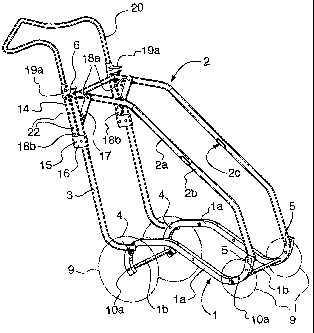
Refernng to Figures 1 to 5, a passenger carrier frame according to the present
invention is
shown. The frame is useful for various passenger carrier configurations such
as, for example, a
stroller, a bicycle or hiker trailer, a jogger, a wheel chair, etc. and the
illustrated frame is
convertible between various of these forms. In Figures 1 to 3, the frame is
shown fitted with a
handlebar such that it is suitable for incorporation into a stroller or a
jogger, which is moved by
pushing on the handlebar. The frame can be formed specifically without a
handlebar fitting
capability, and could resemble that frame of Figures 4 and 5. Such a frame,
for example, would
be useful for incorporation into a trailer.
The frame of the illustrated embodiments includes a lower frame member 1, a
folding frame
member 2 and a back frame member 3. These frame members are pivotally
connected adjacent
their ends to form a triangular arrangement in side view. In particular, back
frame member 3 is
C:WrPortbl\DMSLegaI\CALDWELLR\1572882_1.DOC

CA 02436100 2003-07-14
pivotally connected by pins 4 to lower frame member 1, folding frame member 2
is pivotally
connected by pins 5 to lower frame member 1 and back frame member and folding
frame
member are pivotally connected by pins 6.
Folding frame member 2 includes two sections 2a, 2b attached through a joint
2c. When
released to act, joint 2c allows the upper section 2a of the folding frame
member to rotate relative
to the lower part 2b.
The pivotal connections provided through pins 4, 5, 6 and joint 2c maintain
the frame members
in connected form and are arranged to act in parallel axes so that rotation
can occur about all of
the connections to permit folding of the frame.
The pivotal movement at pins 4, 5, 6 and joint 2c can be provided through
various forms, such as
pins, bolts, hinges, flexible inserts, etc. However, the pins and joints
should be durable and able
to support the weight of the frame and folding substantially without shearing
and failing
immediately. Folding, to at least some degree, can be permitted through joint
2c in various
configurations (i.e. a direct pinning or bolting, a ball joint, a flexible
polymeric insert, a hinge,
etc.) and at various positions along the length of the folding frame member.
However, joint 2c is
preferably formed to permit a 180° range of movement between sections
2a and 2b, as this
permits a very compact folding arrangement. In the illustrated embodiment, the
joint is formed
by links 7 connected at one end by pins 8a to section 2a and at the other end
by pins 8b to
sections 2b. Note as well that the joint can be formed at a number of
positions along frame
member 2, (i.e. in the middle 80% of the length) while still permitting
folding to some degree.
However, positioning the joint substantially centrally (i.e. in the middle 20%
of the length)
between the connections at pins 5 and 6 provides a convenient and compact
folding arrangement.
To be effective for passenger carrying, the frame will eventually need to be
fitted with transport
means such as, for example, four wheels, shown in phantom at 9, other numbers
of wheels, skis
or towing hitches. The frame can, therefore, be fitted with apertures l0a
(Figure 1) or lOb
(Figure 4) for accepting the mounting of transport components, brackets,
connectors, or other
means for supporting attachment of the transport means.
C:WrPortbl\DMSLegaIiCALDWELLR\1572882_1.DOC

CA 02436100 2003-07-14
6
Also to be effective for passenger carrying the frame will eventually need to
support a seat into
which a passenger can be secured. However, to facilitate illustration the seat
has not been
shown. It is to be understood that the seat can be configured in various ways
such as, for
example, by slinging between various of the upper frame members or by forming
the seat into
the lower frame member. When incorporated into a passenger carrier the frame
may also support
an outer covering, storage compartments, cowlings, etc.
The passenger carrier frame further includes a frame folding control including
a lever 14 and a
link 17. Lever 14 has a fulcrum at pivot connection 15 to a clevis 16 that is
rigidly connected to
back frame member 3. Link 17 is pivotally connected at each end by pins 18a,
18b to extend
between lever 14 and folding frame member 2.
A latching mechanism including a bracket 19a and a catch 19b releasably locks
lever 14 against
rotation about its fulcrum.
Lever 14 can be formed in various ways depending on the end use of the frame.
For example, in
the embodiment of Figure 1, lever 14 is formed on each side as a sleeve to
accept insertion of a
stroller handlebar 20. Lever 14 can include spaced apertures 22 for
cooperation with spring-
loaded detent pins on the handlebar, for selection of handlebar height.
Handlebar 20 facilitates
locating and grasping lever 14. If the frame was formed specifically for use
as a trailer, it might
resemble the embodiment of Figure 4, wherein no handlebar was provided and the
lever was
formed as separate parts on each side. A cross member could be provided
between the separate
lever parts, if desired. The frame may also be useful in a passenger carrier
that is convertible
between a trailer, a stroller, a jogger, etc..
The frame folding control drives the folding and unfolding of the frame. In
particular, as lever
14 is rotated downwards about its fulcrum, pivot connection 15, as shown by
arrow A1, it pulls
link 17 downwards (arrow A2), thereby pulling on upper section 2a of the
folding frame
member. This causes the folding frame member to fold about joint 2a (arrow
A3), which results
in the rest of the frame folding simultaneously (Figures 2, 3, 4 and 5). When
folded, the frame
forms a generally cube-shaped arrangement, which is conveniently stored. In
particular,
preferably folding frame member 2 is formed to collapse inwardly, toward the
other frame
members 1, 3 so that the folded frame does not become overly long. In this
configuration, the
C:\NrPortbl\DMSLegal\CALDW ELLR\1572882_LDOC

CA 02436100 2003-07-14
7
folding frame member folds between the back frame member and the lower frame
member,
which the back frame member overlies the lower frame member. In addition, the
positioning of
handlebar 20 on lever permits the handlebar to be maintained on the frame
during storage, it
being formed to tuck in around the frame.
To upright the frame, the reverse action is carried out. In particular, lever
14 is rotated upwards
about its fulcrum toward pins 6, as shown by arrow B1, it pushes link 17
against upper section 2a
of the folding frame member. This causes the folding frame member to be pushed
out, which
results in the frame uprighting simultaneously by pivoting about pins 4, 5, 6
and joint 2c until
lever 14 locks against back frame member 3.
As will be appreciated, for proper folding and solid upright configuration,
the length of link 17
and sections 2a, 2b and the positioning of pivotal connections 18a, 18b and
joint 2c, must be
selected to correspond so that when lever is in a locked configuration, the
folding frame member
is unfolded to it upright configuration.
Other arrangements can be used in place of the illustrated lever and link
arrangement. For
example, lever can be oriented to rotate downwardly to upright the frame and
upwardly to fold
the frame. However, it is advantageous to require upward rotation of the lever
since this
corresponds with the normal unfolding motion of both the frame and the
operator. In particular,
the operator can position the folded frame on a support surface and simply
pull up on the lever to
upright the frame. This is particularly advantageous, for example, when the
frame is being lifted
out of a storage compartment, such as of a vehicle. In particular, in the same
motion of lifting
the frame from the storage compartment, the passenger carrier frame can be
unfolded, ready for
use.
As another example, the lever and link arrangement could be positioned about
the other two
frame pivotal connections at pins 4 or 5. However, the illustrated positioning
in the upper rear
corner facilitates handling, since it is positioned within easy reach of the
operator, especially
when the frame is being used in the stroller configuration. As such, when the
frame is
incorporated in a passenger carrier and in use with an operator gripping
handlebar, the operator
can drive the entire folding operation without their moving about the frame or
bending over.
C:\NrPortbl\DMSLegal\CALDWELLR\1572882-I.DOC

CA 02436100 2003-07-14
As another example, lever 14 can be pinned directly to back frame member to
rotate about the
fulcrum in various orientations. However, the clevis arrangement permits the
lever to extend
adjacent and substantially parallel with the back frame member and out of the
way of the rotation
of folding frame member about connection at pins 6. In addition, during normal
operation as a
stroller, force is most often directed through lever 14 toward the stroller
front end, forcing the
lever into latching engagement.
It should also be understood that only one lever and link need be provided to
drive the folding of
the frame about one of its pivotal connections. However, due to its tubular
construction and
symmetrical form, the frame is preferably, for frame rigidity and ease of
operation, substantially
duplicated on each side of the frame. This is also true for the latching
mechanism.
While the frame members each act as unitary parts, it is to be understood that
the frame members
can be formed, as shown, of a plurality of rigidly interconnected sections.
For example, in the
illustrated embodiment, the lower frame member is formed of a pair of elongate
side members la
that extend generally from front to back and a pair of elongate cross members
lb that rigidly
connect between side members la. Members la and lb together form lower frame
member:
Back frame member 3 includes a pair of elongate members 3a, 3b. Folding frame
member 2 is
formed of a pair of elongate side members each having a joint 2c positioned
therealong at
corresponding locations that permit folding of the overall frame member 2.
Side members 2' and
2" extend upwardly from front to back and a cross member 2' rigidly connects
therebetween at
the upper end.
The frame of the present invention permits easy folding but also provides
significant open area
for access to the passenger compartment and few obstructions to passenger
viewing areas. In
particular, the frame, when incorporated into a passenger carrier, generally
defines a passenger
compartment wherein the folding frame member forms the upper extent, the back
frame member
forms the rear extent and the lower frame member forms the base. Thus, the
present frame is
advantageous since it requires few cross members for holding the frame upright
and for driving
folding. Furthermore, any such required cross members, such as links 17 or
cross members 2',
can be restricted to positioning adjacent the frame corners out of the way of
the main open areas.
C:\NrPortbl\DMSLegal\CALDWELLR\1572882-1.DOC

CA 02436100 2003-07-14
9
For example, cross members, such as links 17 and cross member 2', can be
positioned adjacent
the ends of their frame member for example within the end 25°Io of
their frame member length.
The various elongate frame members can be formed of various rod, bar or
tubular materials and
in various shapes. While, the frame members are generally formed of tubing
formed of, for
example, aluminium or steel tubing, it is to be noted however, for example
with reference to U.S.
Patent 5,577,746 issued to the present assignee, that the frame members could
be formed of
polymeric shells or in other ways. The frame members can be curved or straight
to
accommodate appearance, space and other considerations. The frame members and
other
components can be connected together by pinning, riveting, bolting, welding,
adhesives, inserts
or other durable means. Pivotal connections can be provided by use of rivets,
bolts, pins or other
fasteners.
The latching mechanism mounts between the lever and the back frame member and
can be any
mechanism that releasably latches these parts together. Preferably, the
latching mechanism is
selected to latch automatically once the parts are brought together. For
example, one suitable
arrangement is shown in Figures 6 and 7 and another suitable arrangement is
shown in Figures 8
to 10.
First with reference to Figures 6 and 7, a latching system useful in the
present invention includes
a back frame cap defining an inclined catch 19b mounted at the top of back
frame member 3 and
a latching bracket 19a that mounts at the top end of the lever. Bracket 19a
includes an aperture
30 that sleeves around the top of lever 14. In the stroller configuration, the
upper surface 30a of
the bracket is open allowing for the insertion of the handlebar 20. When
intended for use as a
trailer, the upper surface can be capped. Bracket 19a further includes a
cavity 32 sized to fit over
and engage catch 19b. The latching bracket 19a is spring loaded to bias the
bracket axially
against the end of the lever. When driven against catch 19b, the cavity of the
latching bracket
captures the back frame cap 19b (Figure 7), preventing the lever from moving
and, thereby,
preventing the frame from folding.
To fold the frame, the latching bracket is lifted by its tabs 34 until it
completely disengages from
the catch and then the lever can be is rotated downwards to fold the frame
(Figure 6).
C:WrPortbl\DMSLegal\CALDWEL,L,RU572882-LDOC

CA 02436100 2003-07-14
To upright the, frame, lever 14 is lifted upwards to rotate about its fulcrum.
When the latching
bracket 19a comes in contact with the catch 19b, the bracket slides upward on
lever 14, as forced
by the inclined surface, until the catch aligns with cavity 32 in the latching
bracket. At that
instance, the spring in the latching bracket pulls the bracket down to capture
the catch 19b in the
cavity and to secure the lever to the back frame member, thereby locking the
frame in its upright
position.
Refernng to Figures 8 to 10, another latching mechanism is shown. The latching
mechanism
includes two brackets: a back frame bracket 36 that is fixed to back frame
member and bracket
38 that is capable of rotating around the axis of lever 14. Bracket 38 is
fitted with a torsional
spring that permits rotation of the bracket but automatically returns it to
its original position once
force is removed. Both brackets have latching features 40, 42 that lock the
two parts to each
other, preventing the frame from folding.
To fold the frame, the bracket on lever 14 is manually twisted or rotated open
by pushing on tab
44 until its latch 40 completely disengages from latch 42 on back frame
bracket 36, and then the
lever is moved downwards to fold the frame.
To Supright the frame, the lever is lifted upwards. When the two brackets 36,
38 come in contact
with each other, bracket 38 is automatically twisted or rotated open by a
flange 46 on the back
frame bracket pushing against a rib 48 on bracket 38. Once the latching
features on the two
brackets clear each other, the torsional spring in the bracket 38 twists or
rotates the bracket back
closed to secure the latching features together, thereby locking the frame in
its upright position.
The latching mechanism components, clevis members and other parts can be
formed of durable
materials such as polymers or metals, as will be appreciated.
Although preferred embodiments of the present invention have been described in
some detail
hereinabove, those skilled in the art will recognise that various
substitutions and modifications
may be made to the invention without departing from the scope and spirit of
the appended
claims.
C:WrPortbl\DMSLegal\CALDW BLLR\1572882-1.DOC

Dessin représentatif
Une figure unique qui représente un dessin illustrant l'invention.
États administratifs

2024-08-01 : Dans le cadre de la transition vers les Brevets de nouvelle génération (BNG), la base de données sur les brevets canadiens (BDBC) contient désormais un Historique d'événement plus détaillé, qui reproduit le Journal des événements de notre nouvelle solution interne.

Veuillez noter que les événements débutant par « Inactive : » se réfèrent à des événements qui ne sont plus utilisés dans notre nouvelle solution interne.

Pour une meilleure compréhension de l'état de la demande ou brevet qui figure sur cette page, la rubrique Mise en garde , et les descriptions de Brevet , Historique d'événement , Taxes périodiques et Historique des paiements devraient être consultées.

Historique d'événement

Description Date
Le délai pour l'annulation est expiré 2018-07-16
Lettre envoyée 2017-07-14
Lettre envoyée 2011-07-27
Accordé par délivrance 2011-07-12
Inactive : Page couverture publiée 2011-07-11
Inactive : Taxe finale reçue 2011-05-03
Préoctroi 2011-05-03
Un avis d'acceptation est envoyé 2011-04-04
Inactive : Lettre officielle 2011-04-04
Lettre envoyée 2011-04-04
Un avis d'acceptation est envoyé 2011-04-04
Inactive : Approuvée aux fins d'acceptation (AFA) 2011-03-31
Modification reçue - modification volontaire 2011-01-13
Inactive : Dem. de l'examinateur par.30(2) Règles 2010-07-13
Lettre envoyée 2008-07-03
Exigences pour une requête d'examen - jugée conforme 2008-06-25
Toutes les exigences pour l'examen - jugée conforme 2008-06-25
Requête d'examen reçue 2008-06-25
Inactive : CIB de MCD 2006-03-12
Modification reçue - modification volontaire 2006-01-16
Demande publiée (accessible au public) 2005-01-14
Inactive : Page couverture publiée 2005-01-13
Inactive : Correspondance - Formalités 2004-03-22
Lettre envoyée 2004-01-23
Inactive : Transfert individuel 2003-12-04
Inactive : CIB en 1re position 2003-09-30
Inactive : Certificat de dépôt - Sans RE (Anglais) 2003-09-04
Demande reçue - nationale ordinaire 2003-09-03

Historique d'abandonnement

Il n'y a pas d'historique d'abandonnement

Taxes périodiques

Le dernier paiement a été reçu le 2011-01-10

Avis : Si le paiement en totalité n'a pas été reçu au plus tard à la date indiquée, une taxe supplémentaire peut être imposée, soit une des taxes suivantes :

  • taxe de rétablissement ;
  • taxe pour paiement en souffrance ; ou
  • taxe additionnelle pour le renversement d'une péremption réputée.

Les taxes sur les brevets sont ajustées au 1er janvier de chaque année. Les montants ci-dessus sont les montants actuels s'ils sont reçus au plus tard le 31 décembre de l'année en cours.
Veuillez vous référer à la page web des taxes sur les brevets de l'OPIC pour voir tous les montants actuels des taxes.

Titulaires au dossier

Les titulaires actuels et antérieures au dossier sont affichés en ordre alphabétique.

Titulaires actuels au dossier
THULE CHILD TRANSPORT SYSTEMS LTD.
Titulaires antérieures au dossier
DANIEL WILLIAM BRITTON
IMAD ASSAF
Les propriétaires antérieurs qui ne figurent pas dans la liste des « Propriétaires au dossier » apparaîtront dans d'autres documents au dossier.
Documents

Pour visionner les fichiers sélectionnés, entrer le code reCAPTCHA :


Pour visualiser une image, cliquer sur un lien dans la colonne description du document (Temporairement non-disponible). Pour télécharger l'image (les images), cliquer l'une ou plusieurs cases à cocher dans la première colonne et ensuite cliquer sur le bouton "Télécharger sélection en format PDF (archive Zip)" ou le bouton "Télécharger sélection (en un fichier PDF fusionné)".

Liste des documents de brevet publiés et non publiés sur la BDBC .

Si vous avez des difficultés à accéder au contenu, veuillez communiquer avec le Centre de services à la clientèle au 1-866-997-1936, ou envoyer un courriel au Centre de service à la clientèle de l'OPIC.

({010=Tous les documents, 020=Au moment du dépôt, 030=Au moment de la mise à la disponibilité du public, 040=À la délivrance, 050=Examen, 060=Correspondance reçue, 070=Divers, 080=Correspondance envoyée, 090=Paiement})


Description du
Document 
Date
(aaaa-mm-jj) 
Nombre de pages   Taille de l'image (Ko) 
Description 2003-07-13 10 530
Abrégé 2003-07-13 1 14
Revendications 2003-07-13 4 196
Dessins 2003-07-13 8 175
Dessins 2004-03-21 6 212
Dessin représentatif 2004-12-19 1 19
Revendications 2011-01-12 9 485
Dessin représentatif 2011-06-08 1 19
Certificat de dépôt (anglais) 2003-09-03 1 160
Courtoisie - Certificat d'enregistrement (document(s) connexe(s)) 2004-01-22 1 107
Rappel de taxe de maintien due 2005-03-14 1 111
Rappel - requête d'examen 2008-03-16 1 119
Accusé de réception de la requête d'examen 2008-07-02 1 177
Avis du commissaire - Demande jugée acceptable 2011-04-03 1 163
Avis concernant la taxe de maintien 2017-08-24 1 182
Avis concernant la taxe de maintien 2017-08-24 1 181
Correspondance 2003-09-03 1 29
Correspondance 2004-03-21 7 237
Taxes 2005-04-17 1 28
Taxes 2006-06-08 1 31
Taxes 2007-06-27 1 35
Taxes 2008-06-24 1 43
Correspondance 2011-04-03 1 30
Correspondance 2011-05-02 1 40