Note : Les descriptions sont présentées dans la langue officielle dans laquelle elles ont été soumises.
CA 02436363 2003-07-25
WO 02/063125 PCT/GB02/00213
1
Title: A Door Closer
Description of and Background to the Invention
This invention concerns door closers of the kind comprising an actuator
assembly intended for concealed fitting within the thickness of a door, and an
anchor member for fixing to a door frame, and in which an operating member is
coupled to said anchor member and is movable within the actuator assembly
under the action of driving means, usually comprising one or more mechanical
springs, and under the control of a fluid-filled damper (usually uni-
directionally
operative) which serves to regulate the rate of movement of the door in the
direction of closure without significantly restricting the rate of movement of
the
door in the direction of opening.
Tt is desirable for the action of any damper in such a door closer to be
adjustable so as to enable the rate of closure to be set to fall within a
chosen range
despite variations in the weight and other parameters of different doors with
which the closer may be used, and for the closer to provide an augmented
closing
force as the door reaches its closed position in order to overcome resistance
from
any Iatch fitted to the door. It is also desirable, and often necessary, from
a
product performance viewpoint, that the arrangement employed to provide such
an augmented closing force is able to operate smoothly over a very large
number
of repeated uses.
Summary of the Prior Art
EP 0 016 445 A discloses a door closer in which adjustment of the final
part of the closure movement of the door is achieved by means of an adjustment
member associated with the anchor member which is attached to the door frame,
the adjustment member being disposed behind a mounting plate of the anchor
member at a variable spacing so as effectively to adjust the length of the
coupling
between the anchor member and the operating member in the actuator assembly.
CA 02436363 2003-07-25
WO 02/063125 PCT/GB02/00213
2
This arrangement does not make any provision for adjustment of the overall
rate
of closure, but only in the final closure position of the door relative to a
final part
of the travel of the piston in the door-closing direction, in which final part
of the
travel the action of the damper is rendered ineffective so as to provide for a
locally increased rate of closure movement to overcome any resistance which
may be offered by a door latch for example.
Although the rate of movement of the door as it approaches its position of
closure is increased, there is no provision for adjusting the driving force
applied
to the door over the final part of closure movement, as relieving the effect
of the
damper does not increase the force applied by the driving springs, but only
allows
the door to accelerate in response to the driving force and the closing action
then
relies on the momentum of the moving door to overcome latch resistance.
However, the acceleration achieved depends on many variable factors, including
the weight of the door, wind loading on the door, and frictional resistance in
the
hinges and in the latch itself, and accordingly such a design does not
entirely
address the problem of overcoming resistance associated with a door latch.
DE 1 708 349 A discloses a door closer having a main spring which acts
over the full range of movement of a rod which is coupled by a link to an
anchor
member, and a supplementary spring arranged end to end with the main spring
which is effective to increase the driving force applied to the rod over the
final
part of the closure stroke, but without provision for varying the point at
which the
supplementary spring becomes effective.
WO 00/52291 discloses a door closer having a pair of thrust springs which
are operative to increase the closing force exerted on the door as the door
reaches
its closed position, the point at which the thrust springs come into effect
being
adjustable, so that variations in the width of the gap between an inner edge
of the
door and the door frame may be compensated for. The arrangement which is
employed to restrain/release the thrust springs utilises a plurality of balls
moveable radially within a cage to engage in grooves in moveable components.
CA 02436363 2003-07-25
WO 02/063125 PCT/GB02/00213
3
Accordingly, it is an object of the present invention to provide an
improved door closer which enables an augmented closure force to come into
play as the door approaches its position of closure, and which provides for
adjustment of the operation to suit a wide range of requirements. It is also
an
object of the present invention to provide an improved control means which
controls the application of the augmented closure force.
Summary of the Invention
According to a first aspect of the invention we provide a door closer
comprising:-
an anchor member for mounting on a door frame,
an actuator assembly for mounting within the thickness of a door which is
hinged for movement between open and closed positions relative to said door
frame,
an operating member coupled by an articulated link to said anchor
member and mounted in said actuator assembly for a range of movement between
a retracted position in which said anchor member is held adjacent to said
actuator
assembly and an extended position in which said anchor member is held in
spaced relation to said actuator assembly,
resilient driving means arranged to exert a driving force on said operating
member in a manner such as to drive said operating member towards said
retracted position and thereby draw said anchor member and said actuator
assembly together such that, when installed, the door closer acts to draw the
door
into its closed position-relative to the frame,
a damper connected to said operating member so as to control the rate of
movement of the operating member in at least a direction towards said
retracted
position, said damper comprising a cylinder containing hydraulic fluid, a
piston
rod carrying a piston which divides the cylinder into two chambers, and flow-
restricting means to limit the rate of flow of hydraulic fluid from one of
said
CA 02436363 2003-07-25
WO 02/063125 PCT/GB02/00213
4
chambers to the other at least in one direction of fluid flow in response to
movement of said operating member towards said retracted position,
resilient thrust means arranged to exert an increased driving force on said
operating member,
control means whereby said thrust means is operative to apply said
increased driving force to said operating member over a defined part of said
range of movement as said operating member approaches said retracted position,
corresponding to movement of the door over the final part of its movement into
its closed position, and
an adjustment member operatively connected with said control means to
vary the point in the range of movement of said operating member at which said
resilient thrust means becomes operative to apply said increased driving
force,
characterised in that the control means comprises a cam mechanism having a cam
surface and a cam follower operatively associated with said thrust means, in
that
movement of said cam follower along said cam surface causes deformation of
said thrust means.
The cam surface may comprise part of a slot provided in a control sleeve,
the cam follower being moveable along a slot provided in a control member, the
control member being slidably received within said control sleeve, movement of
said operating member between said retracted and extended positions effecting
movement of said control member within said control sleeve.
The slot in the control sleeve may comprise a first part extending generally
parallel to a longitudinal axis thereof and a second part extending obliquely
away
from said first part.
The second part preferably extends away from said first part at an angle of
about 45°.
The control sleeve and control member may each be generally cylindrical.
Conveniently, two similarly configured slots are provided in opposing
surfaces of the control sleeve.
CA 02436363 2003-07-25
WO 02/063125 PCT/GB02/00213
Desirably, the cam follower is adapted to engage both said parts.
The second parts of the slots preferably lie on different sides of a plane
containing the first parts, such that movement of the cam follower therealong
causes the cam follower to undergo angular movement about a Longitudinal axis
of the control member.
The cam follower is preferably associated with said thrust means such that
said angular movement of said cam follower deforms said thrust means in both a
compressive and a torsional manner.
The cam follower may comprise a roller rotatably mounted about a
retaining pin.
An end of the thrust means is preferably attached to or integral with a
retaining member slidably received within said control member.
The retaining member may be received within the control member in such
a manner that it is capable of undergoing angular movement about said
longitudinal axis of the control member, angular movement of said cam follower
effecting angular movement of said retaining member.
The control sleeve and control member are preferably restrained against
angular movement relative to each other about their respective longitudinal
axes.
Thus, the control member may be attached to or integral with a cross-head
operatively associated with said operating member in such a manner that
angular
movement relative thereto is resisted or prevented.
The slot in the control member may be approximately the same length as
the second part of the slot in the control sleeve.
The slot in the control member preferably extends away from the
Longitudinal axis thereof at an angle approximately equal to the angle at
which
said second part extends away from said first part.
Conveniently, two similarly configured slots are provided in opposing
surfaces of the control member.
CA 02436363 2003-07-25
WO 02/063125 PCT/GB02/00213
6
The thrust means may comprise a compression spring, ends of the
compression spring conveniently being attached to or integral with said
retaining
member and cross-head respectively.
The door closer may comprise an adjustable throttle which comprises two
elements in combination, the flow restriction imposed on the hydraulic fluid
by
said throttle being variable by relative positional adjustment of said two
throttle
elements, and an adjustment member to enable one of said throttle elements to
be
positionally adjusted relative to the other so as to vary the flow restriction
imposed on the hydraulic fluid by said throttle.
In a preferred arrangement the cylinder of the damper is moveable relative
to the actuator assembly and the piston is static, and the flow restriction
means is
incorporated into said piston and piston rod, and the adjustment member has an
operating element which is accessible from one end of said piston rod.
The adjustment member may comprise a shaft located within an axial bore
formed in said piston rod, with an external threaded formation engaging an
internal threaded formation in the bore of the piston rod whereby rotation of
the
shaft varies its axial position within said bore. The shaft may be provided at
one
end with a needle formation which comprises one of said throttle elements to
co-
operate with an orifice defined by the other of said elements, and at its
other end
with a head formation whereby the shaft may be rotated.
The thrust means may comprise one or more spring elements having a
higher rate than the resilient driving means. Preferably both the driving
means
and the thrust means comprise one or more coiled compression springs, but
other
arrangements are possible. For example the thrust means may comprise one or'
more stacks of Belville washers, and the driving means could comprise gas-
springs.
In a particularly convenient, arrangement, said thrust means and said
driving means each comprise two elements disposed symmetrically relative to a
single damper means, but other arrangements are possible.
CA 02436363 2003-07-25
WO 02/063125 PCT/GB02/00213
7
In accordance with a further aspect of the present invention, we provide
control means for controlling thrust means of the type which is operative to
apply
an increased driving force 'to an operating member of a door closer, the
control
means comprising a cam mechanism having a cam surface and a cam follower
operatively associated with said thrust means, movement of said cam follower
along said cam surface causing deformation of said thrust means.
Brief Description of the Drawings
These and other features of the invention will now be described by way of
example with reference to the accompanying drawings wherein:-
FIGURES 1A and 1B are partially sectioned side views of one
embodiment of a door closer to which the invention is applied, comprising an
anchor assembly and an actuator assembly, and shown with these assemblies
respectively in the "door closed" condition and in the "door open" condition;
FIGURE 2 is a front end view of the actuator assembly in the direction of
arrow II of Figure 1B,
FIGURE 3 is a horizontal section on the line III-III of Figure 1B,
FIGURE 4 is a composite section substantially on the line IV - IV of
Figures 1A and 1B,
FIGURE 5 is a longitudinal section through an adjustable damper
assembly incorporated in the closer,
FIGURE 6 is a more detailed, sectional view of the thrust and control
means shown in a first, compressed condition, as per Figure 1B,
FIGURE 7 is a more detailed sectional view of the thrust and control
means shown in a second, uncompressed condition, as per Figure 1A,
FIGURE 8 is a transverse section on an enlarged scale on the line VIII -
VIII of Figure 6,
FIGURES 9A and 9B show details of the control means,
FIGURE 10 is a graph relating the closure force obtained from a closer in
accordance with the invention to the angle of opening, and
CA 02436363 2003-07-25
WO 02/063125 PCT/GB02/00213
8
FIGURE 11 is a graph relating the door closure speed to door closing
time.
Detailed Description of the Drawings and Best Mode of the Invention
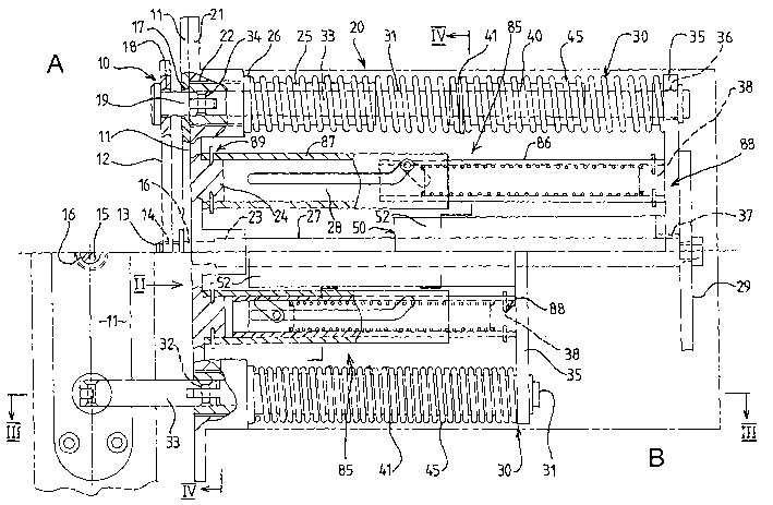
The door closer as illustrated in Figures 1 to 9 comprises an anchor
assembly 10 which is adapted for mounting in a door frame at a vertical edge
thereof facing the hinged edge of a door hingedly carried by the frame, and an
actuator assembly ~20 which is adapted for mounting within the thickness of
the
door.
The anchor assembly 10 comprises a mounting plate 11 and an adjustment
plate 12 which is spaced from the mounting plate on the side thereof remote
from
the door by an adjustable distance. An adjusting screw 13 is engaged in a
threaded hole 14 formed in the adjustment plate 12 and a slotted head portion
15
of the screw bears against the mounting plate 12 and is accessible through a
central hole 16 formed in the mounting plate 11. It will be understood that by
rotation of the screw I3 the spacing of the adjustment plate 12 and mounting
plate 11 can be varied for the purpose hereinafter described.
The mounting plate 11 is also formed with a pair of apertures 17 near the
ends thereof and the adjustment plate 12 is formed with a pair of apertures 18
aligned with the apertures 17 whereby the adjustment plate 12 is coupled to an
operating member 30 of the actuator assembly 20 as hereinafter described.
The actuator assembly 20 is so dimensioned as to be suitable for fitting
within the thickness of the door and for this purpose is provided with a
mounting
member 21 having bosses near the outer ends thereof formed with apertures 22
which align with the apertures 17 of the anchor assembly mounting plate 1 l, a
central boss formed with a bore 23, and intermediate bosses 24.
The apertures 22 locate therein fixed sleeves 25 which are provided with
an external flange 26 abutting against the end face of the boss around
aperture 22.
The central bore 23 is partially threaded to receive a threaded end portion of
a rod
27, and the intermediate bosses 24 each locate one end of a control sleeve 87
(see
CA 02436363 2003-07-25
WO 02/063125 PCT/GB02/00213
9
Figures 6 and 7) by means of screws or pins, as shown. The sleeves 25 and rod
27 extend parallel to one another, there being provided a transverse stop
plate 29
having an intermediate boss 38 which is secured to the free end of the rod 27
by
means of screws or the like, and to one end of a thrust means control member
86,
by screws or pins, as shown in more detail in Figures 6 and 7.
The actuator assembly 20 further includes an operating member 30, as
above-mentioned, which is carried by the mounting member 21 and guided for
longitudinal movement by the sleeves 25 and rod 27. The operating member 30
includes a pair of parallel shafts 31 which are located in the sleeves 2S,
each
having at one end a pivotal connection 32 to a respective rigid link 33 which
is
disposed within the associated sleeve 2S when the closer is in the "door
closed"
condition as shown in Figure 1A. The links 33 have a pivotal connection 34
with
respective headed studs 19 which extend through the apertures 17 in the
mounting plate 11 and through apertures 18 in the adjustment plate 12 of the
anchor assembly 10. The links thus form an articulated connection between the
shafts 31 and the anchor assembly 10.
The operating member 30 further includes, at the other end of the shafts
31, a cross-head 3S by which the shafts 31 are interconnected. The cross-head
3S is formed with outermost bosses with apertures 36 through which the shafts
3I
extend and the cross-head is secured to the shafts 31 by means of pins (not
shown). As seen most clearly in Figure S, the cross-head 3S is also formed
with a
central boss and a central aperture 37 in which the end of the rod 27 is
located
with a sealing ring, and a pair of intermediate bosses 38 to which thrust
means
control members 86 are attached by means of pins or screws.
The operating member 30 is biased inwardly towards the retracted or
"door closed" position shown in Figure 1A under the force of driving springs
4S,
which, in the illustrated embodiment, compromise coil springs extending
between
the cross-head 3S and the flanges 26 on the fixed sleeves 2S. In addition,
floating
sleeves 40 are located on each of the shafts 31 and carry a respective clip 41
CA 02436363 2003-07-25
WO 02/063125 PCT/GB02/00213
which engages between turns of the respective spring 45. Alternatively,
separate
springs may be provided on opposite sides of the clip 41.
As will be evident, the compression springs 45 act on the cross-head 3S to
drive the latter inwardly of the actuator assembly 20 (i.e. to the right of
Figures
1A and 1B) to the retracted position and to draw the shafts 31 and the
associated
links 33 inwardly so as to bring the mounting plate 11 of the anchor assembly
10
up to the mounting member 21 of the actuator assembly, in the manner
illustrated
in Figure 1A, thereby holding the door in its closed position.
When the door is opened, as shown in Figures 1B and 3, the shafts 31 and
cross-head 35 are drawn outwardly (i.e. to the left of Figures 1A and 1B),
thereby
causing the springs 4S to be compressed, abutment of the floating sleeves 40
against the fixed sleeves 2S limiting the outward travel of the cross-head 3S
at an
extended or "door open" position. When the door is released, the coil springs
45
act to return the cross-head 35 and the shafts 31 to their starting positions,
thereby
bringing the door back to its closed position relative to the frame.
The actuator assembly 20 further includes a damper assembly SO to
regulate the rate of closure of the door under the action of the springs 45.
The damper assembly SO as shown in Figure S comprises a fixed piston S1
formed on the rod 27 at an intermediate position, and a cylinder 52 carried by
the
cross-head 3 S and containing hydraulic fluid. The cylinder 52 is located at
one
end, with,an appropriate seal, in a recess S3 formed in a boss at the centre
of the
cross-head 3 S, and is closed at its other end by a plug 54, which is retained
by
means of a clip 55 in the mouth of the cylinder. The plug 54 is formed with a
bore 56 through which the piston rod 27 passes. Appropriate sealing rings 57,
S8
are arranged to engage sealingly with the exterior surface of the rod 27 and
with
the interior surface of the cylinder 52 as shown.
In the illustrated embodiment the fixed piston rod 27 is assembled from
first and second rod sections S9, 60. The first rod section S9 is formed with
a
radial enlargement having a peripheral groove 61 for a sealing ring 62 which
CA 02436363 2003-07-25
WO 02/063125 PCT/GB02/00213
11
engages with the interior face of the cylinder 52 so that the enlargement
serves as
the piston 51. The second rod section 60 includes a widened end portion 63
which has an internal bore 64 to receive an end portion of the first rod
section
59.
The piston 51 divides the cylinder 52 into inner and outer compartments
65, 66 and fluid passageways as hereinafter described are formed in the piston
51
and the rod 27 to enable hydraulic fluid to pass from one compartment of the
cylinder to the other in a controlled manner.
Axial passageways 67 extend directly between opposite faces of the piston
51. The widened end portion 63 of the second rod section 60 has an end face
68 which is spaced axially from the piston 51, and a flexible seal 69 is
disposed
between the end face 68 and the piston 51. The flexible seal 69 is moveable
within the gap between the end face 68 and the piston 51 in response to fluid
pressure so as to close or open the axial passageways 67.
The flexible seal 69, lifts from the ends of the axial passageways 67 in
response to opening movement of the door, so that fluid may flow freely from
the
inner compartment 65 to the outer compartment 66 and the door may be opened
freely. However, in response to movement of the door towards its closed
position
the flexible seal 69 covers the ends of the axial passageways 67 in such a
manner
as to prevent liquid flowing directly from the outer compartment 66 to the
inner
compartment 65 through the axial passageways 67.
To enable fluid to flow from the outer compartment 66 to the inner
compartment 65, radial passageways 70 are formed in the first rod section 59
adjacent to the face of the piston which is presented towards the cross-head
35 to
communicate with a central bore 71 which terminates, at the end of the first
rod
section 59 which is presented towards the mounting member 21, in a throttling
orifice 72. Further radial passageways 73 extend from the outer face of the
widened end portion 63 of the outer rod portion 60 to a central chamber 74
formed at the inner end of an axial bore 75 which extends through the second
CA 02436363 2003-07-25
WO 02/063125 PCT/GB02/00213
12
rod section 60 to its outer end where it is received in the central bore 23 of
the
mounting member 21.
The axial bore 75 includes a widened end portion 76 adjacent to the
central chamber 74, and an internally threaded portion 77 adjacent to the
widened end portion 76. The widened end portion 76 receives an adjustable
throttle member 80 which includes an externally threaded shank portion 81
received within the internally threaded portion 77 of the bore 75, and a
needle
portion 82 which co-operates with the orifice 72. The shank portion 81 of the
throttle member 80 is formed with slot 83 to receive the end of a screwdriver
blade which can be inserted along the bore 75, to enable the throttle member
80
to be rotated to adjust the axial position of the needle portion 82 relative
to the
throttle orifice 72 to provide a variable restriction.
When the passageways 67 are closed by the flexible seal 69,
communication between the two compartments of the cylinder 52 is only
possible through passageways 70, 71 and 73, and the throttling orifice 72. In
this way, the orifice 72 serves as an adjustable throttle to regulate the flow
of
fluid from the outer compartment 66 to the inner compartment 65 as the cross-
head 35 is driven inwardly of the actuator assembly by the compression springs
45. The rate at which the door is closed under the force of the springs 45 can
thus
be adjusted, and it is particularly to be noted that such regulation is
effective
throughout the entire range of movement of the operating member 30 from the
extended position shown in Figure 1B to the retracted position shown in Figure
-- 1A. However, on the reverse stroke, when the door is being opened, the
flexible
seal 69 is able to lift from the ends of the axial passageways 67 and allow
relatively unrestricted flow of fluid between the two compartments.
The actuator assembly 20 further includes a pair of thrust assemblies 85
mounted between the bosses 24 and 3 8, the thrust assemblies being disposed
between the respective driving springs 45 and the damper assembly 50.
CA 02436363 2003-07-25
WO 02/063125 PCT/GB02/00213
13
As shown in Figures 6 and 7, each thrust assembly 85 includes a
hollow cylindrical control member 86 which is slidably received within a
hollow
cylindrical control sleeve 87, the sleeve 87 having a slightly greater
diameter than
that of the control member 86 such that clearance between the outer surface of
the control member 86 and the inner surface of the control sleeve 87 is kept
to a
minimum. This ensures that the control member and sleeve remain generally
concentric, allowing smooth sliding movement to occur between them. As
shown in Figures 1A and 1B, an innermost end portion 88 of the control
member 86 is pinned to the outside of a boss 38, thus securing the control
member thereto, and ensuring that no angular or rotational movement of the
control member 86 is permitted relative to the boss 38. An outermost end
portion 89 of the control sleeve 87 is pinned to the outer surface of boss 24,
the
sleeve 87 thus similarly being prevented from movement relative to the boss
24.
As shown in Figures 7 and 9A the control sleeve 87 is provided with a
pair of similarly configured slots 90, one on each "side" of the sleeve. For
clarity, only one "side" is shown in Figure 7. Each slot 90 has a first,
generally
straight part 91 and a second part 92 extending obliquely away from the first
part 91 at an angle of about 45°. The first part 91 is substantially
parallel with
the longitudinal axis of the control sleeve 87, with the second part 92
extending
away from the first part 91 in generally opposite directions, for the purpose
hereinafter described. Thus, in Figure 7, the part 92 of the "near-side" slot
90
extends upwardly from the longitudinal axis. The corresponding part on the
"far-side" extends downwardly from the= axis. The control member 86 is
provided with a pair of slots 93, the slots 93 extending at an angle of about
45°
to the longitudinal axis of the control member 86, as shown in Figure 9B.
Thrust springs - in the form of compression springs 94 having a rate
greater than that of the main coil springs 45 - are disposed within the
control
members 86, innermost ends of which being secured to a stop 95 which itself is
CA 02436363 2003-07-25
WO 02/063125 PCT/GB02/00213
14
pinned to the inside of the control member 86. The outermost ends of the
thrust
springs 94 are attached to a retaining member 96 which is located towards the
outermost end 97, and which has a circular or part circular cross-section, as
shown especially in Figure 8. The retaining member 96 is provided with a
through-bore (not shown) within which is located a cam follower 98
comprising inner and outer cam rollers 99a and 99b and a retaining pin 100,
about which the cam rollers may each rotate. The cam rollers 99a and 99b axe
maintained in position relative to the retaining pin 100 by a pair of enlarged
portions or fasteners 99c. As the cam follower arrangement 98 is located
within the through-bore provided in the retaining member 96, it will be
appreciated that any movement of the retaining member will effect movement
of the cam follower, and vice versa. As shown in Figure 8, the radius of the
retaining pin 100 is approximately half that of the cam rollers 99a and 99b,
as
such a configuration has been found to minimise the unwanted effects of
friction. It will however be appreciated that other relative radii could
conceivably be adopted, and that just one roller - on the inner or outer race -
could be used. Although it may give rise to increased frictional resistance,
it is
envisaged that' an arrangement having only a pin could be used, the outer
surface of the pin bearing directly on the sides of the slots 90 and 93 .
Referring to Figure 7, which shows . the thrust assembly in a "door
closed" position, it will be seen that the compression spring 94 is not
compressed to any material extent, and no effective force is thus exerted by
the
spring 94 on the retaining member 96. However, as the door moves from a
closed to an open position, as shown in Figure 6, the control member 86 is
pushed further inside the control sleeve 87, walls of the second part of the
slot
in the control sleeve 90 thus acting as a cam surface for the cam follower 98,
causing the cam follower 98, and hence the retaining member 96 and the
compression spring 94 attached thereto, to undergo axial and angular movement
relative to the longitudinal axis of the control member 86.
CA 02436363 2003-07-25
WO 02/063125 PCT/GB02/00213
It will be appreciated that the outermost ends of the thrust springs could
be attached to the retaining members 96 in such a manner as to permit the
springs to rotate relative thereto. Thus, during movement of the door from a
closed to an open position, it is possible that the thrust sp-rings could
undergo
only axial movement, resulting in no torsional deformation.
Movement of the cam follower 98 relative to the control member 86 is
permitted by the pair of slots 93 in the control member 86, with this movement
continuing until the cam follower 98 reaches the junction between the first
and
second parts 91 and 92 of the' control sleeve slots, at which point the first
part
of the control sleeve slot 90 restrains the cam follower 98 against further
angular movement.
It will be appreciated that in view of the fact that the cam follower 98 -
and hence the retaining member 96 - has moved axially in relation to the
control
member 86, by virtue of the angled slot 93 disposed therein, that in addition
to a
torsional force being applied to the thrust spring 94, a compressive force is
also
applied.
Thus, once the cam follower 98 reaches the straight first part 91 of the
control sleeve slot 90, the thrust springs 94 are "primed" in a stressed
"ready"
condition.
During the remainder of the door opening process, the cam follower 98
travels along the remainder of the slot 90, until the cam roller 99 abuts the
distal
end of the slot 90, corresponding to maximum opening of the door. It will be
appreciated that while the cam follower 98 travels along the first part of the
slot
90, the energy stored within the thrust springs 94 remains substantially
constant, as the thrust springs 94 are not permitted to expand or move in any
way, bearing in mind that both ends thereof are held in a fixed position
relative
to each other by the retaining member 96 and the boss 38 which moves with the
cross-head 35.
CA 02436363 2003-07-25
WO 02/063125 PCT/GB02/00213
16
Upon subsequent closure of the door; however, the reverse happens.
Specifically, as the door approaches the point of final closure, the cam
follower
98 - now moving to the right of Figures 6 and 7 - leaves the straight first
part 90
of the control sleeve 87, and re-enters the angled second part 92 thereof. At
this point, the wall of the second part 92 provides the cam follower 98 with a
surface against which a force may be exerted, thus allowing the energy stored
within the thrust spring 94 to be released, the spring 94 thus extending - and
undergoing some angular movement - back towards its "free" state, as shown in
Figure 7.
From this, it will be appreciated that during the initial stage of the door
opening process, and the final stage of the door closing process, an
additional
force is exerted by the thrust spring 94 against the cross-head 35, thus
urging
the cross-head 35 - and hence the operating member 30 - towards a "door
closed" position.
On the other hand, during the "main part" of the door opening and
closing operations (i.e. where the cam follower 98 travels along the straight
part
91 of the control sleeve slot 90), the thrust springs exert no force on the
cross-
head 35 which is effective to resist - or assist - movement of the door.
Thus, the effect of the thrust assembly is to provide an additional closing
force during the final stage of a door closing operation, thus overcoming any
resistance to door closure which may, for example, be imposed by a latching
mechanism which operates between the door and the door frame.
Although a number of materials may be suitable, it is believed that a
hard stainless steel may be particularly advantageous, bearing in mind that
the
relative sliding movement of the control sleeve 87, control member 86, cam
follower 98 and retaining member 96 could well give rise to undesirable wear
problems. It is also envisaged that the mutually engaging services of the
various components could conceivably be coated with a material having an
CA 02436363 2003-07-25
WO 02/063125 PCT/GB02/00213
17
extremely low co-efficient of friction (such as PTFE) to reduce such wear
problems as far as possible.
The adjustment plate 12 enables the point at which the thrust springs 94
come into operation to be varied. Adjustment of the adjustment plate 12
relative
to the mounting plate 11 of the anchor assembly 10 alters the angular position
of
the door at which the cam follower 98 engages the second part 92 of the slot
90,
by varying the spacing between the mounting plate 11 of the anchor assembly 10
and the cross-head 35 of the operating member 30. In this way the fixed
position
of the second parts 92 of the slots 90 corresponds to any selected position of
the
mounting plate 11 within a predetermined range of positions. Typically, the
range of adjustment may be between 0° and about 15° of opening.
Thus at one
extreme, the thrust springs may be rendered ineffective if desired, whilst the
range of angular movement over which they are effective, when required,, can
be
set at up to 15° or thereabouts according to the precise geometry
adopted.
In other words, adjustment of the adjustment plate 12 - and hence
alteration of the spacing between the cross-head 35 and the mounting plate 11 -
alters the starting position of the cam follower 98 in the slot 90. At one
extreme
(shown in Figure 7) compression and torsional deformation of the thrust spring
94 occurs throughout movement of the cam follower 98 from a distal end of the
second part 92 to the junction between the first and second parts 91 and 92 of
the
slot 90. At another extreme, where the cross-head 35 has been adjusted to such
an extent that the cam follower - at a door closed position - is already
located
within the straight first part 91, the thrust springs 94 are maintained
ineffective
against sliding movement of the cross-head 35 throughout the door opening and
closing operations. Thus, at all times during the closing action, the rate of
movement of the door is controlled by the damper assembly 50 but, as
illustrated
in Figure 10, the closing force applied by the driving springs 45 can be
substantially augmented by the thrust springs 94 over a variable final part of
the
CA 02436363 2003-07-25
WO 02/063125 PCT/GB02/00213
18
closure movement, thus overcoming any resistance to closure which may be
imposed by a latching mechanism operating between the door and door frame,
but without the potentially excessive "snap action" associated with previous
door
closers of the kind in which the flow restriction imposed by the damper
assembly
is relieved during the final part of the closure movement. However, adjustment
of the damper makes it possible to provide a controlled degree of snap action,
when the flow restriction is set to a minimum, or a "soft" action, when the
flow
restriction is set to a maximum, or anything in between.
Adjustment of the position of the adjustment plate 12 of the anchor
assembly 10 varies the effective length of the connection between the cross-
head
35 and the anchor assembly, and can thus also enable the action of the thrust
springs 94 to cut in at the correct point despite variations in the width of
the gap
between the inner edge of the door and the door frame in different
installations.
The door closer as above described is fully adjustable with respect to the
selected range of angular movement over which the augmented closure force is
applied, and with respect to the degree of damping applied, whilst being
particularly compact so that it can be installed in a door without
compromising
the f re resistance of the door.
The effect of the thrust springs on the opening and closing forces
generated using a door closer in accordance with the present invention is
shown
graphically in Figure 10 - a graph showing these forces, plotted against a
range
of door/frame angles. Specifically, the graph shows opening and closing forces
relative to degrees of opening of a 750mm wide door at the furthest point from
its .hinge pivot point. From this, it is evident that opening angles of
between
about 3° and about 7 ° produce the greatest opening and closing
forces.
Additionally, it can be seen that the augmentation of the closing force, as
the
door returns towards a closed position, is smooth, in consequence of the
cammed configuration of the control means, which gradually brings the thrust
springs 94 into operation. By movement of the adjustment plate 12, the point
CA 02436363 2003-07-25
WO 02/063125 PCT/GB02/00213
19
(i.e. door angle) at which the thrust springs 94 come into operation can be
varied throughout a range of between 0° and about 15°, so that
the force
profiles shown in Figure 10 may be "shifted" laterally, in that the force
"peaks"
can appear at a range of different opening and closing angles.
The effect of the damper is illustrated in Figure 11 which shows the door
closing speed (V~ plotted against door closing time (T) from the position of
maximum opening to closure, with minimum and maximum damping and an
indication of the variable range of operation of the thrust springs.
With the damping set at minimum, and the action of the thrust springs set
at maximum, the door speed follows the upper solid line curve (IVl7, from
which it
can be seen that at time = to the door accelerates from rest to a uniform
velocity
Vl and at time = tla the thrust springs become effective with the result that
the
door speed increases to a higher velocity V2 until at point A the door reaches
its
position of closure at time = tea .
If the damping is set at the maximum value, the door speed follows the
lower solid line curve (N~ to a lower velocity V3 and the thrust springs
become
effective at time = tlb following which the door speed increases to a value V4
until at point B the door reaches its position of closure at time t = t2b .
However, if the thrust springs are rendered inoperative by appropriate
adjustment of the plate 12, when the damping is set at minimum the door
continues to close at velocity Vl as indicated by the broken line M' until at
point
A' it reaches its position of closure at time t = t1° whereas when the
damping is
set at maximum the door continues at velocity V3 as indicated by broken line
N'
until at point B' it reaches its position of closure at time = t2~ .
The shaded area bounded by points A, A', B and B' represents the
envelope within which the closure time can be varied by the combined
adjustments available by means of the adjustment plate 12 and the adjustable
throttle incorporated in the damper assembly 50.
CA 02436363 2003-07-25
WO 02/063125 PCT/GB02/00213
The features disclosed in the foregoing description, or the following
claims, or the accompanying drawings, expressed in their specific forms or in
terms of a means for performing the disclosed function, or a method or process
for attaining the disclosed result, as appropriate, may, separately, or in any
combination of such features, be utilised for realising the invention in
diverse
forms thereof.