Note : Les descriptions sont présentées dans la langue officielle dans laquelle elles ont été soumises.
CA 02437111 2003-07-30
WO 02/061783 PCT/IB02/00305
CIRCUIT BREAKER
CROSS-REFERENCE TO RELATED APPLICATIONS
This application is related to commonly owned, copending United
States Patent Application Serial No. 09/514,458, filed February 28, 2000,
entitled
"Remotely Controllable Circuit Breaker"; and commonly owned, concurrently
filed
United States Patent Application Serial No. filed
entitled "Circuit Breaker and Panelboard Employing the Same" (Attorney Docket
No.
01-EDP-008).
BACKGROUND OF THE INVENTION
Field of the Invention
This invention relates to circuit breakers for protecting electric power
circuits and, more particularly, to such circuit breakers including separable
contacts,
an operating mechanism and a switch, such as a micro-switch, which follows the
ON,
tripped and OFF states of the operating mechanism.
Background Information
Circuit breakers are used to protect electrical circuitry from damage
due to an overcurrent condition, such as an overload condition or a relatively
high-
level short circuit condition.
Circuit breakers used in residential and light commercial applications
are commonly referred to as miniature circuit breakers because of their
limited size.
Such circuit breakers typically have a pair of separable contacts opened and
closed by
a spring biased operating mechanism. A thermal-magnetic trip device actuates
the
operating mechanism to open the separable contacts in response to persistent
overcurrent conditions and to short circuits.
Circuit breakers typically provide status feedback by a visual
indication only (e.g., by the position of the circuit breaker handle, by an
indication
window).
Some circuit breakers employ a status contact for reporting the status
of the circuit breaker's separable contacts. For example, electri cal
switching devices
may optionally include an auxiliary connection or an auxiliary switch located
therein
to externally indicate the status of the device. Such an auxiliary connection
may
-1 -
CA 02437111 2003-07-30
WO 02/061783 PCT/IB02/00305
include, for example, a connection from an internal auxiliary switch to a bell
alarm
and/or other external circuits for enunciating and/or monitoring the
open/closed/tripped status of the electrical switching device.
U.S. Patent Nos. 5,301,083 and 5,373,411 describe a remotely operated
circuit breaker, which introduces a second pair of switching relay contacts in
series
with the main separable contacts. The main contacts still interrupt the
overcurrent,
while the secondary contacts perform the discretionary switching operations
(e.g.,
load shedding). The secondary contacts are opened by a solenoid, which is
spring
biased to close the contacts. Feedback circuitry, including normally open and
normally closed auxiliary feedback contacts, provides a status indication of
the
condition of the secondary contacts.
Known circuit breakers of such types only provide the status of the
switching contacts. There is a need, therefore, to also provide the status of
the main
contacts.
Typically, there are significant space limitations in relatively small,
miniature circuit breakers. Adding micro-switches to small circuit breakers
has been
found to be difficult because such breakers typically have limited space due
to their
configuration for mounting in a standardized load center or panelboard. U.S.
Patent
No. 5,552,755 discloses an example of a small residential or light industrial
or
commercial circuit breaker, which is provided with a micro-switch to generate
an
electrical indication that the circuit breaker contacts are opened. Two
cascaded
actuating members, one actuated by the handle structure and one by the cradle,
are
incorporated into the circuit breaker for actuating a plunger of the micro-
switch and
indicating the operating status of the breaker.
U.S. Patent No. 5,907,461 discloses a circuit breaker including a bell
switch and an auxiliary switch positioned in the circuit breaker housing for
actuation
by levers mounted on a cradle pin and crossbar, respectively.
U.S. Patent No. 6,040,746 discloses micro-switches mounted in a
compartment and molded housing of a circuit breaker separate from the
compartment
in which the circuit breaker mechanism is mounted. The micro-switches are
actuated
to indicate the operating status of the circuit breaker by cascaded first and
second
actuating members. The first actuating member bears, against a cam surface on
the
-2 -
CA 02437111 2003-07-30
WO 02/061783 PCT/IB02/00305
operating handle of the circuit breaker. The cam surface actuates the micro-
switches
through the first actuating member when the operating handle is in the OFF
position.
The second actuating member engages a cradle of the circuit breaker and
actuates the
micro-switches through the first actuating member when the cradle is unlatched
(i.e.,
tripped).
U.S. Patent No. 6,104,265 discloses a miniature circuit breaker
including side-by-side ganged cases. One of the ganged cases includes the main
circuit breaker operating mechanism and contacts and the other ganged case
includes
an actuable micro-switch having a switch bar. A handle tie arrangement
interconnects
one circuit breaker handle with a similar handle in the parallel cell of the
circuit
breaker arrangement. If the circuit breaker mechanism of the active cell is
opened, a
common tie-in member causes the handle and, thus, a peninsula portion of the
handle
to move toward the switch bar and cause it to actuate the switch and provide
an
external indication that the circuit breaker has opened. However, a different
mechanism actuates the switch when the circuit breaker is tripped. A rotatable
axial
shaft extending from the adjacent chamber includes an electrically insulating
triggering device having an elongated cam member, which rotates toward the
switch
bar and causes it to actuate the switch.
There is room for improvement in circuit breakers including a switch
which follows the ON, tripped and OFF states of the operating mechanism.
SUMMARY OF THE INVENTION
This need and others are satisfied by the invention, which is directed to
a circuit breaker, which includes a switch that provides the status of the
circuit
breaker's separable contacts (i.e., ON, tripped, OFF). A switching mechanism,
such
as a micro-switch, is provided internal to the circuit breaker housing and is
actuated
by the operator handle or movable contact arm of the operating mechanism. The
contact of the switch, in turn, is wired in a variety of fashions. As one
example, the
switch contact is used in conjunction with a remote controlled circuit breaker
in order
to provide feedback of both the main separable contacts as well as the relay
switching
contacts.
As one aspect of the invention, a circuit breaker comprises: a housing;
at least one set of separable contacts including a set of main contacts; an
operating
-3 -
CA 02437111 2003-07-30
WO 02/061783 PCT/IB02/00305
mechanism including an operator handle for opening and closing the separable
contacts, the operator handle having a surface, an ON position, a tripped
position, and
an OFF position, the separable contacts being closed in the ON position, being
open
in the tripped position, and being open in the OFF position; a trip mechanism
releasing the operating mechanism to move the operator handle to the tripped
position; and a switch including an actuator lever movable between an actuated
position and a non-actuated position and adapted to engage the surface of the
operator
handle of the operating mechanism, the switch also including a contact having
a first
state corresponding to the actuated position and a second state corresponding
to the
non-actuated position, the surface of the operator handle engaging and moving
the
actuator lever to the actuated position in only the ON position of the
operator handle,
the actuator lever being in the non-actuated position in the OFF position and
the
tripped position of the operator handle.
According to a preferred practice, the housing includes a base portion
and a cover portion; and the switch is a micro-switch having a first side,
which
engages the base portion, and an opposite second side, which engages the cover
portion.
As another preferred practice, the at least one set of separable contacts
is the set of main contacts; and the contact of the switch has an input
adapted to
receive a voltage and an output adapted to provide a feedback voltage external
to the
housing when the set of separable contacts is closed.
As another aspect of the invention, a circuit breaker comprises:
separable contacts; an operating mechanism including a movable contact arm for
opening and closing the separable contacts, the movable contact arm having a
surface,
an ON position, a tripped position, and an OFF position, the separable
contacts being
closed in the ON position, being open in the tripped position, and being open
in the
OFF position; a trip mechanism releasing the operating mechanism to move the
movable contact arm to the tripped position; and a switch including an
actuator lever
movable between an actuated position and a non-actuated position and adapted
to
engage the surface of the movable contact arm of the operating mechanism, the
switch
also including a contact having a first state corresponding to the actuated
position and
a second state corresponding to the non-actuated position, the surface of the
movable
-4 -
CA 02437111 2003-07-30
WO 02/061783 PCT/IB02/00305
contact arm engaging and moving the actuator lever to the actuated position in
the
tripped position and the OFF position of the movable contact arm, the actuator
lever
being in the non-actuated position in the ON position of the movable contact
arm.
As a further aspect of the invention, a circuit breaker comprises: a
molded housing having a base portion and a cover portion; separable contacts;
an
operating mechanism including an operator handle for opening and closing the
separable contacts, the operator handle having a surface, an ON position, a
tripped
position, and an OFF position, the separable contacts being closed in the ON
position,
being open in the tripped position, and being open in the OFF position; a trip
mechanism releasing the operating mechanism to move the operator handle to the
tripped position; and a micro-switch including an actuator lever movable
between an
actuated position and a non-actuated position and adapted to engage the
surface of the
operator handle of the operating mechanism, the switch also including a
contact
having a first state corresponding to the actuated position and a second state
corresponding to the non-actuated position, the surface of the operator handle
engaging and moving the actuator lever to the actuated position in the ON
position of
the operator handle, the actuator lever being in the non-actuated position in
the OFF
position and the tripped position of the operator handle, the micro-switch
having a
first side, which engages the base portion of the molded housing, and an
opposite
second side, which engages the cover portion of the molded housing.
As one preferred practice, the base portion and the cover portion of the
molded housing define a compartment, which houses the separable contacts, the
operating mechanism, the trip mechanism and the micro-switch.
As another aspect of the invention, a circuit breaker comprises:
separable contacts; an operating mechanism including an operator handle for
opening
and closing the separable contacts, the operator handle having a surface, an
ON
position, a tripped position, and an OFF position, the separable contacts
being closed
in the ON position, being open in the tripped position, and being open in the
OFF
position; a trip mechanism releasing the operating mechanism to move the
operator
handle to the tripped position; a micro-switch including a first side, an
opposite
second side, and an actuator lever movable between an actuated position and a
non-
actuated position and adapted to be actuated by the surface of the operator
handle of
-5 -
CA 02437111 2003-07-30
WO 02/061783 PCT/IB02/00305
the operating mechanism, the switch also including a contact having a first
state
corresponding to the actuated position and a second state corresponding to the
non-
actuated position, the contact having one of the first and second states in
the ON
position of the operator handle, and having the other of the first and second
states in
the OFF position and the tripped position of the operator handle; and a molded
housing having a base portion, which engages the first side of the micro-
switch, and a
cover portion, which engages the second side of the micro-switch, the base
portion
and the cover portion of the molded housing defining a compartment, which
houses
the separable contacts, the operating mechanism, the trip mechanism and the
micro-
switch.
BRIEF DESCRIPTION OF THE DRAWINGS
A full understanding of the invention can be gained from the following
description of the preferred embodiments when read in conjunction with the
accompanying drawings in which:
Figure 1 is an elevational view of a remotely controllable circuit
breaker shown with the cover removed and with the main contacts and secondary
contacts closed.
Figure 2 is a view similar to that of Figure 1 with the secondary
contacts open.
Figure 3 is an elevational view of a remotely controllable circuit
breaker in accordance with an embodiment of the invention in which the
operator
handle actuates the actuator lever of a micro-switch in the handle ON
position.
Figure 4 is a view similar to that of Figure 3 with the operator handle
disengaged from the actuator lever of the micro-switch in the handle OFF
position.
Figure 5 is a view similar to that of Figure 3 with the operator handle
in the handle tripped position and not actuating the actuator lever of the
micro-switch.
Figure 6 is a schematic circuit diagram of a control and monitoring
circuit for the remotely controllable circuit breaker of Figure 3.
Figure 7 is a schematic circuit diagram of another control and
monitoring circuit for a remotely controllable circuit breaker in accordance
with
another embodiment of the invention.
-6 -
CA 02437111 2003-07-30
WO 02/061783 PCT/IB02/00305
Figure 8 is a schematic circuit diagram of a monitoring circuit for a
circuit breaker in accordance with another embodiment of the invention.
Figure 9 is a schematic circuit diagram of another control and
monitoring circuit for the remotely controllable circuit breaker of Figure 3.
Figure 10 is an elevational view of a remotely controllable circuit
breaker in accordance with another embodiment of the invention in which the
movable contact arm does not actuate the actuator lever of a micro-switch in
the ON
position.
Figure 11 is a view similar to that of Figure 10 with the movable
contact arm actuating the actuator lever of the micro-switch in the OFF
position.
Figure 12 is a view similar to that of Figure 10 with the movable
contact arm actuating the actuator lever of the micro-switch in the tripped
position.
DESCRIPTION OF THE PREFERRED EMBODIMENTS
The invention will be described as applied to a miniature circuit
breaker, although it will become apparent that it could be applied to other
types of
circuit breakers as well.
Figures 1 and 2 show a miniature circuit breaker 1 including a molded
housing 3 having a base portion 4 with the cover portion (not shown) of the
housing
removed. The basic components of the circuit breaker 1 are a set of main
contacts 5,
an operating mechanism 7 for opening the set of main contacts 5, and a thermal-
magnetic trip device 9 which actuates the operating mechanism to trip the set
of main
contacts 5 open in response to certain overcurrent conditions. Further
included are a
set of secondary contacts 11 and an actuator, such as a magnetically latchable
solenoid 13, which is remotely controllable to control the open and closed
states of
the set of secondary contacts 11.
The set of main contacts 5 includes a fixed contact 15 secured to a line
terminal 17 and a moveable main contact 19 which is affixed to an arcuate
contact
arm 21 which forms part of the operating mechanism 7. The operating mechanism
7
is a well-known device, which includes a pivotally mounted operator 23 with an
integrally molded handle 25. The operating mechanism also includes a cradle 27
pivotally mounted on a support 29 molded in the housing. With the handle 25 in
the
ON position, as shown in Figures 1 and 2, a spring 31 connected to a hook 33
on the
-7 -
CA 02437111 2003-07-30
WO 02/061783 PCT/IB02/00305
contact arm 21 and a tab 35 on the cradle 27 holds the main contacts 5 closed.
The
spring 31 also applies a force with the set of main contacts 5 closed, as
shown, to the
cradle 27 which tends to rotate the cradle in a clockwise direction about the
support
29. However, the cradle 27 has a finger 37, which is engaged by the thermal-
magnetic trip device 9 to prevent this clockwise rotation of the cradle under
normal
operating conditions.
The thermal-magnetic trip device 9 includes an elongated bimetal 39
which is fixed at its upper end to a tab 41 on the metal frame 42 seated in
the molded
housing 3. Attached to the lower, free end of the bimetal 39 by a lead spring
43 is an
armature 45. The armature 45 has an opening 47, which is engaged by a latching
surface 49 on the finger 37.
The free end of the bimetal 39 is connected to the contact arm 21 by a
flexible braided conductor 51 so that the load current of the circuit
protected by the
circuit breaker 1 passes through the bimetal. A persistent overcurrent heats
the
bimetal 39, which causes the lower end to move to the right with respect to
Figures 1
and 2. If this overcurrent is of sufficient magnitude and duration, the
latching surface
49 on the finger 37 is pulled out of engagement with the armature 45. This
allows the
cradle 27 to be rotated clockwise by the spring 31. The clockwise rotation of
the
cradle 27 moves the upper pivot point for the contact arm 21 across the line
of force
of the spring 31 so that the contact arm is rotated counter-clockwise, to open
(not
shown) the set of main contacts 5, as is well understood. This also results in
the
handle 25 rotating to an intermediate position (not shown) to indicate the
tripped
condition of the set of main contacts 5.
In addition to the armature 45, a magnetic pole piece 53 is supported
by the bimetal 39. Very high overcurrents, such as those associated with a
short
circuit, produce a magnetic field which draws the armature 45 to the pole
piece 53,
thereby also releasing the cradle 27 and tripping the set of main contacts 5
open.
Following either trip, the main set of contacts 5 are reclosed by moving the
handle 25
fully clockwise, which rotates the cradle 27 counter-clockwise until the
finger 37
relatches in the opening 47 in the armature 45. Upon release of the handle 25,
it
moves counter-clockwise slightly from the full clockwise position and remains
there.
With the cradle relatched, the line of force of the spring 31 is reestablished
to rotate
-8 -
CA 02437111 2003-07-30
WO 02/061783 PCT/IB02/00305
the contact arm 21 clockwise to close the set of main contacts 5 when the
handle 25 is
rotated fully counter-clockwise to the position shown in Figures 1 and 2.
The set of secondary contacts 11 includes a fixed secondary contact 55
which is secured on a load conductor 57 which leads to a load terminal 59. The
set of
secondary contacts 11 also includes a moveable secondary contact 61 which is
fixed
to a secondary contact arm 63 which at its opposite end is seated in a molded
pocket
65 in the molded housing 3. The secondary contact arm 63 is electrically
connected
in series with the set of main contacts 5 by a second flexible braided
conductor 67
connected to the fixed end of the bimetal 39. Thus, a circuit or load current
is
established from the line terminal 17 through the set of main contacts 5, the
contact
arm 21, the flexible braided conductor 51, the bimetal 39, the second flexible
braided
conductor 67, the secondary contact arm 63, the set of secondary contacts 11,
and the
load conductor 57 to the load terminal 59.
The set of secondary contacts 11 is biased to the closed state shown in
Figure 1 by a helical compression spring 69 seated on a projection 71 on an
offset 73
in the secondary contact arm 63. As discussed in U.S. Patent No. 5,301,083,
the
spring 69 is oriented such that the force that it applies to the secondary
contact arm 63
tending to close the set of secondary contacts 11 is relaxed to a degree with
the
secondary contacts in the open position. This serves the dual purpose of
providing the
force needed to close the secondary contacts against rated current in the
protected
circuit and also reducing the force that must be generated by the magnetically
latching
solenoid 13 to hold the secondary contacts in the open state. In order for the
set of
secondary contacts 11 to withstand short circuit currents and allow the set of
main
contacts 5 to perform the interruption, the magnet force generated by the
short circuit
current causes an armature 75 mounted on the secondary contact arm 63 to be
attracted to a pole piece 77 seated in the molded housing 3 thereby clamping
the
secondary contacts closed.
As shown by the partial sections in Figures 1 and 2, the
actuator/solenoid 13 includes a first or close coil 79 and a second or open
coil 81
concentrically wound on a steel core 83 supported by a steel frame 85. A
plunger 87
moves rectilinearly within the coils 79 and 81. A permanent magnet 89 is
seated
between the steel core 83 and the steel frame 85.
-9 -
CA 02437111 2009-12-18
WO 02/061783 PCT/IB02/00305
The plunger 87 engages the secondary contact arm 63. When the close
coil 79 is energized, a magnetic field is produced which drives the plunger
downward
to a fast position which rotates the secondary contact arm 63 clockwise and
thereby
moves the set of secondary contacts 11 to the closed state. The secondary
contacts 11
are maintained in the closed state by the spring 69. When it is desired to
open the set
of secondary contacts 11, the open coil 81 is energized which lifts the
plunger 87 and
with it the secondary contact arm 63 to a second position which opens the set
of
secondary contacts 11. With the plunger 87 in the full upward position as
shown in
Figure 2, it contacts the steel core 83 and is retained in this second
position by the
permanent magnet 89. Subsequently, when the close coil 79 is energized, the
magnetic field generated is stronger than the field generated by the permanent
magnet
and therefore overrides the latter and moves the plunger 87 back to the first,
or closed
position.
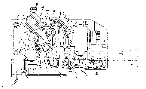
Figures 3-5 show a remotely controllable circuit breaker 90 in
accordance with the present invention. The circuit breaker 90 is similar to
the circuit
breaker I of Figures 1 and 2, except that it includes the pivotally mounted
operator
handle 91 (Figures 3-5), a switch such as the exemplary micro-switch 92
(Figures 3-
6), molded housing 93 (Figures 3-5), and control and monitoring circuit 94 (as
best
shown in Figure 6). The operator handle 91 has a surface 95, an ON position
(shown
in Figure 3), an OFF position (Figure 4), and a tripped position (Figure 5).
As is well
known, the main separable contacts 5 are closed in the ON position of Figure
3, and
are open in the OFF and tripped positions, and the operator handle 91 is
employed to
open and close the separable contacts 5. As discussed in connection with
Figures 1-2,
the thermal-magnetic trip device 9 and/or the magnetic pole piece 53 release
the
operating mechanism 96 of Figure 3 and the operator handle 91 to the tripped
position
as shown in Figure 5.
The micro-switch 92 includes an actuator lever 97 movable between an
actuated position (Figure 3) and a non-actuated position (Figures 4 and 5).
The
actuator lever 97 is adapted to engage the surface 95 of the operator handle
91 as
shown in Figure 3. The micro-switch 92 includes a normally open contact 98
(Figure
6), which is closed in the actuated position of the micro-switch and is
otherwise open
in the non-actuated position. The surface 95 of the operator handle 91 engages
and
-10 -
CA 02437111 2003-07-30
WO 02/061783 PCT/IB02/00305
moves the actuator lever 97 to the actuated position in only the ON position
(Figure 3)
of the operator handle. Otherwise, the actuator lever 97 is in the non-
actuated
position in the OFF position (Figure 4) and the tripped position (Figure 5) of
the
operator handle 91. The exemplary micro-switch 92 also includes a normally
closed
contact (not shown), although the invention is applicable to any suitable
switch
having a single normally open or closed contact.
As shown in Figure 5, in the handle tripped position, the actuator lever
97 has pivoted counter-clockwise about pivot point 97A to at or past its non-
actuated
position. In the exemplary embodiment, the operator handle 91 continues to
engage
the actuator lever 97, which remains in the non-actuated position, in the
tripped
position of the operator handle. As shown in Figure 4, the operator handle 91
is
disengaged from the actuator lever 97 in the handle OFF position. The
invention,
however, is not limited by the exemplary embodiment and is applicable to any
operator handle in which an operator handle surface engages and moves a switch
actuator lever to its actuated position in only the ON position of such
operator handle,
with such actuator lever being in its non-actuated position in the OFF
position and the
tripped position of the operator handle.
Figure 6 shows a schematic circuit diagram of the control and
monitoring circuit 94 for the circuit breaker 90 of Figures 3-5. The circuit
94 is
similar to a circuit 94' employed by the circuit breaker 1 of Figure 1, except
that the
normally open contact 98 of the micro-switch 92 is employed in the feedback
monitoring function as discussed below. The first and second or close and open
coils
79,81 of the magnetically latching solenoid 13 are remotely controlled by the
circuit
94. This circuit 94 includes a switch or internal power cutoff device in the
form of
micro-switch 99, which has a common terminal 101 and first and second switched
terminals 103,105. The micro-switch 99 includes a first contact 107 connected
between the common terminal 101 and the first switched terminal 103, and a
second
contact 109 connected between the common terminal 101 and the second switched
terminal 105. In the form of the circuit shown, the first contact 107 of the
micro-
switch 99 is a normally open contact and the second contact 109 is a normally
closed
contact. The common terminal 101 of the micro-switch 99 is connected to a
remotely
located voltage source 111 through a lead 113. The first or close coil 79 of
the
-11 -
CA 02437111 2003-07-30
WO 02/061783 PCT/IB02/00305
solenoid 13 is connected between the first switched terminal 103 of the micro-
switch
99 and a remotely located second or close switch 115 through diode 127A and
through a lead 117. The other side of the close switch 115 is connected to
ground.
Similarly, the second or open coil 81 is connected between the second switched
terminal 105 of the micro-switch 99 and a third or open switch 119 through
diode
127B and through lead 121. Again, the other side of the switch 119 is
grounded.
The micro-switch 99 has an operating member in the form of actuator
lever 123, which is engaged by a projection 125 on the plunger 87 of the
solenoid 13.
When the solenoid 13 is latched is in the upward or second position (as shown
in
Figure 6) so that the second set of contacts 11 is open, the micro-switch 99
is actuated
and the first or normally open contact 107 is closed while the normally closed
contact
109 is open. Thus, the voltage source 111 is connected to enable the close
coil 79 so
that whenever the remote close switch 115 is closed, the coil 79 will be
energized. A
rectifier circuit is implemented by exemplary diodes 127A,127B from terminals
103,105, respectively. In this manner, only voltage of the proper polarity can
energize the coil 79 to effect downward movement of the plunger 87. Also, with
the
diodes 127A,127B, an AC voltage as well as a DC voltage can be used for the
voltage
source 111. The diodes 127A, 127B will provide half wave rectification of any
AC
signal. Since the solenoid 13 latches in the open and closed positions, only
momentary power is needed to open and close the set of secondary contacts 11.
This
momentary power can be provided by an AC source, a DC source or a pulse
source.
Alternatively, in place of the diodes 127A,127B, a suitably polarized diode
(not
shown) having its cathode electrically connected to the terminal 101 can be
provided
in the lead 113.
When the close coil 79 is energized, the plunger 87 is driven
downward to its first position which closes the set of secondary contacts 11
and
allows the actuator lever 123 of the micro-switch 99 to move to the closed
position
123' shown in phantom in Figure 6. This results in closure of the normally
closed
contact 109 and opening of the normally open contact 107. The set of secondary
contacts 11 remains latched in the closed position due to the spring 69. With
the
normally closed contact 109 now closed, the open coil 81 is enabled by
application of
the voltage from the voltage source 111. However, no current flows through the
open
-12 -
CA 02437111 2003-07-30
WO 02/061783 PCT/IB02/00305
coil 81 until the remote open switch 119 is closed to complete the circuit for
the open
coil.
In accordance with the present invention, the normally closed contact
109, which is closed when the secondary contacts 11 are closed, is
electrically
connected in series with the normally open contact 98 of the first micro-
switch 92.
That normally open contact 98 is closed when the actuator lever 97 is actuated
and the
set of main contacts 5 is closed. In order to provide an indication of the
status of both
the main contacts 5 and the secondary contacts 11, a status line 129 is
electrically
connected to one terminal 130 (NO) of the micro-switch 92 and the other
terminal 131
(C) is electrically connected to the second switched terminal 105 of the micro-
switch
99. With both sets of the contacts 5,11 being closed, the normally open
contact 92
and the normally closed contact 109 are closed. The status line 129 therefore
provides a voltage signal from voltage source 111 relative to ground at status
terminals 132, which is indicative of the closed state of both sets of the
contacts 5,11.
That voltage signal is not present at the terminals 132 in the event that
either or both
of the contacts 5,11 are open, including the case when the contacts 5 are
tripped open.
As the set of secondary contacts 11 is latched in either the open state or
the closed state, it is not necessary to provide continuous power from the
voltage
source 111 to maintain them in either state. Accordingly, momentary signals
can be
used to control operation of the solenoid 13. The remote close and open
switches 115
and 119 can be manual switches or automatic switches, such as output contacts
of a
computer system. Similarly, the status terminals 132 can be input terminals on
such a
computer-controlled system.
Although a voltage signal is provided relative to ground at status
terminals 132 when both sets of the contacts 5,11 are closed, the feedback
logic may
be reversed by employing the normally open contact 107 of the micro-switch 99
in
series with the normally closed (NC) contact of the micro-switch 92, such that
a
voltage signal is provided relative to ground at status terminals 132 when
both sets of
the contacts 5,11 are open.
Referring again to Figure 4, the molded housing 93 includes a base
portion 134 and a cover portion 136 (shown cut-away for convenience of
reference).
The base portion 134 includes a first surface 138, which engages a lower side
of the
-13 -
CA 02437111 2003-07-30
WO 02/061783 PCT/IB02/00305
micro-switch 92, and a second surface 140, which is normal to the first
surface 138.
The upper side 142 of the micro-switch 92 engages a surface 144 (shown in
phantom
line drawing) of the cover portion 136. A side 146 of the micro-switch 92,
which is
normal to its lower and upper sides, engages the surface 140 of the base
portion 134.
The micro-switch 92 has an opening 148 extending from the lower side to the
upper
side thereof. A pin 150 engages the micro-switch 92 within the opening 148 and
engages the base portion 134 within an opening 151 (Figure 5) thereof. In this
manner, the micro-switch 92 is suitably and compactly securing within the
housing 93
by the surfaces 13 8,140,144 and the pin 150. Alternatively, two pins (not
shown)
may be employed, or one or two protrusions (not shown) may be provided from
the
base portion 134.
In accordance with a preferred practice of the invention, the base and
cover portions 134,136 of the molded housing 93 define a single compartment
152,
which houses the separable contacts 5, the operating mechanism 96, the trip
mechanism formed by the exemplary thermal-magnetic trip device 9 and the
magnetic
pole piece 53, and the micro-switch 92.
Figure 7 shows a remotely controllable circuit breaker 160, which is
similar to the circuit breaker 90 of Figures 3-5, except that a different
feedback circuit
162 is employed. The circuit 162 includes a first lead 164, which is
electrically
connected to the (NO) terminal 130 of the micro-switch 92, and a second lead
166,
which is electrically connected to the (NC) terminal 105 of the micro-switch
99.
Also, the lead 113 providing the input voltage from a voltage source (not
shown) is
electrically connected to the common terminals 101,131 of both of the
respective
micro-switches 99,92. The normally open (NO) contact 98 of the micro-switch
92,
thus, provides a feedback voltage on lead 164 when the main contacts 5 are
closed.
The feedback voltage is, however, not present whenever those contacts are open
or
tripped open. In a similar manner, the normally closed (NC) contact of the
micro-
switch 99 provides a feedback voltage on lead 166 when the secondary contacts
11
are closed. That feedback voltage is, however, not present whenever those
contacts
are open.
Figure 8 shows a circuit breaker 170, which is a simplified form of the
circuit breaker 90 of Figures 3-5, in that the secondary contacts 11 and the
control and
-14 -
CA 02437111 2003-07-30
WO 02/061783 PCT/IB02/00305
monitoring circuit 94 are removed, and the main contacts 5 and elongated
bimetal 39
are electrically connected in series between the line terminal 17 and the load
terminal
59. Otherwise, the circuit breaker 170 includes the operating mechanism 96,
the
operator handle 91, and the micro-switch 92 of Figures 3-5 in combination with
a
different feedback circuit 172. The normally open contact of the micro-switch
92 has
the terminal 131 adapted to receive a voltage from lead 174 and also has the
terminal
130 adapted to provide a feedback voltage on lead 176 when the separable
contacts 5
are closed. Alternatively, the feedback logic may be reversed by employing a
normally closed (NC) contact (not shown), such that a voltage signal is
provided on
lead 176 when the separable contacts 5 are open.
Figure 9 shows another control and monitoring circuit 180 for the
remotely controllable circuit breaker 90 of Figures 3-5. The circuit 180 is
different
from the circuit 94 of Figure 6 in that a different monitoring function is
provided. In
this embodiment, the normally closed contact 109 of the micro-switch 99, which
contact is closed when the secondary contacts 11 are closed, is electrically
connected
in series with the normally open contact 98 of the micro-switch 92, which
contact is
closed when the main contacts 5 are closed. The lead 113 from the voltage
source
111 is electrically connected to a node 181 defined by the common terminals
101,131
of the two micro-switches 99,92. A first circuit element, which in the
exemplary
embodiment is a first resistor 182, is electrically connected between the
normally
open contact 98 and node 185 at the status line 129, and a second circuit
element,
which in the exemplary embodiment is a second resistor 184, is electrically
connected
between the normally closed contact 109 of the micro-switch 99 and the node
185.
According to one practice, the resistor 182 has a first resistance value
(e.g., 2 KS2) and
the resistor 184 has a different second resistance value (e.g., 4 KQ). In this
manner,
four unique status signals maybe provided at the status terminals 132 based
upon the
four possible states of the separable contacts 5,11 (e.g., OFF/OFF, OFF/ON,
ON/OFF,
and ON/ON). Alternatively, the resistors 182,184 may be replaced by diodes
(not
shown) having their cathodes or anodes electrically connected to the node 185,
whenever the voltage source 111 is an AC source.
Figures 10-12 show a remotely controllable circuit breaker 190, which
is similar to the circuit breaker 90 of Figures 3-5, except that a micro-
switch 192 has a
-15 -
CA 02437111 2003-07-30
WO 02/061783 PCT/IB02/00305
different actuator lever 194 and is mounted in an inverted position with
respect to the
base portion 134 of the molded housing 93. Figures 10, 11 and 12 respectively
show
the circuit breaker movable contact arm 21 of the operating mechanism 96 in
the ON
position, the OFF position and the tripped position. The actuator lever 194 is
movable
between an actuated position (Figures 11 and 12) and a non-actuated position
(Figure
10) and is adapted to engage the movable contact arm 21.
As shown in Figure 10, the movable contact arm 21 engages, but does
not actuate, the actuator lever 194 in the ON position. A surface 198 of the
movable
contact arm 21 engages and moves the actuator lever 194 to the actuated
position in
the tripped position (Figure 12) and the OFF position (Figure 11) of the arm
21.
Otherwise, the actuator lever 194 is in the non-actuated position in the ON
position of
the arm 21. The normally closed (NC) contact of the micro-switch 192 has an
open
state corresponding to the actuated position (tripped and OFF positions) and a
closed
state corresponding to the non-actuated position (ON position). Hence, it will
be
appreciated that the normally closed (NC) contact of the micro-switch 192 may
provide a similar functionality as the normally open (NO) contact 98 of the
micro-
switch 92 of Figures 3-9.
Preferably, since the movable contact arm 21 is energized in the ON
position of the circuit breaker 190, the actuator lever 194 includes an
insulator 200
such that the energized surface 198 of the arm 21 engages the insulator 200,
but does
not energize the actuator lever 194.
As shown in Figure 11, in the handle OFF position, the actuator lever
194 has pivoted about pivot point 196 counter-clockwise at least to its
actuated
position. As shown in Figure 12, some additional counter-clockwise rotation of
the
actuator lever 194 is possible in the tripped position of the movable contact
arm 21.
Although the surface 198 of the arm 21 engages the insulator 200 in the ON
position
of Figure 10, the invention, however, is not limited by the exemplary
embodiment and
is applicable to any movable contact arm which engages and moves an actuator
lever
to an actuated position in the tripped position and the OFF position of such
arm, with
such actuator lever being in a non-actuated position in the ON position of
such arm.
The exemplary switching mechanisms 92,192 actuate off of the
operator handle 91 (Figures 3-5) or movable contact arm 21 (Figures 10-12). In
the
-16 -
CA 02437111 2003-07-30
WO 02/061783 PCT/IB02/00305
former embodiment, the switching mechanism is a micro-switch 92 having a
normally
open contact 98, which contact closes when the operator handle 91 is moved to
the
ON position to actuate the switch. In the latter embodiment, the switching
mechanism is a micro-switch 192 having a normally closed contact, which
contact
opens when the movable contact arm 21 is moved to the OFF or tripped positions
to
actuate the switch. This change of state results in a dry contact closing
and/or
opening. In these examples, the micro-switches operate as a single pole,
double throw
switch. The closing and/or opening thereof may then be advantageously employed
by
a user as a feedback of the circuit breaker's position, thereby telling the
user of the
circuit breaker's status.
These exemplary switching mechanisms are advantageous in
conventional thermal magnetic circuit breakers having one set of separable
contacts,
as well as in remote controlled circuit breakers having an additional set of
relay
switching contacts in series with the main contacts. In this manner, the user
is able to
distinguish between a remote operation that opens or closes the relay
switching
contacts from the opening or closing of the main contacts.
While specific embodiments of the invention have been described in
detail, it will be appreciated by those skilled in the art that various
modifications and
alternatives to those details could be developed in light of the overall
teachings of the
disclosure. Accordingly, the particular arrangements disclosed are meant to be
illustrative only and not limiting as to the scope of invention which is to be
given the
full breadth of the claims appended and any and all equivalents thereof.
-17 -