Note : Les descriptions sont présentées dans la langue officielle dans laquelle elles ont été soumises.
CA 02437465 2003-08-05
WO 02/063582 PCT/US02/02947
CONTROL SYSTEM WITH CAPACITIVE DETECTOR
The present invention is generally related to automatic
control systems and is more particularly directed to a system
for controlling operation of a device utilizing a capacitive
sensor.
A great number of capacitive sensors have been
heretofore developed for the sensing of persons or materials
to provide an alarm, indicating signal, or control. For
example, capacitive sensing circuits have been used for alarm
systems to provide a signal in response to touching of a
particular area or the proximity of an object. In other
instances, capacitive sensing circuits have been utilized to
detect the presence or absence of liquids and solids and
thereafter initiating an indicator for alarm signals or
measurement. Capacitive sensors have also been used to
measure the distance to an object, material size, material
moisture content, oil contamination, humidity, pressure,
liquid level and in fact have formed the basis for sensing in
numerous measurement and detection applications.
With regard to dispenser control, it is often preferable
to operate a device without direct handling thereof by human
interaction. For example, it is preferable for sanitary
reasons in washing to avoid the need for physical contact
with faucet handles, towel dispensers, hand dryers, soap
dispensers and the like.
While a number of control systems have been developed
for such touch-free devices in order to conserve water and
soap, they have been plagued by false activation. That is,
devices are turned on without the actual presence of a human
1
CA 02437465 2003-08-05
WO 02/063582 PCT/US02/02947
body part. This, of course, leads to fluid waste that is
contrary to the original purpose of the control system.
Further, in the case of soap dispensers and the like,
safety becomes a factor when such liquids are falsely
dispensed and accumulate on a floor, or other surface, where
subsequent slippage thereon may cause bodily harm.
The problem of false activation, and more generally of
reliable as well as sensitive detection of a proximate obj ect
by a proximity sensor, stems from the need to reliably
discriminate between a small change in signal strength due to
changes in the proximity of the object versus changes in
signal strength which can occur due to other factors such as
sensor noise, sensor drift or induced changes in the signal
due to actual changes in the ambient environment itself, such
as contamination of the sensor and other effects which can
give rise to signals which are similar in magnitude to or
even larger than the detection signal itself.
In the case of infrared proximity sensors, which are for
instance frequently used in current commercial non-contact
soap dispensers and other similar devices, false activation
can arise due to the effects of stray, extraneous light
impinging on the sensor due to spurious reflections in shiny
objects or otherwise, or a failure to detect an object can
occur due to variations in the reflectivity of the object or
contamination of the optics.
In the case of capacitive proximity sensors, where an
object is sensed via the detection of a change in capacitance
due to the proximate presence of the object, sensitive
detection of a proximate object in everyday environments is
2
CA 02437465 2003-08-05
WO 02/063582 PCT/US02/02947
made difficult and unreliable because the actual capacitance
changes due to a proximate obj ect can be small compared with
other changes in capacitance due to changes in the
surroundings.
Certain commonly occurring variations in the environment
which can cause such interfering variations in capacitance
include contamination of the surface of the electrodes or
other structures in the sensing field region by gradual dirt
accumulation or condensed moisture, significant changes in
ambient humidity, gradual variations in the proximity or
composition of other nearby structures and objects, or
variations in sensor mounting location, all of which can give
rise to small alterations in the electric field shape or
intensity between the sensor electrodes thereby altering the
charge state and hence capacitance between the electrodes.
There are currently two basic types of capacitive
proximity sensor in the known prior art . In one case, often
referred to as the parallel plate type, there is only one
sense electrode at the sensor and the capacitance to ground
is measured. If the object to be sensed is generally
conductive and grounded it can effectively form the second
electrode such that movement of the object towards or away
from the primary sense electrode changes the capacitance and
this change is measured and related to the distance or
proximity of the object.
If the object to be sensed is instead not electrically
conducting, a second stationary electrode is incorporated at
a fixed distance away and connected to ground and the object
to be sensed is passed between the two electrodes giving rise
3
CA 02437465 2003-08-05
WO 02/063582 PCT/US02/02947
to a change in capacitance. In the second case, called the
fringe field type, there are instead two sense electrodes
disposed near one another at the sensor and the object which
is sensed changes the capacitance between them by changing
the electric field by dielectric or conductive effects. The
resulting change in capacitance is sensed and this can then
be related to a change in distance or proximity of the
object. Fringe field type capacitive proximity sensors are
widely used industrially in manufacturing applications where
sensor installations are typically specified and fixed, and
other potentially interfering environmental factors can be
controlled.
Such devices nevertheless also frequently incorporate an
additional electrode to separately sense for and thereby
compensate for drift due to surface contamination. The
maximum sensing distance is the sensor range and this is
related to the sensitivity of the capacitance change sensing
technique, the nature and size of the object to be detected
and the physical size of the sense electrodes. Larger sense
electrodes provide greater range.
More sensitive detection provides greater range with a
given electrode size and a given object to be sensed, which
is a performance advantage in applications where larger
electrode structures are undesirable and greater range is
desired. However, more sensitive detection of changes in
capacitance does not by itself provide reliability where
significant capacitance changes can also arise due to
environmental factors.
4
CA 02437465 2003-08-05
WO 02/063582 PCT/US02/02947
The present invention has been developed to overcome the
shortcomings of the hereinbefore known systems in order to
provide for a capacitive sensor system with increased
sensitivity and reliability.
This is accomplished by providing a sensitive means for
instead detecting the time rate of change of capacitance
only. This quantity is denoted mathematically as dC/dt and
is distinctly different from a measurement of the difference
between two capacitances as is typical of the prior art.
_dC = the rate of change of capacitance with respect to time
dt
This is hence contrary to the known prior art systems
where instead detection is based on a change in capacitance.
In the present invention, the detection, which is
performed in the phase domain, utilizing a continuously
operating control loop, is thereby advantageously insensitive
to gradual changes in capacitance due to changes in the
environment which may be of any absolute magnitude provided
that these changes occur over sufficient lengths of time and
hence at rates which are below the detection sensitivity for
dC/dt.
It should be appreciated that although a time rate of
change signal could in principle alternatively be derived
from the output of various prior art capacitive sensors,
which instead measure capacitance change, by electronically
differentiating that signal, such a derived signal would not
then provide the required reliable and sensitive detection.
5
CA 02437465 2003-08-05
WO 02/063582 PCT/US02/02947
This is because the very act of differentiating a sensor
signal makes the resulting signal noisier and hence less
reliable.
Tn the present invention an intrinsically motion
sensitive Capacitive sensing means is thus provided for
detecting the movement of an object, such as for example a
person's hand, in a region which is within a prescribed
distance range from the sensor. The system in accordance
with the present invention provides a means for reliably
detecting small motions of a hand towards the sensor when it
is within a sensing region. Moreover this reliability is
independent of whether or not the person is electrically
grounded or even intermittently grounded during sensor
operation as may occur in the case of someone who is washing
their hands.
This reliability inherently provides immunity to false
activation because the sensor continuously adapts to the
electrical characteristics of the surroundings and gradual
changes in those surroundings of an overall magnitude greater
than that due to the introduction of a hand into the sensing
region. The sensor thereby has zero drift.
Thus, the present invention is functional in a range of
different surroundings without requiring manual adjustment.
In addition, the present invention is highly immune to RF and
other externally generated electrical field interferences,
has low electromagnetic emissions itself and consumes little
power. This last mentioned feature enables extended
operation by battery.
6
CA 02437465 2003-08-05
WO 02/063582 PCT/US02/02947
SUMMARY OF THE INVENTION
A capacitive sensor system in accordance with the
present invention for controlling operation of a device in
response to the rate of change in capacitance due to the
motion of a proximate object generally comprises at least two
sense electrodes disposed in a spaced apart relationship for
enabling the establishment of an electrical field between the
sense electrodes. An electronic circuit provides a control
output signal in response to a rate of change in capacitance
of the sense electrodes due to motion of the proximate object
within the field without intermediate electronic
differentiation of signals related to a change in
capacitance.
Preferably, the sense electrodes are disposed on a
planar surface, and in that configuration, enabling the
establishment of an electric field extending outwardly and
between the sense electrodes.
More particularly, the electronic circuit may include a
phase locked frequency control loop (PLL) which includes a
voltage controlled oscillator (VCO), a fixed frequency
reference oscillator for the VCO to follow, a phase/frequency
comparator, a phase delay network for delaying the phase of
the VCO output with respect to that of the reference and
which acts to cause the VCO frequency to run ahead of the
reference oscillator when the loop is phase locked and a loop
filter which integrates the phase error signal from the
comparator and thereby defines the dynamic response of the
loop.
The characteristics of the loop filter are such as to
slow down and in fact match the dynamic response of the loop
7
CA 02437465 2003-08-05
WO 02/063582 PCT/US02/02947
to the characteristic timescale of motion of the object to be
detected. Additionally, a phase sensitive trigger circuit is
connected between the VCO and the reference oscillator and
generates the sensor output signal whenever those two signals
are in phase.
The VCO is connected to the sense electrodes such that
any increases in capacitance there act to slow the VCO
frequency and vice versa. A capacitance change caused by an
object moving into the sensing region of the sense electrodes
causes a phase shift in the operating frequency with respect
to that of the reference which is greater for greater rates
of change in capacitance of the sense electrodes.
The phase error signal thus generated by the comparator
is integrated in the loop filter and if the phase error is
accumulated at a fast enough rate, such that the phase shift
exceeds the threshold defined by the phase delay network,
then a sensor output or trigger signal is generated. This
signal can then be used for control of another device, such
as a soap pump where the sensor is used to detect hand motion
near a non-contact soap dispenser, or a proximity indication
via connection to a display or alarm device.
In the preferred embodiment of the present invention the
trigger signal generating circuit includes a D-flop circuit
and in an alternative embodiment the trigger circuit includes
a voltage comparator.
In the preferred embodiment a frequency divider is
included between the VCO and the phase/frequency comparator
which causes the VCO frequency to operate at a frequency
8
CA 02437465 2003-08-05
WO 02/063582 PCT/US02/02947
which is a fixed multiple of that of the reference
oscillator.
Also, in the preferred embodiment of the present
invention the control circuit incorporates an additional
feedback path for the loop which is parallel to the loop
filter and is for eliminating multiple trigger signals for
very large phase delay errors which would otherwise be caused
by very large dC/dt's generated at the sense electrodes.
This feedback path incorporates a circuit which is adaptive
to very large phase error signals in such a way that for
small error signals it provides negligible output while for
very large signals it does not allow the phase difference to
move out of the +/- 90 degree range. In the preferred
embodiment this feedback path incorporates diodes in
conjunction with an RC demodulating network.
More particularly, the VCO provides an operating
frequency to the sense electrodes which. is sufficiently high
to insure that if the object is a human hand anal the
individual is grounded that the hand is nevertheless detected
as a dielectric object. This eliminates any possible
detection artifacts due to variations in the electrical
groundedness of the hand and, as is known in the prior art,
25~ places a minimum operating frequency requirement on the
sensor of a few hundred kilohertz. Hence, in the preferred
embodiment and where the object is a hand and the device is a
soap dispenser, the operating frequency is set to about 0.5
MHz. In this regard and alternatively for other sensing
applications, the avoidance of conduction effects may impose
other preferred constraints on the operating frequency. Such
constraints are within the scope of the invention.
9
CA 02437465 2003-08-05
WO 02/063582 PCT/US02/02947
Preferably a grounded shield electrode is also provided
and disposed in a spaced apart relationship parallel to and
above the sense electrodes. This eliminates the sensing
electric field in the region above the shield in order that
that region may be utilized without falsely activating the
system. In an alternative embodiment the shield electrode
may be split into two halves and each half driven at the same
voltage as the opposing sense electrode so as to reduce the
capacitance between the sense electrodes and shield and
thereby enhance the sensitivity and hence sensor range.
This alternative requires additional electronic circuitry to
generate the voltage waveform for the shield.
BRIEF DESCRIPTION OF THE DRAWINGS
The advantages and features of the present invention
will be better understood by the following description when
considered in conjunction with the accompanying drawings in
WhlCh:
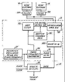
Figure 1 is a block diagram of one embodiment of the
present invention in which the trigger utilizes a D-Flop
circuit;
Figure 2 is a schematic of circuitry shown in block
diagram in Figure 1;
Figure 3 is a block diagram of an alternative embodiment
of the present invention in which a Comparator is used for
the trigger;
CA 02437465 2003-08-05
WO 02/063582 PCT/US02/02947
Figure 4 is a drawing of a sense electrode configuration
suitable for use with the block diagram as shown in Figures 1
or 3; and
Figure 5 is plot of measured change in capacitance of
sense electrodes shown in Figure 4 due to flat hand presence.
DETAILED DESCRIPTION
With reference to figure 1 there is shown a block
diagram of sensor electronics 10 in accordance with the
present invention. The circuit set forth is an example of
electronic circuitry for providing a control output signal in
response to a rate of change in capacitance of the sense
electrodes due to motion of the proximate object within the
field without intermediate electronic differentiation of
signals related to a change in capacitance.
The overall principle of operation is as follows: A
phase locked frequency control loop (PLL) 12 is
interconnected with sense electrodes 14 and 16. The PLL
includes a voltage controlled oscillator (VCO) 22 which has
an output, the frequency of which is linearly related to the
input control voltage 102. The output is connected to a
phase/frequency comparator via a frequency divider 100 and a
fixed phase delay network 34.
A reference oscillator 32 is also connected to the
comparator and generates a continuous fixed frequency signal.
The phase/frequency comparator 24 generally provides a high
voltage (Vcc) if the divided VCO frequency is lower than that
11
CA 02437465 2003-08-05
WO 02/063582 PCT/US02/02947
of the reference and a low voltage (0) if the divided VCO
frequency is higher than that of the reference.
Furthermore, when the two frequencies are equal but
there is a phase difference between them the comparator 24
detects the rising edges of the two signals and generates a
pulse output, the width of which is proportional to that
phase difference where this is between +/- 360 degrees. The
average loop control voltage is driven between 0 and Vcc in a
linear manner with the overall result that the
phase/frequency comparator tends to drive the rising edges of
both signals presented to it to a zero phase difference. When
this is achieved the PLL is thereby phase locked in such a
way that the phase of the divided VCO frequency is always
ahead of that of the reference frequency by the amount
defined by the phase delay network 34. This is the normal
quiescent state of the sensor.
In the preferred embodiment the frequency divider 100
divides the VCO frequency by 16 in order that the VCO runs at
16 times the frequency of the reference oscillator.
Utilizing a frequency divider in this way allows the use of
an inexpensive lower frequency, low power, reference
oscillator and is not otherwise essential for the basic
operation of the sensor. The VCO and phase/frequency
comparator may, for example, be elements of a CD74HC4046AM
chip manufactured by Texas Instruments.
The loop filter 20 is an RC network and it incorporates
a large capacitor which dominates the dynamic response of the
control loop. A small resistor is put in series with this
capacitor and connected to the VCO input 102. This resistor
12
CA 02437465 2003-08-05
WO 02/063582 PCT/US02/02947
allows the control loop to overpower a small amount of
circuit noise and thus stabilize the phase relationship
between the VCO and reference signals.
An additional feedback path 101 is also preferably
included which is connected in parallel with the loop filter
20. This is for eliminating false multiple trigger signals
which would otherwise occur in instances or applications
where very large phase delay errors are sometimes generated
due to very large dC/dt's occurring at the sense electrodes.
Such large signals could occur in applications where there
might be unusually rapid motion of the object being detected
or by motions of that object at close range.
Such instances of occasional large signals could occur
if the sensor is used to detect hand motion in a soap
dispenser application. This feedback path incorporates a
circuit which is adaptive to very large phase error signals
in such a way that for small error signals it provides
negligible output while for very large signals it does not
allow the phase difference to move out of the +/- 90 degree
range. In the preferred embodiment this parallel feedback
path incorporates two series diodes in the direction of phase
shift which causes a trigger and one diode in the opposite
direction together with an RC demodulating circuit. This
provides an alternate parallel path of feedback which the
phase error signal cannot overpower.
A sensitive phase comparator, such as for example, a D
type flip-flop 30 is connected to the reference oscillator 32
and the frequency divided VCO signal where the reference is
connected to the data input and the VCO is connected to the
13
CA 02437465 2003-08-05
WO 02/063582 PCT/US02/02947
clock input. This device is used as a trigger to generate
the sensor output signal. As the capacitance increases at
the sense electrodes due to movement of an object, such as a
hand (not shown), into the activation region and where this
is done at a sufficient rate to overpower the loop, the phase
between these signals will tend to shift. Whenever this
shift equals or exceeds the phase threshold set by the phase
delay network 34 the data input will be low instead of high
at the time of the clock transition and a trigger output
pulse will be generated.
It will be appreciated that the arrangement described
above is configured to detect only positive dC/dt's as
opposed to negative dC/dt's or both positive and negative
dC/dt's. This means that the sensor configuration described
above only generates an output when the object being detected
is moving towards the sense electrodes instead of away from
the sense electrodes. This mode of operation is by design
and is specifically advantageous in a soap dispenser
application where it is desired to have soap dispensed only
when a hand is moving towards the dispenser and not when the
hand is being withdrawn from the dispenser. This mode of
operation is appropriate for simplicity and intuitive ease of
use by typical users of a soap dispenser and also confers an
additional and advantageous performance feature which is
specific to a soap dispenser application.
This additional feature applies in the case when a user
requires additional or consecutive deliveries of soap which
therefore necessitates additional or consecutive generations
of sensor trigger signals. In this case, and because the
sensor is sensitive to positive dC/dt and adjusts to static
14
CA 02437465 2003-08-05
WO 02/063582 PCT/US02/02947
changes in capacitance, due for instance to that induced by
the static presence of a hand, the user does not need to
completely withdraw and reintroduce their hand into the
sensing region and may instead alternatively, simply advance
their hand further towards the sense electrodes or
alternatively move their hands up and down in small motions
within the activation region whereupon sensor activation and
soap delivery will occur upon the detection of each movement
towards the sense electrodes.
If required and advantageous for other applications, the
sensor circuit could readily be reconfigured to instead
detect negative dC/dt events where instead the trigger signal
would be generated if the object being detected is moving out
l5 of and away from the activation region instead of into and
towards it. Such a sensor could in principle be employed in
applications where it is desired to detect the motion of an
obj ect which is moving out of or being removed from within a
region.
The quiescent phase relationship can be set in one of
several ways but it is preferable to construct a phase delay
element 34 using a small RC network at the input to the phase
and frequency comparator 24. This forces the VCO oscillator
22 to run ahead of the reference oscillator 32 by an amount
to be balanced between the need for noise immunity and the
need for sensitivity. The closer the two phases run, the
more sensitive the trigger circuit. The larger the phase
shift between them the greater the tolerance for circuit
noise, and oscillator fitter. This element 34 sets the
triggering threshold.
CA 02437465 2003-08-05
WO 02/063582 PCT/US02/02947
In the case where the frequency of the reference
oscillator is about 32 kHz, the phase delay may be set to a
value in the range 0.5 to 4 ~,s, which is then equivalent to
about 6 to 45 degrees and is preferably set to a delay of 1.5
~,s .
With respect to RF interference, it is known that
capacitive sensors typical of the prior art are frequently
vulnerable to false activation due to the effects of stray
electromagnetic radiation. In the present invention a high
degree of immunity to RF interferences of this type accrues
due to the fact that the sensor is based on a PLL circuit
which is tuned, or operating at, a specific and low frequency
and which therefore has good inherent rejection of
frequencies which lie above and below that frequency.
Nevertheless, in application environments spurious RF
may occur which is sufficiently intense and at sufficient
frequencies so as to false trigger the sensor. In view of
this, in the preferred embodiment filters 103 and 104 are
connected between the sense electrodes and the VCO 22.
These filters reduce the magnitude of the intrusion into
the sensor circuit of high frequency signals due to stray or
spurious, extraneous RF interferences which may for example
be radiated by domestic kitchen appliances such as microwave
ovens and also by cell phones and which may otherwise be of
sufficient intensity to induce false activation of the
sensor. These filters may be comprised of ferrite filters,
however in the case of the soap dispenser application,
16
CA 02437465 2003-08-05
WO 02/063582 PCT/US02/02947
sufficient attenuation may be achieved using a simple network
of resistors and capacitors.
Figure 2 is a schematic diagram of a practical sensor
circuit 10 where the two sense electrodes are connected
directly to the points denoted by J1 and J2. In particular
this circuit also includes provision for utilization of a
shield electrode where the shield electrode is connected
directly to the connection point denoted by J3. This circuit
may be constructed on a printed circuit board by those of
customary skill in the art utilizing the components indicated
in figure 2. It should also be appreciated that if desired
for reasons concerning the economy of high volume mass
production, the circuit could be further refined and rendered
into a single integrated circuit electronic component known
as an application specific integrated circuit (ASIC) by those
of customary skill in the art.
The following mathematical representation of the dynamic
response of the sensor is provided in order to further
explain and illustrate the basic operation of the sensor.
The response of the circuit 10 will be different for
different shapes of the capacitance change over time. For
the soap dispenser application a reasonable approximation to
this shape is a ramp change in capacitance. Accordingly, the
solution to the analysis of the response of the circuit where
the trigger circuit is based on a D-flop and for a ramp
change in capacitance is given by:
c~en(t) = dCv . 1 1 _ e-s~w~t . cos( 1- ~~ . ~n . t) + ~ 2 ~ sin( 1- ~2 . ~n ~
t)
dt Cv ~ Tdelay - ~n2 ~ 1 _
17
CA 02437465 2003-08-05
WO 02/063582 PCT/US02/02947
where:
Ko - 2 ' ~ ' (F2 - Fl)
V2-Vl
Where:
Ko = gain constant
F1 - the VCO operating frequency
corresponding to the VCO control voltage
V1
F2 - the VCO operating frequency
corresponding to the VCO control voltage
V2.
In practice, and depending on the precise
characteristics of the specific device or devices used, the
gain constant, Ko as expressed in the above equation, is not
an exactly linear function of frequency and control voltage.
However, it is typically approximately linear over a certain
range of values. Moreover for design purposes, in general Ko
is a nonlinear function of a range of circuit parameters
which may be generically expressed by:
Ko = F(Vcc, N, try, R1, R2, C)
where:
Vcc - the supply voltage and is equal to
3.3V in the circuit depicted in figure 2.
N = number of times the VCO frequency is
divided due to circuit element 100
the reference oscillator 32 circular
frequency
18
CA 02437465 2003-08-05
WO 02/063582 PCT/US02/02947
R1 = resistance value corresponding on the
circuit diagram depicted in figure 2 to
R1
R2 = resistance value corresponding on the
circuit diagram depicted in figure 2 to
R2
and where the precise functional
relationship required for circuit design
purposes, denoted by f in the above
equation, may be determined from the
detailed data presented in vendor data
sheets which, for example, is variously
presented graphically in ~~CD54/74HC4046A
Texas Instruments Data Sheet, Feb. 1998,
revised May 2000.~~, which describes
operation of the particular PLL circuit
element depicted in figure 2.
VCO - the middle of the range of the
control voltage 102, i.e. Vcc/2 where Vcc
is the supply voltage and is equal to
3.3V in the circuit depicted in figure 2)
Vref - Reference voltage which is
internal to the PLL chip.
2 5 ~d = VCC
4~
z1=(R3+R4)~C
where:
R3, R4 and C are the loop filter
components (corresponding on the
19
CA 02437465 2003-08-05
WO 02/063582 PCT/US02/02947
circuit diagram depicted in figure 2
to R9, R8 and the capacitance C7.)
t = time
= the damping ratio which is given by:
~'=2~wn~z2
where:
z2 = R4 ~ C
The equation given above has a leading term which
multiplies a time dependent response term. The latter term
eventually declines to zero. The magnitude of the initial
response, which gives rise to the triggering, is therefore
proportional to the leading term and as such one can see that
it is proportional to the rate of change of capacitance
divided by the total capacitance. The initial response is
also inversely proportional to the natural frequency of the
loop circuit indicating as one would expect that the response
is greater for circuits which correct more slowly.
Figure 3 depicts a block diagram of the sensor
electronics 40 in accordance with an alternative embodiment
of the present invention., and includes common reference
numbers depicting identical or subsequently similar elements
described in connection with embodiment 10 shown in Figure 1.
In this embodiment 40, the trigger is based on a voltage
comparator 42. This is an alternate method of detection and
uses the control circuit of the phase locked loop (PLL) 12.
The operation is as follows: As with embodiment 10 shown in
figure l, the average control voltage is the voltage required
CA 02437465 2003-08-05
WO 02/063582 PCT/US02/02947
to cause the VCO 22 to operate at the same frequency, after
division, as the reference oscillator 32. In this embodiment
however there is no phase delay network and instead phase
shift errors will cause the phase/frequency comparator 24 to
increase or decrease the control voltage 102 until the phase
difference is corrected to zero. In this arrangement 40 the
phase error signal from the phase/frequency comparator 24 is
filtered by a first loop filter which may comprise an RC
network 44 and is also filtered by a second filter which may
also comprise an RC network 105 and which has a much longer
time constant than the first RC network and which provides a
voltage reference to the comparator 42. G~lhen the control
voltage 102 reaches a preset, positive going voltage
threshold at the comparator 42 , due to detection of a moving
object within the activation region of the sense electrodes
14 and 16, the comparator 42 actuates and provides the sensor
output trigger signal.
OPERATING FREQUENCY
The operating frequency of the sensor for a soap
dispenser (not shown) is the VCO frequency and is
approximately 0.5 MHz, (the actual frequency is 16 times the
reference oscillator frequency of 32.768kHz which equals
0.5244 MHz). This frequency is set to be sufficiently high
such that a person's hand is always detected by the sensor as
a dielectric material as opposed to a conductor sometimes and
a dielectric at others which could give rise to variability
in activation range and general performance. The issue
arises due to the fact that an individual operating the
dispenser may or may not be electrically grounded. For
instance the operator while requesting soap may at times have
21
CA 02437465 2003-08-05
WO 02/063582 PCT/US02/02947
one hand in contact with a grounded metal object such as a
sink or faucet or be connected to ground electrically by a
stream of running water.
In order for the person's hand to then be detected as a
dielectric, the frequency needs to exceed the free charge
relaxation time of the human body. This time is determined
from the product of the skin resistance to ground in ohms and
the body's capacitance in Farads. The capacitance of an
adult human is in the region of 50pF. The skin resistance
between two hands varies somewhere in the region of from 100
kS2 up to a few MS2. The RC time constant may therefore be as
short as 5 ~.s which corresponds to a frequency of 0.2 MHz.
The operating frequency of 0.5 MHz was therefore selected to
give a reasonable margin.
Other potential applications include faucet control.
The effective use of capacitive sensors for faucet control
may require significantly higher frequencies in the region of
10 MHz or higher. This is, for instance noted, in patent
5,730,165 and is generally also documented elsewhere. The
reasoning is again based on RC time contents and has to do
with the higher conductivities present in a sink environment.
There is no fundamental problem in modifying the design
of our sensor to operate at much higher frequencies if
desired. In fact, as far as frequency of operation is
concerned, the current state-of-the-art in PLL devices
extends well into the GHz region. Thus, this design could be
modified by "one of customary skills in the art" to operate
at any desired frequency up to the GHz region according to
the needs of the intended application.
22
CA 02437465 2003-08-05
WO 02/063582 PCT/US02/02947
Figure 4 illustrates a simulated soap dispenser base 50
having the electrodes 14, 16, formed from copper foil,
disposed in a spaced apart relationship for enabling the
establishment of an electric field therebetween. The side by
side arrangement gives rise to an electric field between the
two electrodes which extends outwards from the electrode
surfaces and curves between the two. The base 52 also
incorporates a shield electrode which in this instance is
formed from copper foil and wrapped around the outer side of
the base 52.
In this configuration, the magnitude of the field
strength declines nonlinearly with distance from the
electrodes 14, 16 as does also then the magnitude of the
change in capacitance due to the presence of a dielectric
material within that field, such as a hand. This kind of
side-by-side configuration gives rise to what may be termed a
fringing field and the sensor in combination with this
electrode configuration may be referred to as a fringing
field type of capacitive sensor. As a rough guide, the
intensity of the electric field typically declines rapidly in
a fringing field at distances which exceed the combined width
of the electrodes 14, 16 which. in this case is about 3
inches. The front to back extent is 3.1"; the side-to-side
extent is 3.25"; the separation is about 0.5"; the gap
between the electrodes and the shielded rim is about 1/" all
around.
The change in capacitance due to the presence of a hand
at different distance ranges from the simulated base was
measured. Figure 5 shows the changes in capacitance for an
23
CA 02437465 2003-08-05
WO 02/063582 PCT/US02/02947
adult hand, held flat at different vertical distance ranges
above the base 50 where a shield 52 was both present and
removed which. confirm this. There are two technical side
effects to the grounded shield 52. The first is that it
raises the overall capacitance of the sense electrode
structure by a few pF. The second is that it shunts a
portion of the electric field away from the sensing region
such that capacitance changes at a fixed distance range
decline. This is unavoidable for a grounded shield in close
proximity to the sense electrodes and is confirmed by the
data depicted in Figure 5.
Hence for this particular physical structure, the
requirement for shielding increases the required sensitivity
of the sensor and as confirmed by the test data described
herein this sensor has the necessary sensitivity. If
sensitivity should ever be an issue for this or other similar
applications requiring a similar shielded electrode, then an
alternative arrangement which would require less sensitivity
is to split the shielding and drive the two halves at the
same voltage as the sense electrodes.
SENSOR CHARACTERIZATION AND BENCH TEST DATA
The data falls into the following categories:
~ Characterization versus known small capacitance rates of
change
~ Characterization versus response to hand motion above
the simulated base
24
CA 02437465 2003-08-05
WO 02/063582 PCT/US02/02947
DYNAMIC SIMULATION AND TEST DATA
A test arrangement was constructed which was used for
characterization and as a means of generating a range of
known and reproducible capacitance variations at different
representative rates of change of capacitance occurring over
different timescales which are representative of hand motion
and with time profiles of capacitance change which
approximate a ramp. It is based on a parallel plate
capacitor comprising two flat parallel electrodes, which are
nominally 5 cm by 5 cm square and separated by a distance of
1 cm. Dielectric test samples comprising small squares of
pure fused silica measuring 3/8" square by 1 mm thick were
used to incrementally increase the capacitance. The material
has a known dielectric constant of 3.8.
The incremental increase in capacitance due to the
introduction of one such sample into the field region of ~ the
capacitor was calculated to be 6.3 fF given the actual
precise dimensions of the structure and test samples and
assuming a uniform field. A means was devised of introducing
and removing the sample into and out of the field region at a
known and constant speed. This comprised mounting the sample
on a thin plastic disc which traverses the field gap and
which is rotated by a small electric motor at a known RPM.
This arrangement thus provides a means for simulating rates
of change in capacitance due to hand motion.
The following motor RPM's were used where the test
sample was situated at the extreme outside edge of the
plastic disc. Each rotation gives rise to one positive dC/dt
CA 02437465 2003-08-05
WO 02/063582 PCT/US02/02947
as the sample enters the field between the plates and one
negative dC/dt as the sample leaves the field.
RPM t~,radians/svelocity, event duration, dC/dt,F/s
cm/s ms
13.5 1.42 7.9 140 45
23 2.41 13.4 82 77
32 3.35 18.6 59 107
Since each rotation gives rise to one positive dC/dt and
one negative dC/dt the arrangement also allows a test of
sensors triggering sensitivity to different dC/dt magnitudes
and false triggering to different -dC/dt's. This is also
useful since for the soap dispenser application the sensor
should not trigger due to hand removal from within the
activation region.
The following data relate to approximately 100
revolutions at each speed:
2 0 RPM Triggering percentage, % False triggering percentage,%
13.5 34 0
23 91 0
32 100 0
These data taken in combination with those of the
previous table, indicate that the sensor is sensitive to
events which exceed +77 fF/s with 82 ms duration and is 100%
(-1%) successful in these tests at detecting events of +107
fF/s with a duration of 59 ms.
The data also confirms that the sensor is capable of
reliably detecting the motion of a small dielectric object
other than a hand. The data also confirm that the sensor is
26
CA 02437465 2003-08-05
WO 02/063582 PCT/US02/02947
functional where the sense electrodes are disposed in a
parallel plate type configuration.
HAND ACTIVATION TEST DATA
In order to further provide evidence of reduction to
practice and suitability for application in the context of
activation of a non-contact soap dispenser, a series of hand
activation tests were performed using the simulated soap
dispenser base incorporating the fringing field configuration
of sense electrodes as well as a shield electrode as depicted
in Figure 4.
By referring to Figure 5, the required hand speed, can
be roughly estimated for reliable activation by approaching
vertically to activate the sensor at ranges of 3", 2" and 1".
The technical estimate can then be compared with actual data
for the same hand. The Lower curve indicates a change in
capacitance due to a hand at 3" range of about 5fF, about
l2fF at 2" and an estimated 39fF at 3". It can be estimated
that this change will accrue between an initial hand distance
of about 5" and the activation distance of 3" and so on. In
order for the rate of change to then be about 100fF/s the
hand speed will need to be about 100*2/5 inches per second -
40 inches per second for activation at 3" (50ms duration),
about 100*2/12 inches per second - 17 inches per second for
activation at 2" (120ms) and about 100*2/39 - 5 inches per
second for activation at 1"(444ms). 5 inches per second is a
very slow hand speed while 25 to 40 inches per second may be
more typical.
27
CA 02437465 2003-08-05
WO 02/063582 PCT/US02/02947
The sensor circuit was connected to the simulated base
and tested for activation by a hand moving towards the base
at what was judged to be normal speed and for repeat
activation when the hand is already within the activation
region, ten times for each case.
Test: Hand moved sideways into the activation region
Range, inches Activations False triggers
3 4 0
2.5 10 0
2 l0 0
Test: Hand moved vertically into the activation region
Range inches Activations False triggers
3 4 0
2.5 8 0
2 10 0
Test: Hand moved a to 1" vertically while within the activation region
2 0 Range, inches Activations False triggers
4 3 0
3.5 6 0
3 10 0
2.5 10 0
It should be appreciated that the above tests are
technical or 'staged' in the sense that care was taken to
keep the hand flat and level, which typical users of a soap
dispenser would not do, also hand speed is an important
factor and this was based on judgment of what might by
typical and this would vary in actual use. One can see that
according to these data the effective activation distance is
in the region of 2.5" to 3" and that this is also in
agreement with the technically based estimate. Similarly one
can see that there was zero incidence of false triggers
28
CA 02437465 2003-08-05
WO 02/063582 PCT/US02/02947
meaning that at no time was the sensor activated by hand
removal.
The electrical current draw for the circuit 10 is low
and substantially less than 1mA at low voltage. This
demonstrates suitability for long term operation using
alkaline batteries. This is advantageous for applications in
battery powered devices which are preferably intended for
continuous operation for extended periods without the need
for frequent battery replacement.
Although there has been hereinabove described a control
system in accordance with the present invention for the
purpose of illustrating the manner to which the invention may
by used to advantage, it should be appreciated that the
invention is not limited thereto. Accordingly, any and all
modifications, variations or equivalent arrangements which
may occur to those skilled in the art, should be considered
to be within the scope of the invention as defined by the
appended claims.
29