Sélection de la langue

Search

Sommaire du brevet 2438358 

Énoncé de désistement de responsabilité concernant l'information provenant de tiers

Une partie des informations de ce site Web a été fournie par des sources externes. Le gouvernement du Canada n'assume aucune responsabilité concernant la précision, l'actualité ou la fiabilité des informations fournies par les sources externes. Les utilisateurs qui désirent employer cette information devraient consulter directement la source des informations. Le contenu fourni par les sources externes n'est pas assujetti aux exigences sur les langues officielles, la protection des renseignements personnels et l'accessibilité.

Disponibilité de l'Abrégé et des Revendications

L'apparition de différences dans le texte et l'image des Revendications et de l'Abrégé dépend du moment auquel le document est publié. Les textes des Revendications et de l'Abrégé sont affichés :

  • lorsque la demande peut être examinée par le public;
  • lorsque le brevet est émis (délivrance).
(12) Demande de brevet: (11) CA 2438358
(54) Titre français: RACCORD DE DEVIATION
(54) Titre anglais: A DEFLECTION JOINT
Statut: Réputée abandonnée et au-delà du délai pour le rétablissement - en attente de la réponse à l’avis de communication rejetée
Données bibliographiques
(51) Classification internationale des brevets (CIB):
  • E21B 7/08 (2006.01)
  • E21B 17/02 (2006.01)
  • E21B 23/14 (2006.01)
(72) Inventeurs :
  • MOYES, PETER B. (Royaume-Uni)
(73) Titulaires :
  • WEATHERFORD/LAMB, INC.
(71) Demandeurs :
  • WEATHERFORD/LAMB, INC. (Etats-Unis d'Amérique)
(74) Agent: MARKS & CLERK
(74) Co-agent:
(45) Délivré:
(86) Date de dépôt PCT: 2002-02-15
(87) Mise à la disponibilité du public: 2002-08-29
Requête d'examen: 2003-08-13
Licence disponible: S.O.
Cédé au domaine public: S.O.
(25) Langue des documents déposés: Anglais

Traité de coopération en matière de brevets (PCT): Oui
(86) Numéro de la demande PCT: PCT/GB2002/000666
(87) Numéro de publication internationale PCT: WO 2002066779
(85) Entrée nationale: 2003-08-13

(30) Données de priorité de la demande:
Numéro de la demande Pays / territoire Date
0103803.3 (Royaume-Uni) 2001-02-16

Abrégés

Abrégé français

L'invention concerne un raccord de déviation (10) utilisé dans un forage (12) et comprenant un élément muni d'au moins un organe pivotant capable de pivoter autour d'un axe, et au moins un galet (30, 32, 34) destiné à réduire le frottement lorsque ce raccord de déviation se déplace dans ledit forage.


Abrégé anglais


A deflection joint (10) for use in a well bore (12) comprises: an element
provided with at least one pivot means pivotable about an axis; and at least
one roller means (30,32,34) for reducing friction when the deflection joint is
moved within said well bore.

Revendications

Note : Les revendications sont présentées dans la langue officielle dans laquelle elles ont été soumises.


5
CLAIMS:
1.~A deflection joint (10) for use in a well bore, the deflection joint (10)
comprising
an element (38, 40) provided with at least one pivot means (28) pivotable
about an axis
(29);
characterised by further comprising at least one roller means (30, 32, 34),
mounted for rotation about a rotation axis substantially parallel with said
axis (29) of
said pivot means (28), for reducing friction when the deflection joint (10) is
moved
within said well bore.
2. ~A deflection joint as claimed in claim 1, wherein at least one roller
means (30) is
positioned at said pivot means (28).
3. ~A deflection joint as claimed in claim 1 or 2, wherein at least one roller
means
(32) is positioned on one side of said pivot means (28), and a further roller
means (34)
is positioned on the other side of said pivot means (28).
4. ~A deflection joint as claimed in any preceding claim, which further
comprises
second pivot means (46), the two pivot means (28, 46) forming upper and lower
pivot
means,
and wherein at least one roller means (34) is positioned between said two
pivot
means (28, 46), one roller is positioned above said upper pivot means, and one
roller is
positioned below said lower pivot means.
5. ~A deflection joint as claimed in claim 4, wherein said upper and lower
pivot
means (28, 46) are arranged to pivot about parallel axes.
6. ~A deflection joint as claimed in claim 4, wherein said upper and lower
pivot
means (28, 46) are arranged to pivot about axes offset by up to 90 degrees.
7. ~A deflection joint as claimed in any preceding claim, wherein said element
is a
tubular element (38, 40).

6~
8. ~A deflection joint as claimed in any preceding claim, wherein at least one
pivot
means comprises an aligned ball joint (18).
9. ~A deflection joint as claimed in any preceding claim, wherein at least one
pivot
means comprises a pin joint (28).
10. ~A deflection joint as claimed in any preceding claim, which further
comprises at
least one swivel means (42, 44).
11. ~A deflection joint as claimed in any preceding claim, which comprises at
least
two swivel means (42, 44).
12. ~A deflection joint as claimed in claim 11, wherein one swivel means (42)
is
positioned on one side of said pivot means (28) and another swivel means (44)
is
positioned on the other side of said pivot means (28).
13. A deflection joint as claimed in claim 11 or 12, when also dependent
directly or
indirectly on claim 4, wherein one swivel means is positioned above said upper
pivot
means (46), and another swivel means is positioned below said lower pivot
means (28).

Description

Note : Les descriptions sont présentées dans la langue officielle dans laquelle elles ont été soumises.

1 1-04-LUU;i UG / 1 1 UJt
. ,
CA 02438358 2003-08-13
M&C Folio No P51915 WO
A Deflection Joint
The present invention relates to a deflection joint for use in well bores.
Oil and gas wells are becoming increasingly deviated, with wells tending to
follow optimised paths for producing hydrocarbons from a reservoir. In
addition,
multilateral wells having two or more producing well bores are becoming
increasingly
common. These well types tend to introduce bends in the well bore which can
introduce problems when accessing the well with wireline tools. When accessing
the
well with wireline tools, gravity is the primary rxleans of placing the
toolstring at the
desired position within the well. Any friction experienced through contact
between the
toolstring and the well bore significantly reduces the efficiency of the
toolstring.
Where a bend exists in a well bore it is normally necessary to include a
"knuckle
joint" in a wireline toolstring to allow the toolstring to bend to accommodate
the
curvature of the well bore. However, the inclusion of a conventional "knuckle
joint"
introduces a high load/high friction contact point with the well bore wall at
the point of
the bend. The contact at this point significantly increases the frictional
drag acting on
the toolstring, thus reducing the velocity of the toolstring as it is run into
or out of the
well bore. Additionally the high load acting on the contact point can result
in damage
to the toolstring and the well bore during running and whilst jarnng.
US 4,44.2,908 describes a drilling tool for deep wells having a motor-driven
drill
bit which can be turned at an angle to the axis of the primary well hole to
produce
lateral holes branching from the primary hole. The bit is rotatably-mounted in
the last
in a series of pivotally articulated links at the downhole end of the drill
pipe string. The
deviation of the drill bit from the well axis is controlled by pivoting the
last link with
respect to the penultimate link. The last link includes a sliding surface
which bears
against the wall of the well hole to effect the pivoting. In another form of
the invention
a spring effects the pivoting. Preferably stops are provided between the last
and
penultimate link to limit the angle of pivoting.
AMENDED SHEET

~ -U'+-GVVJ VGI 1 1 V:7~
CA 02438358 2003-08-13
MBcC Folio No P51915W0
US 5;033,558 describes a well tool for use in a down-hole drilling
assembly wherein the drill bit is rotated without drill pipe rotation
comprising a
generally tubular body and a plurality of roller assemblies secured to the
body, the roller
assemblies including rollers which rotate around axes generally transverse to
an axis
passing lengthwise through the body of the well tool.
According to the present invention there is provided a deflection joint as set
out
in the accompanying claims.
These and other aspects of the invention will become apparent from the
following description, when take in combination with the accompanying
drawings, in
which
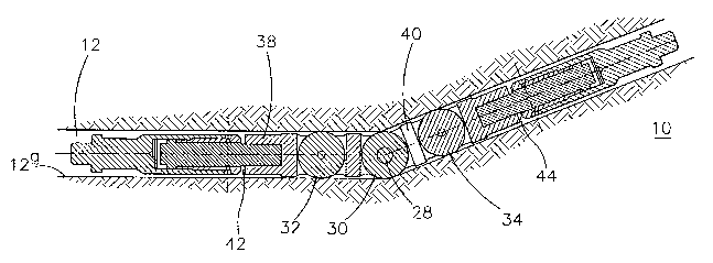
Fig. 1 is a cross-sectional view of a deflection joint in a deviated well bore
according to a preferred embodiment of the invention;
Fig. 2 is a perspective view of the deflection joint of Fig. l;
Fig. 3 is a cross-sectional view of a deflection joint in a deviated well bore
according to a second embodiment of the invention;
Fig. 4 is a perspective view of the deflection joint of Fig. 3;
Fig. 5 is an enlarged detail of the deflection joint of Fig. 4;
Fig. 6 is a cross-sectional view of a deflection joint in a deviated well bore
according to a third embodiment of the invention; and
Fig. 7 is a cross-sectional view of a deflection joint in a deviated well bore
according to a fourth embodiment of the invention.
With reference to Fig. I, a deflection joint, generally indicated by reference
AMENDED SHEET

1 1 -U't-GUUJ UG/ I 1 UW
CA 02438358 2003-08-13
M&C Polio No P51915w0 3
numeral 10; is shown in a deviated well bore 12. The deflection joint 10
comprises
tubular portions 38 and 40, a pin joint 28 positioned between tubular portions
38,40 and
rollers 30,32 and 34, which act to reduce the effects of friction, with roller
30 placed
directly onto the central pivotal pin joint 28 and rollers 32 and 34 located
in respective
tubular portions 38,40. Also provided are swivel joints 42 and 44 which allow
the
toolstring to move in a hole deviated in more than one plane. Rollers 30,32
and 34
protrude beyond the surface of the tubular element portions 38 and 40 and when
the
toolstring encounters a bend in the well bore, the tool 10 starts to pivot
about axis 29
only. As the tool bends the swivel joints 42 and 44 also rotate so that the
curvature of
the pin joint tool corresponds to the curvature of the well bore. As a result
of the
toolstring aligning itself to the well bore 12, rollers 30,32 and 34 come into
contact with
the well bore wall 12a thus minimising friction. In particular, with roller 30
being
placed at the point of the bend it provides friction reduction at the point
most likely to
be in contact with the well bore wall when running the toolstring into the
bore.
Figs. 3 and 4 show a second embodiment of the invention wherein a ball joint
18
is used as the pivoting means. In this embodiment the deflection joint 10
comprises
tubular portion 14 and 16, two rollers 20 and 22 and a swivel joint 24 which
allows the
toolstring to move into a hole deviated in one plane. With this arrangement
rollers 22,
20 are located in respective tubular portions 14 and 16. The ball joint 18
allows the
joint to bend about one axis 27 only. This is achieved by introducing
alignment plate 26
into the rear of the ball joint 18 as shown in Fig. 5. The deflection joint
operates in the
same manner as that shown in Fig. 1. .
Fig. 6 shows a third embodiment of the invention wherein a pin joint 28 is
used
as the pivoting means. In this embodiment one roller 30 is placed directly on
pin joint
28. Also provided are swivel means 42 and 44 which allow the toolstring to
move into
a hole deviated in more than one plane. The deflection joint operates in the
same
manner as that shown in Fig. 1.
Various modifications may be made to the embodiments hereinbefore described
without departing from the scope of the invention. For example, a swivel joint
may be
AMENDED SHEET

1 1 -V-T ~--vvV ...-. . . ..... .
,' CA 02438358 2003-08-13
I M&C Folio No P51915W0 4
placed in either of the tubular elements 38,40 or two swivel joints 42,44 may
be used
with joint 44 placed above the pivot means and the other joint 42 placed below
the pivot
means, as shown in Fig. 5. This allows the deflection joint to rotate freely
and
independently of the toalstring. The deflection joint may have two or more
pivot
means 28, 46 spaced apart, as shown in Fig. 7 of the drawings. This
arrangement
accommodates well bores with smaller radii of curvature more easily. For
example, if
two pivot means were used and the well bore radius of curvature is 4 degrees,
then each
pivot means need only bend by 2 degrees, and the angle of incidence on the
rollers
would thus be reduced. Furthermore, if the two pivot means were offset by 90
degrees,
this would allow -the deflection joint to bend in more than one plane.
An advantage of the arrangement disclosed in the above embodiments is that the
use of rollers on either side of the pivot means or, additionally, disposed on
the pivot
means, reduces the friction acting on the wireline toolstring when the
toolstring is being
moved into or removed from a well bore.
AMENDED SHEET

Dessin représentatif
Une figure unique qui représente un dessin illustrant l'invention.
États administratifs

2024-08-01 : Dans le cadre de la transition vers les Brevets de nouvelle génération (BNG), la base de données sur les brevets canadiens (BDBC) contient désormais un Historique d'événement plus détaillé, qui reproduit le Journal des événements de notre nouvelle solution interne.

Veuillez noter que les événements débutant par « Inactive : » se réfèrent à des événements qui ne sont plus utilisés dans notre nouvelle solution interne.

Pour une meilleure compréhension de l'état de la demande ou brevet qui figure sur cette page, la rubrique Mise en garde , et les descriptions de Brevet , Historique d'événement , Taxes périodiques et Historique des paiements devraient être consultées.

Historique d'événement

Description Date
Inactive : CIB de MCD 2006-03-12
Inactive : Morte - Aucune rép. à lettre officielle 2005-11-16
Demande non rétablie avant l'échéance 2005-11-16
Réputée abandonnée - omission de répondre à un avis sur les taxes pour le maintien en état 2005-02-15
Inactive : Renseign. sur l'état - Complets dès date d'ent. journ. 2005-01-05
Inactive : Abandon. - Aucune rép. à lettre officielle 2004-11-16
Inactive : Demande ad hoc documentée 2004-04-14
Modification reçue - modification volontaire 2004-03-24
Inactive : Lettre de courtoisie - Preuve 2003-10-21
Inactive : Page couverture publiée 2003-10-20
Inactive : IPRP reçu 2003-10-20
Lettre envoyée 2003-10-16
Inactive : Acc. récept. de l'entrée phase nat. - RE 2003-10-16
Inactive : CIB attribuée 2003-10-07
Inactive : CIB en 1re position 2003-10-07
Demande reçue - PCT 2003-09-22
Exigences pour l'entrée dans la phase nationale - jugée conforme 2003-08-13
Exigences pour une requête d'examen - jugée conforme 2003-08-13
Toutes les exigences pour l'examen - jugée conforme 2003-08-13
Demande publiée (accessible au public) 2002-08-29

Historique d'abandonnement

Date d'abandonnement Raison Date de rétablissement
2005-02-15

Taxes périodiques

Le dernier paiement a été reçu le 2003-08-13

Avis : Si le paiement en totalité n'a pas été reçu au plus tard à la date indiquée, une taxe supplémentaire peut être imposée, soit une des taxes suivantes :

  • taxe de rétablissement ;
  • taxe pour paiement en souffrance ; ou
  • taxe additionnelle pour le renversement d'une péremption réputée.

Veuillez vous référer à la page web des taxes sur les brevets de l'OPIC pour voir tous les montants actuels des taxes.

Historique des taxes

Type de taxes Anniversaire Échéance Date payée
Requête d'examen - générale 2003-08-13
TM (demande, 2e anniv.) - générale 02 2004-02-16 2003-08-13
Taxe nationale de base - générale 2003-08-13
Titulaires au dossier

Les titulaires actuels et antérieures au dossier sont affichés en ordre alphabétique.

Titulaires actuels au dossier
WEATHERFORD/LAMB, INC.
Titulaires antérieures au dossier
PETER B. MOYES
Les propriétaires antérieurs qui ne figurent pas dans la liste des « Propriétaires au dossier » apparaîtront dans d'autres documents au dossier.
Documents

Pour visionner les fichiers sélectionnés, entrer le code reCAPTCHA :


Pour visualiser une image, cliquer sur un lien dans la colonne description du document. Pour télécharger l'image (les images), cliquer l'une ou plusieurs cases à cocher dans la première colonne et ensuite cliquer sur le bouton "Télécharger sélection en format PDF (archive Zip)" ou le bouton "Télécharger sélection (en un fichier PDF fusionné)".

Liste des documents de brevet publiés et non publiés sur la BDBC .

Si vous avez des difficultés à accéder au contenu, veuillez communiquer avec le Centre de services à la clientèle au 1-866-997-1936, ou envoyer un courriel au Centre de service à la clientèle de l'OPIC.


Description du
Document 
Date
(aaaa-mm-jj) 
Nombre de pages   Taille de l'image (Ko) 
Description 2003-08-13 4 180
Dessins 2003-08-13 3 144
Dessin représentatif 2003-08-13 1 28
Revendications 2003-08-13 2 67
Abrégé 2003-08-13 1 62
Page couverture 2003-10-20 1 45
Description 2003-08-14 4 193
Revendications 2003-08-14 2 72
Accusé de réception de la requête d'examen 2003-10-16 1 173
Avis d'entree dans la phase nationale 2003-10-16 1 197
Demande de preuve ou de transfert manquant 2004-08-16 1 101
Courtoisie - Lettre d'abandon (lettre du bureau) 2004-12-29 1 166
Courtoisie - Lettre d'abandon (taxe de maintien en état) 2005-04-12 1 174
PCT 2003-08-13 8 310
Correspondance 2003-10-16 1 24
PCT 2003-08-14 10 440