Note : Les descriptions sont présentées dans la langue officielle dans laquelle elles ont été soumises.
CA 02438570 2003-08-18
Method and Apparatus for Monitoring
Underground Installations.
The invention relates to a method and apparatus for monitoring
underground installations which are subject to natural or forced flows, such
as ;,
tunnels, passages, canals, and the like. ,
To ensure high safety standards of underground traffic installations, "
extinguishing equipment installed therein must be released by fire alarm
devices in order to limit or prevent the spread of the fire early, i.e. during
its
development phase already. For this purpose it is known to install detectors
along the ceiling of a tunnel. For instance, in the ADW 511 Transafe system,
the linear heat detector, a copper sensing tube filled with a gas, is
installed
along the ceiling of a tunnel. The change in pressure caused by localized
heating is immediately sensed by an electronic pressure receiver connected
to an end of the tube (homepagelwebsite of SecuriSens Company). To
prevent false measurements, the pressure extant in the tube must be
monitored continuously. To this end, a test motor is provided which at regular
intervals generates a predetermined super pressure in the tube. The actual
pressure increase is compared with this pressure which serves quasi as a
reference parameter measurement value. In case of deviations of the
' measured pressure from the test pressure a signal is released. The
necessary test motor as well as the procedure require an additional effort.
The heat sensor cable TSC 511 which has become known by way of
the website of the SecuriSens Company as well, is based on a similar
principle. In this case the installation also extends over long measuring
distances. Regularly monitored small temperature sensors are applied to a
Attorney Docket 030588
PCT/DE02100411
CA 02438570 2003-08-18
shielded flat ribbon cable which serves as a data and storage bus. Based
upon predetermined values, an evaluation circuit decides when a signal has
to be released in response to an inadmissibly high heat increase.
The disadvantage of those two thermal monitoring processes is that
they require relative dear line alarms. It is also known from practical
experience that signaling a localized increase in temperature near the ceiling
of a tunnel is unsuitable for an early detection of a fire since at the time
the
signal is released the fire may already have spread in a hazardous way.
Moreover, the unpredictable flow conditions prevailing in a tunnel do not
admit of a reliable localized fire detection.
It has also become known to install suction nozzles along the ceiling of
a tunnel. The air sucked in by these nozzles is fed to detectors which
examine the air for fire, smoke and toxic gasses. In case a maximum
concentration is exceeded, an alarm signal is dispatched to a monitoring
center, and an extinguishing device is activated. Such smoke suction
systems are being offered, for instance, by prospectus sheets of the company
Wagner Alarm and Sicherungssysteme GmbH. of Langenhagen. However,
practical applications have demonstrated the unreliability of such fire alarm
systems. As set forth in the article of Siemens, Cerberus Division,
Maenndorf, Switzerland, the reasons for this must be sought chiefly in the
unpredictability of flow conditions of the kind prevailing in underground
traffic
systems (Maergele, R., "Branddetektion and Loeschung von Tunnelbraenden
im Test", S + S Report, 212000, pp. 36-41 ). As a consequence, alarms are
released too late and locally very imprecise. A further disadvantage of such
fire alarm techniques is that very dear detectors are used for distinguishing
fire and smoke gasses from fog and common automotive exhaust emissions
for preventing false alarms. In practical applications the installation
density of
such detectors is kept very low for reasons of costs. Consequently, the site
where the fire develops cannot be determined accurately. For a safe
constriction of a fire it must, however, be localized with a precision of but
a
Attorney Docket 030588
PCT/DE02100411
CA 02438570 2003-08-18
few meters.
For limiting false alarms of fire extinguishers, it has been proposed
initially to connect signals released by smoke gas detectors to command
centers which are monitored by trained operators. Following an examination
by the operators, they are to make a decision about releasing the
extinguishing system. Not only would such an approach be extremely
expensive, but because of subjective erroneous assumptions it would be
subject to too high a risk.
Fire detection which is more reliable and, above all, independent of
flows prevailing in a tunnel is to be made possible by a heat detector system
also linearly installed in a tunnel. A laser pulse propagating through a fiber-
optical cable is changed as a result of partial warming of the cable. Since as
stated in the publication referred to above (see page 41, top of column 1 )
the
rising temperature of the cable is cause. solely by the radiation heat of the
fire
which is not affected by wind in the tunnel; the site of the fire may be
determined accurately. However, the disadvantage of such fire alarm cable in
real traffic systems, even without test results, is obvious: Because of its
complicated structure and because of its components, the cable is very
expensive and it is combustible. Moreover, the evaluation of the signals and
the localizing of the fire requires complex software.
The object of the invention is, therefore, the provide a method of
monitoring underground installations which at an economically responsible
" cost offers a high degree of reliability. It is to make possible quick
detection
and spatially precise localization of fires as well as an accurate
distinction,
when using gas detectors, of smoke and fire gasses from vehicle emission
gasses. Simple and robust detectors are to be used in the devices required
for this purpose. Finally, the requirements as regards evaluation software,
relative to the approaches referred to above, are to be significantly lower.
Attorney Docket 030588
PCT/DE02/00411
CA 02438570 2003-08-18
In accordance with the invention, the object is accomplished by the
elements of patent claim 1. Patent claims 2 to 4 present advantageous
procedural ways. Patent claim 5 relates to an apparatus for monitoring
underground installations in which the measuring plane is arranged
transversely of the flow direction of the air. The following patent claims 6
and
7 relate to defined arrangements of detectors within the measuring plane.
The new method meets the requirement of detecting and precisely
locating, as quickly as possible, any impermissible change in the physical or
chemical properties of air within the underground installation. In this
connection; the way in which the detection is carried out is unimportant. By
the detection in accordance with the invention transversely of the direction
of
air flow, the detector or detector positioned closest to the cause of the
change
wiN provide the decisive contribution to the sum signal detected by
integration
over the entire plane. Even higher wind velocities will be without essential
effect as regards the detection since.the detectors are not only arranged at
the ceiling but also in the area of the walls and of the floor of the
structural
system. The invention offers the additional advantage that in the case of an
installation of individual detectors relative unsensitive and, hence,
inexpensive detectors may be used, such as, for instance, optical detectors,
which deliver a signal only upon reaching a predetermined status. In the case
of smoke detectors installed along the structural clearance profile it is no
longer their high sensitivity which matters, but simply the response of the
detectors reached by the smoke gas. These detectors need not be capable
of distinguishing between automotive emissions gasses and truly dangerous
smoke gasses. By integrating all detectors disposed within a measuring
plane, information can be obtained about toxic gas relative to a
predetermined and spatially precisely defined cross-section of the system.
The sum signal obtained makes it possible to distinguish, without any
difficulties, between a short-time localized and quickly dissipating eruption
of
vehicular emission gasses and a continuous or increasing emission of
combustion gasses. Even though all changes in physical andlor chemical
Attorney Docket 030588
PCTIDE02/00411
CA 02438570 2003-08-18
properties are, of course, registered, exclusively spot-like changes of the
properties do not initially release a signal. Thus, a short-time response of
individual detectors does not release a false alarm.
An economically particularly advantageous variant of the invention
resides in the installation of suction nozzles or openings distributed in a
manner appropriate for prevailing flow conditions, for continuously sucking in
air. The mixture resulting from the sum of the air sucked in by all of the
nozzles is compared with a threshold value by way of a detection and
evaluation device provided in every measuring plane. For this purpose, the
detector may be of simple structure since it need signal only different
concentrations of a toxic gas in the suck-in air, father than their
composition,
Such detectors need not be of high sensitivity. They only release a signal, if
the concentration of a toxic gas in the sucked-in air exceeds the set
threshold
value. It is important that the evaluation circuit which has been reached by
the air-toxic gas mixture, recognizes it as such. By arranging suction nozzles
in the area of the floor of the underground installation it is possible to
detect
toxic gases the density of which is greater than air. Since the set threshold
value is only exceeded if several suction nozzles suck in toxic gas over a
longer period of time or if, in case of a fire, smoke gas is sucked in by
several
nozzles in a short time, that is to say if an abrupt quantitative increase of
toxic
gas is detected, can hazardous gasses be safely distinguished from air
changes caused by an increased traffic volume or a traffic jam. A locally high
concentration of locally and temporally limited vehicular gas emissions
registered by one or two detectors, does not reach the set integrated toxic
" gas threshold concentration. Thus, vehicular gas emissions can no longer
release a false alarm. Since several measuring planes are distributed over
the entire length of the underground installation, the site where the toxic
gas
emission is generated can be defined precisely.
The safety of underground installations can be increased further by
arranging sensors in a measuring plane which detect different properties or
Attorney Docket 030588
PCTIDE02100411
CA 02438570 2003-08-18
by installing optical and thermal detectors in addition to suction nozzles. By
using detectors which are more economical, subject to fewer malfunctions
and less maintenance this can be done economically.
The invention will hereafter be explained in greater detail with
reference to an embodiment. In the appurtenant drawings:
Fig. 1 is a schematic view of a fire alarm system in a tunnel, based on the
principle of air suction;
Fig. 2 shows a fire alarm system based on the principle of sensors installed
in a measuring plane; and
Fig. 3 is a cross-section of the tunnel of Fig. 1.
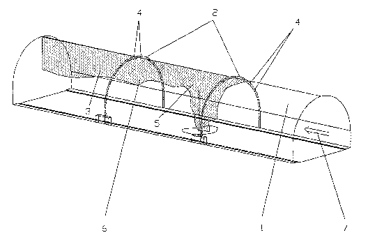
Figs. 1 and 2 each depict a section of a traffic tunnel the structural
clearance profile of which is limited by a vaulted tunnel wall 1. In Fig. 1,
following the profile of the structural clearance, two tubular arches 2 are
installed at a distance of about 50 m from each other, one tubular end of
which enters into a detection device 3 not shown in detail. Suction openings
4 are disposed equally spaced along the circumference of the tubular arches.
In terms of flow characteristics their opening diameters are such that at
constant suction power the same flow volume per unit of time is sucked in at
each opening. A fire 5 resulting in intensive smoke development is present
on the floor of the traffic tunnel. The smoke 6 from the fire is spreading in
the
direction of the air flow 7 prevailing in the traffic tunnel and shown by an
arrow. Whilst the suction openings 4 of the tubular arch 2 placed first in the
.
direction of flow are still inhaling normal tunnel air, the air sucked into
the
consecutive tubular arch 2 already contains a considerable proportion of
smoke. The section of the traffic tunnel disposed forwardly of the detecting
tubular arch 2 will be indicated as the source of the smoke from the fire.
By way of difference from Fig. 1, Fig. 2 shows detectors 8 installed on
the tunnel wall 1 instead of tubular arches 2. A signal line extends from each
Attorney Docket 030588
PCTlDE02l00411
CA 02438570 2003-08-18
detector 8 to an evaluation unit 9 not shown in detail, where, depending upon
the evaluation mode, the individual signals detected in a given measuring
plane are integrated. The information thus gained is compared against a
predetermined threshold value and if it is exceeded, an alarm signal will be
released. The detectors 8 used may be of simple structure, such as optical
detectors, smoke detectors or temperature detectors. Since each of them
only signals a predetermined status, i.e. the presence of a defined physical
or
chemical condition, but no data about intensity, quality or admissibility of
this
condition, this variant also allows the use of simple and economical
detectors.
Unly the integration of all values measured within a measuring plane delivers
the desired information, i.e. data which is factually correct for a correct
interpretation of the prevailing condition.
The essence of the invention becomes particularly apparent from the
cross-sectional view of the tunnel shown in Fig. 3.1n case of a fire, smoke 6
will collect under the ceiling of the tunnel within a short time. All suction
openings 4 in tubular arches 2 disposed, in the direction of flow, in the area
behind the fire 5, suck in the smoke 6. These suction openings 4 are more
than one third of all the suction openings. The mixture of smoke and air
arriving at the detector device 3 is immediately recognized as hazardous, so
that an alarm will be released. By contrast, the gas emitted from an upwardly
directed exhaust pipe of a truck will be sucked in along the entire length of
the
tunnel by but one or two suction openings 4, so that the air-emission gas
mixture does not attain the critical concentration necessary to release an
alarm.
The same holds true if, as shown in Fig. 2, detectors 8 are provided
instead of suction openings 4. The detectors 8 arranged at the highest point
of the tunnel wall 1 act in the manner of a linear detector along the entire
length of the tunnel. Detors 8 successively responding at short intervals over
the entire length of the tunnel indicate a passing vehicle with an upwardly
directed exhaust pipe. If the gas is emitted downwardly laterally of the
vehicle, the detector 8 in the immediate vicinity will deliver a signal, but
the
Attorney Docket 030588
PCTIDE02100411
CA 02438570 2003-08-18
evaluation unit 9, by comparing the signal with other signals from the
remaining detectors 8 disposed in the same measuring plane, will not~release .
an alarm because of the small proportion of the signal relative to the total
number of detectors 8.
Attorney Docket 030588
PCTlDE02100411