Note : Les descriptions sont présentées dans la langue officielle dans laquelle elles ont été soumises.
CA 02438632 2003-08-29
LAMINATED CROSS LUMBER AND METHOD OF MAKING SAME
BACKGROUND OF THE INVENTION
Field of the Invention
The present invention relates to static wood
s structures. More particularly, the present invention relates
to a method for making a laminated wood product.
Background Art
A variety of laminated wood beams are used in
construction work today as joists, girders, posts, columns
~o or other structural pieces. Laminated wood beams are known
to be stronger, more resistant and more dimensionally stable
than continuous wood beams. Unfortunately, the fabrication
of traditional laminated beams requires the use of wood
members of dimensions and quality that have become
i5 increasingly harder to obtain due to the fact that nowadays
the trees available are a lot smaller than they once were.
Thus, the wood members are often cut from trees of
relatively small diameter, such as trees from plantation or
northern forests, thereby producing members of low grade,
zo small dimensions and with a high proportion of flash.
Also, the cutting of wood for various elements
required in construction work generates a great quantity of
pieces of small dimensions, difficult to reuse thus usually
considered as waste. This high proportion of wasted material
z5 greatly increases fabrication costs.
Accordingly, a number of alternative laminated
wood products methods have been developed in order to be
able to use smaller wood members and/or wood members of
lower grade. One example of such a product is presented in
3o US Patent No. 4,568,577 issued February 4, 1996 to
Fischetti, where squared timbers of uniform thickness are
joined edge to edge and end to end in order to form a
laminated structure with at least one longitudinal void.
While this configuration allows for the recycling of timbers
-1-
CA 02438632 2003-08-29
of small length by joining them end to end through a pencil
joint, it does not allow the use of timbers of varying
thicknesses. Moreover, defects such as flash must be removed
before assembling the timbers, thereby reducing the
proportion of waste material that can be reused.
A number of alternative methods gave also been
developed to produce laminated wood products. US Patent No.
6,466,412 issued September 10, 2002 to Mathis presents a
method of making glulam wood beams using strips of planks of
io identical thickness glued side to side. Careful planning in
the placement of the planks of various widths is needed to
avoid aligned joints in the beam causing beam weakness. If
the joints between planks are aligned, a strip can be cut
from the beam perpendicularly to the original strips and
then attached thereto to reinforce the beam. However, this
additional strip greatly increases the time and costs of
manufacturing by augmenting the number of steps in the
process.
CA Patent Application No. 2,350,380 filed June 13,
zo 2001 by Grenier presents a method for making a lamellated
wood product of high mechanical properties from wood slats
of uniform thickness. The wood slats are bonded end to end
to a desired length and edge bonded into a panel, the panel
is cut into smaller panels of identical width, the small
z5 panels are face bonded to form a beam, the beam is cut to
form smaller beams, and the small beams are cut into
lamellated wood product. This process requires numerous
steps in order to obtain the final product. Moreover, the
requirement of uniform thickness prevents the use of slats
3o containing defects such as flash.
Accordingly, there is a need for a method of
making laminated wood beams that requires a minimum of
steps, while easily integrating the use of potential waste
material such as small wood members of non standard
35 dimensions and wood members containing flash.
-2-
CA 02438632 2003-08-29
SUN~?ARY OF INVENTION
It is therefore an aim of the present invention to
provide a method for making a laminated cross lumber beam
that is simple.
s It is another aim of the present invention to
provide a method for making a laminated cross lumber beam
that can be further simplified by the use of small wood
members.
It yet another aim of the present invention to
~o provide a method for making a laminated cross lumber beam
that easily integrates the use of wood members containing
flash.
It is an additional aim of the present invention
to provide a method for making a laminated cross lumber beam
~s that easily integrates the use of wood members of non
standard dimensions.
It is a further aim of the present invention to provide a
method for making a laminated cross lumber beam that
produces a beam of superior mechanical properties and
2o pleasing visual appearance.
Therefore, in accordance with the present
invention, there is provided a method for making a laminated
cross lumber beam comprising the steps of:
a) Providing a plurality of elongated wood members,
2s each having a top longitudinal face and a bottom
longitudinal face extending between a pair of opposed
longitudinal sides;
b) Stacking a plurality of elongated wood members with
the top and bottom longitudinal faces of adjacent
3o stacked elongated wood members bonded to one another
along a bonding plane such as to form a number of
intermediary beams of similar height generally
corresponding to a desired height of the laminated
cross lumber beam to be made;
3s c) Cutting each intermediary beam having a width
greater than a predetermined value: along a lengthwise
plane generally perpendicular to the bonding planes
-3-
CA 02438632 2003-08-29
thereof such as to form a plurality of panels, the
panels and uncut intermediary beams forming sub-beam
elements having opposed longitudinal sides generally
perpendicular to the bonding planes thereof;
s d) Joining at least two sub-beam elements together with
opposed facing longitudinal sides of adjacent sub-beam
elements bonded to one another to form the laminated
cross lumber beam.
Further in accordance with the present invention,
~o there is provided a method for making a laminated wood
timber from a plurality of elongated wood members,
comprising the steps of:
a) Using the wood members to make at least two
laminated beams having a width corresponding generally
is to a width of the elongated wood members, wherein a
plurality of the wood members are joined together face
to face along joining planes to form each of the
laminated beams;
b) Cutting lengthwise the laminated beams having a
zo width greater than a predetermined value into panels,
the panels and uncut laminated beams forming sub-timber
elements, each sub-timber element having longitudinal
sides generally perpendicular to the joining planes
thereof;
z5 c) joining at least two sub-timber elements side by
side to form a laminated wood timber.
BRIEF DESCRIPTION OF THE DRAWINGS
Having thus generally described the nature of the
invention, reference will now be made to the accompanying
3o drawings, showing by way of illustration a preferred
embodiment thereof and in which:
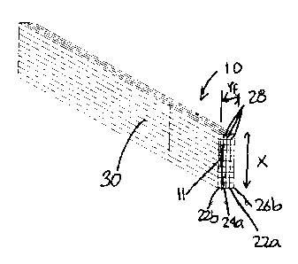
Fig.l is a perspective view of a laminated cross
lumber beam according to a preferred embodiment of the
present invention;
-4-
CA 02438632 2003-08-29
Fig.2A to 2C are perspective views of wood members
used as starting material in the method according to a
preferred embodiment of the present invention;
Fig.3 is a perspective view of a beam obtained by the face
s to face lamination of the wood members;
Fig.4 is a perspective view showing the step of
cutting the beam shown in Fig.3;
Fig.5 is a perspective view of panels produced by
the cutting operation illustrated in Fig.4; and
~o Fig.6 is a perspective view illustrating the step
of joining two panels to provide for the fabrication of
beams of greater length.
DESCRIPTION OF THE PREFERRED EMBODIMENTS
Referring now to Fig. l, a laminated cross lumber
15 beam or timber 10 is composed of a plurality of elongated
wood pieces 11 bonded together face to face and side to
side. This laminated cross lumber beam 10 presents the
advantages of superior mechanical and physical properties
and a visual aspect similar to a standard laminated beam,
zo while being produced using a simple method that can be
further simplified by the use of small wood members as a
starting material. The simplicity of the process minimizes
fabrication costs. The method used to produce this laminated
cross lumber beam is described in the following.
z5 The starting material for the method according to
the present invention is a plurality of elongated wood
members. 12. The wood members 12 include two longitudinal
sides 14 and top and bottom wider longitudinal faces 16.
Shown in Fig.2 are different examples of wood members 12
3o that can be used: integral members (Fig.2A), smaller members
joined end to end through finger joints 18 or any other
appropriate joints (Fig.2B), and members partially composed
of flash 20 (Fig.2C). The wood members 12 are preferably
made of high density softwood such as black spruce or jack
35 pine of low grade (no. 3 and/or economy). Of course, other
-5-
CA 02438632 2003-08-29
types and grades of wood can be used, as needed. The wood
members also need to have an appropriate humidity content,
for example between 12o and 150. Preferred dimensions for
the wood members are a thickness (Xl) of 0.75 to 2 inches, a
s width (Y) of I.5 to 8 inches and a length (Z) of 6 inches to
20 feet, but of course any other appropriate dimensions can
be used.
An optional preliminary step of evening the
dimensions of the wood members 12 can be performed, for
~o example by planing. This can be done t:o eliminate all or
part of the variations in width and/or thickness within the
wood members 12, thereby optimizing the adhesion between
adjacent wood members 12 by increasing the surface of
contact therebetween. This step also allows the removal of
at least part of the flash 20 if so desired. The wood
members 12 are selected and/or transformed so as to obtain
groups of wood members 12 of similar width (Y).
Glue is then put on the longitudinal faces 16 of the wood
members I2 of similar width (Y) before pressing them
zo together face to face in order to form a beam 22 as shown in
Fig.3. For a product required to perform according
to mechanical criteria, the glue used is preferably a
structural wood glue such as polyurethane (PUR),
isocyanates, phenol-resorcinol-formaldehyde (PRF),
zs resorcinol or any other appropriate adhesive. For a product
required to perform according to chemical criteria, a non-
structural wood glue can be used, such as polyvinyl acetate
(PVA), urea melamine (UM), urea formaldehyde (UF), or any
other appropriate adhesive. The thickness (X) of the beam 22
3o is the sum of the thicknesses (X1) of the wood members 12
used, whereas the width (Y) of the beam 22 is determined by
the width of the widest wood member 12 used.
If required, a step of planing the beam 22 can
then be performed in order to obtain a more uniform width
35 (Y). This can be done, for example,. by longitudinally
running the beam 22 through an edging station. This step
-6-
CA 02438632 2003-08-29
also allows for removal of at least part of the flash 20 if
so desired.
The beam 22 is then cut perpendicularly to the
longitudinal faces 16 of the wood members 12 as shown in
s Fig.4. This will produce a number of panels 22a,b,c having a
smaller width (Y') that can be, for example, between 0.5 and
4 inches . For beams 22 that have a small enough width ( for
example, 2 inches or less), this step can be omitted. Thus,
the method of the invention can be simplified when the
~o starting material is smaller.
Some of the panels 22a,b,c, 24a,b,c, 26a,b,c are
then pressed and glued together along faces 28 parallel to
the longitudinal sides of the wood members 12 to produce the
laminated cross lumber beam 10, as shown in Fig.l. The
adhesive used can be the same as previously used or another
appropriate adhesive. The width (Yf) of the laminated cross
lumber beam 10 is the sum of the widths (Y' ) of the panels
used, whereas the height (X) of the laminated cross lumber
beam 10 is determined by sum of the thicknesses (X1) of the
2o wood members 12 used. Of course, small beams that have not
been cut into panels are assembled in a similar manner, and
can be used alone or in combination with panels to form a
laminated cross lumber beam 10. In a preferred embodiment,
the panels are selected so that adjacent panels come from
z5 different beams (see Fig.5 in conjunction with Fig.l). In
the example shown, a panel 24a from beam 24 is sandwiched
between panels 22b and 22a from beam 22, panel 22a being
also adjacent to a panel 26b from beam 26. This distribution
favors the discontinuity of wood fibers between the panels
3o and optimizes the distribution of weakness points within the
laminated cross lumber beam 10. Thus, a better distribution
of internal forces can be achieved, causing a low
variability in mechanical properties between different
laminated cross lumber beams 10. Selecting the panels also
35 allows to place panels with a better visual appearance to
form the exterior surfaces 30, thereby improving the
esthetic qualities of the laminated cross lumber beam 10.
CA 02438632 2003-08-29
To produce longer laminated cross section beams
10, the panels (here 22b and 22c) can be joined end to end,
as shown in Fig.6. Preferably, the joint 32 is S-typed
combined with an appropriate adhesive, but any other
equivalent joint can be used. For structural reasons, it is
preferable that joints are not aligned between assembled
adjacent panels in the laminated cross section beam 10. Of
course, it is also possible to join together entire sections
of laminated cross section beam 10 as well, using any
io appropriate type of joint.
Finally, if required, a planing of surfaces of the
laminated cross section beam is done ~>o as to obtain the
final desired dimensions.
The described method presents several advantages,
~5 one of which, as stated above, being the fact that the use
of smaller starting material simplifies the fabrication
process by allowing the omission of a step, namely the
cutting of the beams into panels. Thus, this method allows
for easy recuperation of scrap wood of small dimensions.
2o This method also allows the use of other scrap wood, such as
wood members of non standard dimensions and wood members
containing flash, either as is or after removing it
completely or partially. Moreover, this method allows for
the positioning of the panel pieces in the laminated cross
z5 lumber beam in order to maximize mechanical properties and
esthetic appearance. The laminated cross lumber beam has
mechanical properties superior to the wood members composing
it as well as a low variability of these properties between
laminated cross lumber beams, namely because of wood fiber
3o discontinuity and the distribution of weakness points
brought by the cross lumber positioning of the panels.
Finally, the laminated cross lumber beams produced by this
method are produced rapidly in a minimum of steps, thus
minimizing costs by diminishing handling, required equipment
ss and workers, etc.
It will be appreciated that the invention is not
limited to the specific embodiments described, which are
_g_
CA 02438632 2003-08-29
merely illustrative. Modifications and variations will be
readily apparent to those skilled in the art. Accordingly,
the scope of the invention is deemed t:o be in accordance
with the claims as set forth below.
_g_