Note : Les descriptions sont présentées dans la langue officielle dans laquelle elles ont été soumises.
CA 02439169 2003-08-07
1
DEVICE FOR CONTAINING, REACTING AND MEASURING, AND METHOD OF
CONTAINING, REACTING AND MEASURING
TECHNICAL FIELD
The present invention relates to a device for containing, reacting and
measuring,
and a method of containing, reacting and measuring. The invention relates to
all manner
of fields which require the handling of low molecular weight organisms and
biopolymers
such as genes, immune systems, amino acids, proteins and sugars, including for
example
the fields of engineering, agricultural science incorporating foodstuffs,
agricultural
production and seafood processing, pharmaceuticals, the medical field
incorporating
hygiene, health, immunity, disease and genetics, and scientific fields such as
chemistry
and biology.
In particular, the present invention relates to a device for containing,
reacting and
measuring and a method of containing, reacting and measuring which is suitable
for the
analysis of genes including mutational analysis, polymorphic analysis,
mapping, base
sequence analysis, and mechanism analysis.
BACKGROUND ART
Currently, when determining gene base sequences a DNA chip is used.
This DNA chip is a flat sheet comprising a semiconductor film or a slide glass
on
to which is spotted a minute quantity of suspensions of a large number of
different, known
oligonucleotides, with the oligonucleotides fixed in an array pattern
sequence. The DNA
chip is made by using a pipette apparatus in order to form a plurality of the
oligonucleotides on the restricted surface thereof, minute quantities of
oligonucleotide
suspensions being dispensed spot by spot on to the surface while leaving a
predetermined
separation between adjacent spots to prevent mixing. By using such a DNA chip,
various
assay or analysis related to genes is performed.
For example, in determining the base sequence of an unknown target gene,
conventionally the user pours a liquid with the target genetic material
suspended therein
and which is labeled with a luminescent material, onto the DNA chip. Then
after leaving
for a fixed reaction time, the surplus suspension is removed by washing.
Subsequently,
the luminescence from the DNA chip is detected to thereby determine the base
sequence
from the position where the luminescence is detected.
CA 02439169 2008-02-05
2
However, in order to manufacture the DNA chip, with the arrangement of a large
number
of different oligonucleotides at a high density in a plane on a restricted
region, not only is
there the likelihood of cross-contamination occurring due to these becoming
close to each
other, but also the oligonucleotides at each of the fixed positions becomes an
even smaller
amount. In particular, if the oligonucleotides at each of the fixed positions
becomes a
small amount, determining the luminescence position is susceptible to error so
that there is
a problem with accuracy.
Furthermore, heretofore a DNA chip with substances such as oligonucleotides
fixed to the plane surface of for example a glass plate of a prepared slide of
a size of for
example approximately 2.6cm x 7.6cm is used. In supplying a liquid to this
substance
such as the oligonucleotide which is at the fixed positions on the plane
surface, a method
is used where liquid of around several 10 liters is dispensed onto the plane
surface, and
then the glass plate or a film is mounted in a sandwich condition on the flat
surface by
hand, so that a uniform thin liquid layer is formed to supply a small amount
of liquid
evenly to the respective fixed positions. With this method, the step for
mounting the film
or the like is necessary, and hence this becomes an obstacle to automation of
the operation.
Moreover, fluidization of the liquid for supply in order to supply the liquid
by mounting
the film or the like, is problematic. Furthermore, due to miniaturization
there are
problems in that the encounter characteristics or reactivity of the target
substance are more
and more reduced, so that processing takes time, and for the processing a high
density
liquid is necessary.
Moreover, since the sample is arranged in a plane, then with higher densities,
the
handling and automation thereof is even more difficult. Consequently, the
manufacture of
the DNA chip requires a considerable amount of effort and time, resulting in
high cost. In
particular, in performing analysis, assay or determination of the structure of
large amounts
of unknown target substances which contain base sequences, the analysis, assay
etc. of a
large amount of DNA chips is necessary. Therefore, the present applicant in
order to
solve this problem has disclosed in WO01/53831, WO0l/61361 and WO01/69249 an
integrated support which has one, or two or more long slender base members of
for
example filaments, fibers, tapes, or rods, and a variety of substances for
detection of
predetermined chemical structures which are lined up and fixed along the
longitudinal
direction of the base member, the base member being wound, laminated or
CA 02439169 2003-08-07
3
formed in a row, so that the fixed locations of each type of substance for
detection is
associated with the chemical structure thereof.
However, even though the manufacture of such an integrated carrier is
simplified
and the cost reduced, there is a problem in that if reaction, measuring and
identification
using such an integrated carrier cannot also be performed efficiently and
quickly, the
advantage of this integrated carrier cannot be sufficiently realized.
Therefore, the present invention aims to resolve the problems outlined above,
with
a first object of providing a device for containing, reacting and measuring
and a method of
containing, reacting and measuring, which is able to effectively and quickly
perform
reaction, measuring and identification not only for the aforementioned
integrated carrier
but also including DNA chips.
A second object of the present invention is to provide a device for
containing,
reacting and measuring and a method of containing, reacting and measuring,
which can
consistently and automatically perform reaction, measuring, and identification
of a
substance for detection or a bonding substance.
A third object of the present invention is to provide an easily operated
device for
containing, reacting and measuring and a method of containing, reacting and
measuring
which can perform reaction, measuring, and identification using a minute
amount of liquid
in which is suspended a labeled bonding substance.
A fourth object of the present invention is to provide a highly reliable
device for
containing, reacting and measuring, and a method of containing, reacting and
measuring
which can perform accurate identification of a substance for detection or a
bonding
substance.
A fifth object of the present invention is to provide an integrated carrier
where
reaction, measuring and identification is further simplified.
DISCLOSURE OF THE INVENTION
In order to solve the above technical problems, a first aspect of the
invention is an
integrated carrier having a base member of a long and slender shape such as a
filament, a
braid, or tape, with several kinds of substances for detection having
predetermined
chemical structures fixed thereto at predetermined spacing along a
longitudinal direction
thereof with each of the chemical structures associated with their fixed
positions, wherein
CA 02439169 2003-08-07
4
the base member is integrated by winding, laminating or being formed in a row,
in a state
with the fixed positions measurable from the outside.
Here the "substance for detection" is a chemical substance which is recognized
by
the specific bonding, and is obtained by bonding. For example this is a
chemical
substance including biopolymers such as nucleic acid, proteins, amino acids,
sugars, and
peptides, and low molecular weight organisms. As the nucleic acid, there is
double strand
DNA or single strand DNA. The bonding substance is a chemical substance having
bondability with the substance for detection. For example, this is a chemical
substance
such as a biopolymer of for example nucleic acid, proteins, sugars and
peptides, or a low
molecular weight organism. The substance for detection or the bonding
substance may be
for example a natural molecule or an artificial molecule. In the present
invention, the
contact surface characteristics of the substance for detection and the bonding
substance
having connectivity with the substance for detection are mutually
complimentary. This is
used for determining the structure of the target substance, various kinds of
assay, or for
analyzing. For example, this is genetic material of oligonucleotides, and
inununity
substances. Genetic material includes nucleic acid (polynucleotide),
oligonucleotides of
decomposition products, nucleotides and so forth. Here, "base member" is
formed from a
flexible material or a non flexible material. This material may be for example
an organic
material such as polyethylene, polystyrene, polypropylene, urethane, an
inorganic material
such as glass fiber, ceramics, metal, or a material where organic and
inorganic materials
are combined such as where fine ceramics particles are spread all over a film
or tape of an
organic material. The organic material includes not only artificial material
but also
includes natural material such as silk, cotton and the like. Furthermore the
base member,
may be formed, at least in each fixed position, from various types of porous
material,
foam material, fibrous material, or irregular surface material.
In the present invention, "the fixed positions are wound in a state measurable
from
the outside, or are laminated, or formed in a row". Therefore, for example the
base
member is made in a three dimensional shape so as to be measurable. As a
result, the
measurable area of the substance for detection is increased so that
measurement from the
outside can be reliably performed, and reliability thus increased. For
example, in the case
where the base member is opaque or translucent, then so that not only the
outermost
surface of the base member but also the side face of the base member is
measurable, fixing
is performed so as to surround the periphery in the circumferential direction
along a
CA 02439169 2003-08-07
direction perpendicular to the longitudinal direction of the base member, and
the base
member is wound or laminated or formed in a row to open up a space between the
base
members. As a result, even if the base member is wound twisted or laminated,
or formed
in a row, the fixed positions can be measured from the outside. Preferably
fixing is
5 performed to a transparent or translucent base member. Moreover, the
respective fixed
positions may be measured three dimensionally by providing light receiving
sections at
two different positions so as to be able to receive light in different
directions, and viewing
stereoscopically. Furthermore, while preferably the base member is usually
wound as
only one layer, in the case where the transparent or translucent base member
is measured
stereoscopically, then this can be wound in a number of layers.
For the integrated carrier, there may be provided a carrier with the base
member
wound or laminated or formed in a row. As a result, in the case where the base
member is
a flexible material, then the positioning can be easily and positively
performed. However,
if the base member is a non flexible material, then the carrier is not really
necessary.
Furthermore, "chemical structure" is a molecular structure of the substance
for
detection or bonding substance. For example in the case where the substance
for detection
is a genetic material, this is a base sequence. Regarding "wound base member",
for
example preferably the carrier is provided and united and held by inserting
the edges of
the base member in a space provided on the carrier, and fixing by frictional
force.
Furthermore, regarding the integrated carrier, when this is contained in a
container
section described later, preferably this has a construction such that a space
is formed with
the inner wall of the container section so that liquid can flow smoothly
therethrough. As a
result, when the liquid is drawn, the liquid can be reliably contacted with
the substance for
detection, and when the liquid is discharged, the liquid can pass smoothly
between the
integrated carrier and the inner wall, leaving no residual liquid.
Moreover, when the integrated carrier or the base member are contained in the
container section, it is necessary to fix the position of the integrated
carrier and the base
member inside the container section so that these do not move inside the
container section
due to movement of the container section.
As such a construction, for example for the integrated carrier there is
provided a
carrier (for example cylindrical or prismatic shape) on which the base member
is wound,
laminated or formed in a row. This may be realized by providing on the
carrier, a
protective portion for preventing contact of the base member with the inner
wall of the
CA 02439169 2003-08-07
6
container (also including a later described container section) for containing
the integrated
carrier. The protective portion is preferably one where a protruding portion
having a
height exceeding the thickness of the wound base member and with a tip thereof
for
contact with the container inner wall, is provided for example on a suitable
part (for
example opposite rim portions, opposite end portions etc.) of the carrier (for
example
cylindrical or prismatic shape), protruding from the surface of the carrier
(for example in
the radial direction).
Moreover, preferably the contact point of the protective portion with the
container
inner wall is formed so as to have a minimal area. This is because if the area
of the
contact point is large, the amount of residual liquid is likely to increase.
The shape of the
protective portion is formed so that flow of liquid inside the container
portion does not
become impossible due to the presence of the protective portion. This
situation is avoided
for example by providing cutouts in an annularly formed protruding portion, or
by
providing pin-like protruding portions. By means of this protective portion,
the
positioning of the integrated carrier inside the container portion can also be
performed.
Furthermore, in the case where minute quantities of liquid are handled, the
carrier
is preferably formed as a solid. Moreover, preferably the spacing between the
base
member and the inner wall of the container is as small as possible. On the
other hand, in
the case of handling relatively large quantities of liquid, the carrier is
preferably formed
from a hollow and/or porous member.
Furthermore, in the surface of the supporting medium where the base member is
wound, laminated, or formed in a row, there may be provided corrugations, or
grooves of
a helical shape for example, or stripes, so that by winding or laminating the
base member
or forming this a row, along the corrugations or grooves or stripes, or so as
to cut the
corrugations or grooves or stripes transversely, a space is opened up between
the base
members, so that a space is provided between the support medium and the base
member,
so that liquids can circulate easily therethrough.
With this aspect of the invention, according to the first aspect of the
invention,
since the base member is wound so that each of the fixed positions of the base
member are
able to be measured from the outside, measuring or detection of the labels for
the labeled
fixed positions can be performed easily and accurately from outside.
Consequently, if this
integrated carrier is used, then at the time of performing reaction as well as
measurement,
handling is simplified, and consistent processing can be performed.
CA 02439169 2003-08-07
7
Regarding "predetermined spacing", in the case of assay or analysis where it
is
necessary to avoid contact between the adjacent substances for detection, then
the fixed
amount of the substances for detection, and there spread is considered, and
this is a
distance exceeding their spread. In the case of assay or analysis where it is
not necessary
to avoid contact between the adjacent substances for detection, then this may
be a distance
such that the spreads overlap.
A second aspect of the invention is device for containing, reacting and
measuring
wherein this has; a transparent container section having a liquid inlet/outlet
and which is
able to contain a base member with several kinds of substances for detection
having
predetermined chemical structures fixed at respective fixed positions which
are arranged
in a predetermined spacing, and with each of the chemical structures
associated with each
of the fixed positions, a drawing and discharging section which is able to
draw and
discharge the liquid into and from the container section via the inlet/outlet,
and a
measuring device which is able to receive light from the contained base
member, external
to the container section and in a condition associated with the fixed
position.
Since the container section has a liquid inlet/outlet, the base member as well
as
liquid can be contained in the container section. As a result, reaction
between the
substance for detection of the base member and the bonding substance contained
in the
liquid is possible inside the container section. The container section has a
container
opening for containing the base member. This container opening may also be
used for
example for connection to the drawing and discharging section.
Here the base member need not necessarily be a long and slender shape.
Moreover,
a long and slender base member which is wound around the integrated carrier is
also
possible. Furthermore, this may be for example a planar DNA chip. "Arranged
(at
predetermined spacing)" is so that the respective fixed positions can be
measured from the
outside. For example, in the case where the base member is long and slender,
this is the
condition where each fixed position is generally arranged along the length of
the base
member, while in the case where the base member is planar, this is the
condition where
each fixed position is arranged in matrix form.
Furthermore, the shape or size of the container section may be made a shape or
size close to the shape or size of the base member (or the integrated
carrier), based on the
shape or size of the base member (or integrated carrier), so that the space
between the
container inner wall and the base member is made narrow, enabling small
quantities of
CA 02439169 2003-08-07
8
liquid to be handled. Moreover, even if the base member is long and slender,
for example
a filament or a braid, it is not necessary for the material to have
flexibility, and a non
flexible material such as a wire or a bar is suitable. Furthermore, one where
a non flexible
base member is formed in a coil is also suitable.
According to the second aspect of the invention, reaction or washing can be
performed with the same or a different liquid by drawing or discharging the
necessary
liquid into or from the container section with the base member contained in
the container
section, and in this condition measurement can also be performed.
Consequently,
processes such as reaction, measurement and the like can be performed
efficiently and
consistently, by a quick and a simple operation. Furthermore, since the
various processes
can be performed with the base member contained in the container section,
cross-
contamination is prevented so that reliability is high. Moreover, by
determining the shape
or size of the container section based on the shape or size of the base
member, processing
can also be performed with minute quantities of liquid.
A third aspect of the invention is a device for containing, reacting and
measuring,
wherein the measuring device has a light receiving section for receiving light
from the
base member, and a scanning section for relatively moving the light receiving
section or
the container section and scanning each fixed position of the base member. The
scanning
section may move the light receiving section, or may move the container
section.
According to the third aspect of the invention, by scanning the base member,
light
from the base member can be received without leakage, and hence reliability of
the
measurement results is high.
A fourth aspect of the invention is a device for containing, reacting and
measuring
wherein the container section is removably mounted on a nozzle section
provided in the
drawing and discharging section.
According to the fourth aspect of the invention, since the container section
for
contacting the liquid with the base member is removably mounted, then by
replacing
container sections, cross-contamination can be reliably prevented.
Furthermore, by
providing a magnetic force device external to the container section, or by
replacing the
container section with a pipette section provided with a magnetic force device
which can
perform separation by attaching magnetic particles to the inner wall, then
this can be used
in common with a device which uses magnetic particles, and hence many kinds of
processing can be performed even more efficiently and consistently.
CA 02439169 2003-08-07
9
A fifth aspect of the invention is a device for containing, reacting and
measuring
wherein this further has a moving section which is capable of relatively
moving between
the inlet/outlet and a processing area where externally provided containers or
the like are
mounted.
According to the fifth aspect of the invention, by providing the moving
section
which relatively moves between the inlet/outlet of the container section and
the processing
area, processing can be automatically and consistently performed by moving the
base
member with the base member contained in the container section.
A sixth aspect of the invention is a device for containing, reacting and
measuring
wherein this further has an identification section for performing
identification related to
the bonding substance or substance for detection by relatively scanning with
the
measuring device an area containing all fixed positions of the base member
which have
been formed by combining labeled bonding substances, labeled by labeling
substances
which are able to bond with the substance for detection, with substances for
detection, and
obtaining qualitative and quantitative information related to the labeling
substances in the
respective fixed positions.
Here "qualitative and quantitative information related to the labeling
substance" is
information related to the labeling substances produced as a result of
reaction. For
example this is the kind of the labeling substance, the amount thereof, or the
molar ratio.
Identification of each fixed position is performed for example by a mark
(luminescent
material, coloration etc.) provided at a constant period on the base member.
The mark
may be configured so as to represent a standard strength of the emission
intensity. As a
result, the quantitative information can be reliably obtained. As a labeling
section, a
display section may be provided for displaying the obtained information or
identification
contents on a screen.
According to the sixth aspect of the invention, by scanning the base member,
the
light from the base member can be received without leakage. Therefore
reliability of the
measurement results is high.
A seventh aspect of the invention is a device for containing, reacting and
measuring wherein the base member is formed in a long and slender shape such
as a
filament, a braid or a tape, and the several kinds of substances for detection
are fixed at
predeternuned spacing along a longitudinal direction thereof, and in the case
where the
base member is contained in a linearly extended condition, the container
section is a
CA 02439169 2003-08-07
slender tube, and the base member is contained with the longitudinal direction
thereof
along the axial direction of the slender tube, and the size and shape of the
slender tube is
determined based on the size and shape of the base member, and the measuring
device
measures by relatively scanning along the axial direction of the slender tube.
5 Here "slender tube" may be a disposable one which is provided so as to be
removable with respect to the drawing and discharging section.
According to the seventh aspect of the invention, since the base member is
contained in an extended condition, specifying of each fixed position is
simple and
accurate.
10 An eighth aspect of the invention is a device for containing, reacting and
measuring wherein the base member is formed in a long and slender shape such
as a
filament, a braid, or a tape, with several kinds of substances for detection
having
predetermined chemical structures fixed at predetermined spacing along the
longitudinal
direction thereof, with each chemical structure associated with the fixed
positions thereof,
and in the case where the base member forms an integrated carrier, the
container section
comprises; a large diameter section for containing the integrated carrier and
a small
diameter section having an inlet/outlet at a tip end and capable of insertion
into an external
container, and the drawing and discharging section draws and discharges the
liquid into
and from the large diameter section via the inlet/outlet, and the size and
shape of the
container section is determined based on the size and shape of the integrated
carrier, and
the measuring device is one for receiving light from the base member external
to the large
diameter section.
According to the eighth aspect of the invention, by determining the size and
shape
of the container section based on the size and shape of the integrated
carrier, and making
the space between the integrated carrier and the inside wall of the container
section narrow,
processing such as reaction can be performed even with a small quantity of
liquid, thus
simplifying handling. Furthermore, according to this aspect of the invention,
since the
base member is integrated and contained as an integrated carrier, measurement
can be
performed in relation to numerous fixed positions, and hence analysis of
complicated
structures can also be efficiently performed.
A ninth aspect of the invention is a device for containing, reacting and
measuring
wherein the light receiving section of the measuring device is provided inside
a light
shielding box, and the light shielding box has a box body, and a cover
provided so as to
CA 02439169 2003-08-07
11
cover an opening of the box body, and has an opening provided in the cover to
allow the
container section to pass therethrough in order to insert the container
section into the box
body, and a closure device which covers the opening to form a closure space
with the
container section inserted into the box body. As well as the light receiving
section, the
illuniination section may also be provided inside the light shielding box.
Furthermore, the
light receiving section provided inside the light shielding box may be only a
photodetector,
or this may include electrical circuits belonging to this, or a measuring
device body.
According to the ninth aspect of the invention, since light reception is
performed
inside the light shielding box, noise of light from outside is shut off, and
light does not
leak to the outside. Hence there are no adverse effects on other measurements,
enabling
measurements of high reliability to be performed, and since a plurality of
measurements
can be performed concurrently in an integrated condition, the efficiency is
even higher.
A tenth aspect of the invention is a device for containing, reacting and
measuring
wherein the integrated carrier is contained in a condition with the base
member positioned
so as not to come in contact with an internal surface of the container
section.
To achieve this, for example, the abovementioned protective section may be
provided on the integrated carrier.
According to the tenth aspect of the invention, the base member is positioned
so as
not to come in contact with the internal surface of the container section.
Consequently,
sufficient contact is possible between the base member and the liquid, and
when
discharging liquid, a situation where liquid remains in the space between the
base member
is prevented. Moreover since the base member is positioned, reliable
measurement can be
performed.
An eleventh aspect of the invention is a method of containing, reacting and
measuring having: a containing step for containing in a transparent container
section, a
base member of a long and slender shape such as a filament, a braid, or tape,
with several
kinds of substances for detection having predetermined chemical structures
fixed thereto
at predetermined spacing along a longitudinal direction thereof, and with each
of the
chemical structures associated with their fixed positions; a reaction step for
drawing a
liquid suspending a labeled bonding substance to inside the container section
and
immersing the base member in the liquid to react the bonding substance with
the
substance for detection; a measurement preparation step for removing any
bonding
substances which have not contributed to the reaction and the liquid; and a
measurement
CA 02439169 2003-08-07
12
step for measuring light from the base member contained in the container
section.
"Removal" in the "measurement preparation step" is performed for example by
washing
using a washing solution. Washing is more effectively performed by repeated
drawing
and discharging of the washing solution or by agitating. Furthermore, in
preparation for
measurement, the interior of the container section is completely dried, or
this is performed
by drawing up a liquid for measurement as described later.
According to the eleventh aspect of the invention, reaction or washing is
performed by drawing up or discharging a necessary liquid into and out of the
container
section with the base member contained in the container section, with respect
to the same
or different liquids. In this condition, measurement can also be performed.
Consequently,
processes such as reaction and measuring can be efficiently and consistently
carried out
with a prompt and simple operation. Furthermore, several kinds of processing
can be
performed while contained in the container section. Therefore cross
contamination can be
prevented so that reliability is high. Moreover, by setting the shape or the
size of the
container section based on the shape or the size of the base member, the
processing can be
performed with a very small quantity of liquid.
A twelfth aspect of the invention is a method of containing, reacting and
measuring wherein the measurement step scans all fixed positions of the base
member by
relatively moving the container section or a light receiving position.
According to the twelfth aspect of the invention, by scanning the base member,
the
light from the base member can be received without leakage. Therefore
reliability of the
measurement results is high.
A thirteenth aspect of the invention is a method of containing, reacting and
measuring wherein in the measurement preparation step there is included a step
for
drawing measurement liquid after removing any bonding substances which have
not
contributed to reaction and liquid suspending these, and the measurement step
measures in
a condition with the base member immersed in the measurement liquid. Here for
the
"measurement liquid" it is preferable to use for example distilled water, or a
liquid which
has a refractive index close to the refractive index of the material
constituting the
container section. As a result, scattering of unnecessary light which
interferes with
measurement can be prevented.
According to the thirteenth aspect of the invention, instead of removing the
bonding substances which have not contributed to the reaction and the liquid
suspending
CA 02439169 2003-08-07
13
these, the measurement liquid is drawn so as to immerse the base member.
Consequently,
by filling a liquid having for example a predetermined refractive index close
to the
refractive index of the material constituting the container section, between
the container
section and the base member, reflection or refraction or distortion produced
at the
interface between the container section and air can be prevented, thus giving
clarity and
enabling accurate measurement to be performed.
A fourteenth aspect of the invention is a method of containing, reacting and
measuring wherein in the reaction step, the container section or liquid which
is drawn into
the container section is shaken, or drawing and discharging of the liquid is
repeated.
Furthermore, temperature control inside the container section may be performed
in the
reaction step, by this shaking or drawing and discharging operation, and/or
instead of this
shaking or drawing and discharge operation, by drawing up into the container
section,
from a container which contains a liquid in a constant temperature condition
which is held
at a predetermined temperature by a thermostat, liquid of the constant
temperature
condition, or by repeating the drawing/discharge operation with respect to the
container
section.
According to the fourteenth aspect of the invention, by shaking the container
section or the liquid contained in the container section, and repeating the
drawing and
discharging of the liquid, the encounter characteristics between the bonding
substance
suspended in the liquid and the substance for detection of the base member can
be
increased so that the reaction can be promoted.
A fifteenth aspect of the invention is a device for containing, reacting and
measuring, wherein the base member contained in the container section is
integrated to
form an integrated carrier, and the measuring device has a light receiving
section which
receives light from the integrated carrier, and a scanning section which
rotates the
integrated carrier or the container section containing the integrated carrier
about the axis
thereof.
Here the light receiving section is for example one provided with an optical
sensor
on the outside of the container section following along parallel with the
axial direction of
the nozzle section, so as to be able to receive light from the integrated
carrier.
Furthermore, an optical filter may be provided on the end portion on the
container section
side of the light receiving section.
CA 02439169 2003-08-07
14
According to this aspect of the invention, rather than moving the measuring
device
body for scanning, the container section side is rotated. Consequently, by
limiting the
object of the translational movement and rotation movement to the container
section side,
and fixedly providing the measuring device body, the overall apparatus
configuration and
control can be simplified, and an improvement in efficiency achieved.
Furthermore,
scanning can be performed with minimum operations.
A sixteenth aspect of the invention is a device for containing, reacting and
measuring wherein the containing section is removably mounted on a nozzle
section
having the drawing and discharging section, and the scanning section rotates
the
containing section by rotating the nozzle section with respect to the axis
thereof.
According to the sixteenth aspect of the invention, since the container
section is
removably mounted on the nozzle section which is rotationally driven, the
construction of
the container section can be simplified, and a similar effect to that
described for the fourth
aspect of the invention is demonstrated.
A seventeenth aspect of the invention is a device for containing, reacting and
measuring further having a moving section capable of relatively moving between
the
inlet/outlet, and processing areas where externally provided containers or the
like are
mounted, or the light receiving section.
According to the seventeenth aspect of the invention, a similar effect to that
described for the fifth aspect of the invention is demonstrated.
An eighteenth aspect of the invention is a device for containing, reacting and
measuring further having an identification section which scans the region
containing all
the fixed positions by the measuring device, by rotating the container section
containing
an integrated carrier formed by bonding to the substance for detection a
bonding substance
labeled with a labeling material, being a material capable of bonding with the
substance
for detection, and obtains qualitative and quantitative information related to
the labeling
substance in the respective fixed positions, and performs identification in
relation to the
bonding substance or substance for detection.
As a labeling section, a display section may be provided for displaying the
obtained information or identification contents on a screen.
According to the eighteenth aspect of the invention, a similar effect to that
described for the sixth aspect of the invention is demonstrated.
CA 02439169 2003-08-07
A nineteenth aspect of the invention is a device for containing, reacting and
measuring wherein the integrated carrier has a base member of a long and
slender shape
such as a filament, a braid or a tape with predetermined substance for
detection fixed
thereto at a predetermined spacing along the longitudinal direction thereof,
with each of
5 the substances for detection associated with their fixed positions, and a
cylindrical carrier
with the base member wound therearound, and the container section comprises; a
large
diameter section for containing the integrated carrier and a small diameter
section having
an inlet/outlet at a tip end and capable of insertion into an external
container, and the
drawing and discharging section draws and discharges the liquid into and from
the large
10 diameter section via the inlet/outlet, and the size and shape of the
container section is
determined based on the size and shape of the integrated carrier, and the
measuring device
is one for receiving light from the base member external to the large diameter
section.
Here the "cylindrical carrier", may be a solid or hollow. Moreover, this may
be such that a
groove, corrugation, or longitudinal stripe is provided in the cylindrical
carrier so that
15 liquid can flow therealong. "Winding" is performed for example so that the
base member
becomes approximately perpendicular to the axial direction of the cylindrical
carrier.
According to this aspect of the invention, a similar effect to that described
for the eighth
aspect of the invention is demonstrated. Furthermore, since this is wound on
the
cylindrical carrier, the fixed positions are lined up in a cylindrical shape,
making
measurement easier.
A twentieth aspect of the present invention is a device for containing,
reacting and
measuring wherein the cylindrical carrier is contained in the container
section such that
the central access thereof coincides with the central axis of the nozzle
section. As a result,
differences in the optical power due to rotation, or fluctuations do not occur
so that
stabilized and accurate data can be obtained.
A twenty first aspect of the present invention is a device for containing,
reacting
and measuring wherein the measuring device is further provided with an
irradiation
section which irradiates a predetermined light onto a region of the integrated
carrier so
that the light receiving section receives light.
As a result, a labeling substance such as a fluorescent substance which
requires
excitation light for light emission, can be used.
A twenty second aspect of the invention is a device for containing, reacting
and
measuring wherein the light receiving section or irradiation section has a
large number of
CA 02439169 2003-08-07
16
optical fibers, and an optical fiber support section which supports the
optical fibers in a
bundle, and tip portions of the optical fibers are arranged in column form
along an axial
direction of the nozzle.
Here " column form" includes not only the case of a single row but also
includes
the case of a plurality of rows. According to this aspect of the invention, a
large number
of fixed positions along the axial direction can be detected at a time, and
hence efficiency
is increased.
A twenty third aspect of the invention is a device for containing, reacting
and
measuring wherein the light receiving section or the irradiation section has
fiber glass and
a fiber glass support section which supports the fiber glass, and the
container section side
face of the fiber glass is formed in an oblong shape along the axial direction
of the nozzle.
According to this aspect of the invention, a large number of fixed positions
along the axial
direction can be detected at a time, and hence efficiency is increased.
A twenty fourth aspect of the present invention is a device for containing,
reacting
and measuring wherein on at least one of the inside face or the outside face
of the
container section, over the whole periphery thereof, a large number of
converging optical
systems for converging light from the integrated carrier are formed in an
array on the ends
of the light receiving sections which are provided on the outside of the
container section.
Here "converging optical system" is for example a cylindrical lens having a
generatrix
parallel to the axial direction of the installed nozzle section, and having a
refractive effect
in a plane perpendicular to the generatrix. For the cylindrical lens,
preferably this is
formed integral with the container section. According to this aspect of the
invention, high
intensity light emission can be measured.
A twenty fifth aspect of the invention is a method of containing, reacting and
measuring comprising: a containing step for containing in a transparent
container section,
an integrated carrier having a base member of a long slender shape such as a
filament, a
braid or a tape with several kinds of substances for detection having
predetermined
chemical structures fixed thereto at predetermined spacing along the
longitudinal direction
thereof, and with each of the chemical structures associated with their fixed
positions,
wound on a carrier in a condition where this can be measured from the outside;
a reaction
step for drawing a liquid suspending a labeled bonding substance which is
capable of
bonding with the substance for detection, to inside the container section, and
immersing
the integrated carrier in the liquid to react the bonding substance with the
substance for
CA 02439169 2003-08-07
17
detection; a measurement preparation step for removing the bonding substances
which
have not contributed to the reaction and the liquid; and a measurement step
for measuring
light from the base member contained in the container section.
According to this aspect of the invention, a similar effect to that described
for the
second aspect of the invention or the eleventh aspect of the invention is
demonstrated.
A twenty sixth aspect of the invention is a method of containing, reacting and
measuring, wherein the measuring step scans all fixed positions of the
integrated carrier
by rotating the container section or nozzle section. Here " rotating the
container section"
is performed for example by rotating the container section itself, or the
nozzle section on
which the container section is removably mounted. For the container section,
it is
necessary that the integrated carrier is fixed to the container section or the
nozzle section
so as to faithfully follow the rotation.
According to this aspect of the invention, by limiting the object of not only
translational movement but also rotational movement, to the container section
side (or the
nozzle section), the overall apparatus configuration and control can be
simplified and an
improvement in efficiency achieved. Furthermore, scanning can be performed
with
minimum operations.
A twenty seventh aspect of the invention is a method of containing, reacting
and
measuring wherein in the measurement preparation step, there is included a
step for
drawing measurement liquid after removing the bonding substances which have
not
contributed to the reaction and liquid suspending these, and the measurement
step
measures in a condition with the integrated carrier immersed in the
measurement liquid.
According to this aspect of the invention, a similar effect to that described
for the
thirteenth aspect of the invention is demonstrated.
A twenty eighth aspect of the invention is a method of containing, reacting
and
measuring wherein in the reaction step, the container section or the liquid
which is drawn
into the container section is shaken, or drawing and discharging of the liquid
is repeated.
Furthermore, temperature control inside the container section may be performed
in the
reaction step, by this shaking or drawing and discharging operation, and/or
instead of this
shaking or drawing and discharge operation, by drawing up into the container
section,
from a container which contains a liquid in a constant temperature condition
which is held
at a predetermined temperature by a thermostat, liquid of the constant
temperature
condition, or by repeating the drawing/discharge operation with respect to the
container
CA 02439169 2003-08-07
18
section. According to this aspect of the invention, a similar effect to that
described for the
fourteenth aspect of the invention is demonstrated.
A twenty ninth aspect of the invention is a method of containing, reacting and
measuring, wherein a device for containing, reacting and measuring having; a
nozzle
section rotatably provided with respect to a central axis, a transparent
container section
capable of containing thereinside an integrated carrier removably mounted on
the nozzle
section with several kinds of objects for detection fixed at predeternuned
spacing, and
having an inlet/outlet for a fluid on the tip end, and a light receiving
section for receiving
light from the integrated carrier provided along a parallel direction to the
axial direction of
the nozzle section, on the outside of the container section, uses an optical
measuring
device, the method having; a reaction step for drawing a liquid suspending a
bonding
substance which is capable of bonding with the substance for detection, via an
inlet/outlet
of the container section which contains the integrated carrier, and immersing
the
integrated carrier in the liquid to react the bonding substance with the
substance for
detection; a measurement preparation step for removing the bonding substances
which
have not contributed to reaction and the liquid, and drawing a measurement
reagent to said
container section; and a measurement step for detecting light emission on the
integrated
carrier by the light receiving section, from outside of the container section
while rotating
the nozzle section.
According to this aspect of the invention, a similar effect to that described
for the
twenty sixth aspect of the invention is demonstrated.
A thirtieth aspect of the invention is a method of containing, reacting and
measuring wherein the reaction step is performed by moving the nozzle section
with the
container section mounted thereon to the position of a container which
contains an
appropriate reagent, and drawing up this reagent, and the measurement step is
performed
by moving the nozzle section as far as the position where the light receiving
section is
provided.
According to this aspect of the invention, even if only the nozzle section is
moved,
various processing can be performed. Therefore control can be made more
efficient with a
simple control.
BRIEF DESCRIPTION OF THE DRAWINGS
FIG. 1 is a schematic diagram of a device for containing, reacting and
measuring
according to a first embodiment of the present invention.
CA 02439169 2003-08-07
19
FIG. 2 is a schematic diagram of a device for containing, reacting and
measuring
according to a second embodiment of the present invention.
FIG. 3 is a schematic diagram of a device for containing, reacting and
measuring
according to a third and fourth embodiment of the present invention.
FIG. 4 is a diagram showing an example of an identification pattern of a
device for
containing, reacting and measuring according to the third and fourth
embodiments of the
present invention.
FIG. 5 is a schematic diagram of a device for containing, reacting and
measuring
according to a fifth embodiment of the present invention.
FIG. 6 is a schematic diagram of a device for containing, reacting and
measuring
according to a sixth embodiment of the present invention.
FIG. 7 is a schematic perspective view of a device for containing, reacting
and
measuring according to a seventh embodiment of the present invention.
FIG. 8 shows a pipette section and an illumination section related to the
seventh
embodiment of the present invention.
FIG. 9 shows a pipette section and a light receiving section related to the
seventh
embodiment of the present invention.
FIG. 10 shows a pipette section related to an eighth embodiment of the present
invention.
FIG. 11 shows positional relationship between the pipette section and the
illumination section and light receiving section in relation to the eighth
embodiment of the
present invention.
FIG. 12 shows a device for containing, reacting and measuring according to a
ninth
embodiment of the present invention.
FIG. 13 is a front view showing a device for containing, reacting and
measuring
according to a tenth embodiment of the present invention.
FIG. 14 is a sectional side view showing the device for containing, reacting
and
measuring according to the tenth embodiment of the present invention.
FIG. 15 is a sectional view on A-A of FIG. 13.
FIG. 16 is an enlarged sectional view of part of FIG. 13.
BEST MODE FOR CARRYING OUT THE INVENTION
CA 02439169 2003-08-07
A description is given of a nunute object identification device and a minute
object
identification method according to embodiments of the present invention, based
on the
drawings. The description of the embodiments is not to be interpreted as
limiting the
present invention unless particularly specified.
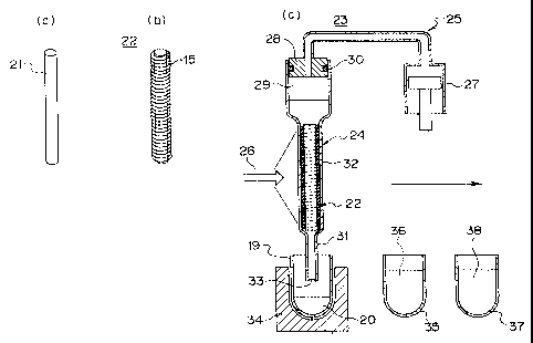
5 FIG. 1(a) shows a device for containing, reacting and measuring 10 according
to a
first embodiment.
The device for containing, reacting and measuring 10 according to this
embodiment has a transparent slender tube 11 serving as the container section
and having
a liquid inlet 12, a pump 13 connected to the slender tube 11 and serving as a
drawing and
10 discharging section for drawing and discharging liquid into and from the
slender tube 11,
and a light receiving and irradiating section 14 of a measuring device. Inside
the slender
tube 11 it is possible to contain a liquid, and a base member 15 immersed in
the liquid.
The base member 15 is formed in a long and slender shape, and detection
substances such as for example oligonucleotides having already known various
base
15 sequences are arranged so as to be lined up at predetermined spacing along
the
longitudinal direction thereof The base member 15 is contained inside the
slender tube 11
in an extended and secured condition so as to adhere to the slender tube 11.
Here,
reference symbol 16 shows where labeled bonding substances being target
substances,
bond to the substance for detection to thereby label fixed positions thereof.
By analyzing
20 these labeled fixed positions, the unknown chemical structure of the target
substance can
be determined.
The pump 13 has a tube 17 made from a resilient body and communicated with the
slender tube 11, a pressing section 18 for pressing and contracting the tube
17, and a
switching valve (not shown in the figure). The pump 13 draws and discharges
into and
from the slender tube 11, liquid 20 contained in a container 19 provided
external to the
device for containing, reacting and measuring 10. In the liquid 20 is
suspended a target
substance which has been labeled by a fluorescent substance or the like (not
shown in the
figure).
The light receiving and irradiating section 14 is one for shining an
excitation light
beam for exciting the fluorescent substance, and receiving the produced
fluorescence. A
scanning section (not shown in the figure) which is moved for scanning, is
provided along
the slender tube 11.
CA 02439169 2003-08-07
21
The shape and size of the slender tube 11 is detenmined based on the shape and
size of the base member 15, and is preferably a size and shape such that the
base member
15 can be easily contained inside the slender tube 11 with a margin, and so
that a gap
produced between the inner wall of the slender tube 11 and the surface of the
base
member 15 is small to the extent that the base member 15 is easily wetted with
a small
amount of liquid. As shown in FIG. 1(b), in order to satisfy this condition,
the size of the
diameter of the slender tube 11 is suitably approximately two times the size
of the width
or the diameter of the base member 15, and for example in the case where the
diameter of
the base member 15 is approximately 0.1 mm, then preferably the diameter of
the slender
tube 11 is for example approximately 0.2 mm.
Next, FIG. 2 shows a device for containing, reacting and measuring according
to a
second embodiment.
FIG. 2 (a) shows a core 21 serving as a rod shape or cylindrical shape carrier
for
carrying the aforementioned base member 15 wound around the surface thereof.
FIG. 2
(b) shows an integrated carrier 22 with the beforementioned base member 15
wound
thereon. Here the diameter of the core 21 is for example from approximately 2
to 4 mm,
while the thickness of the base member 15 is from approximately 0.05 mm to 0.2
nun, and
the length of the base member 15 is for example from approximately 500 mm to
3000 mm.
FIG. 2 (c) illustrates a device for containing, reacting and measuring 23, and
a method of
containing, reacting and measuring according to the second embodiment.
The device for containing, reacting and measuring 23 has a pipette section 24
serving as the container section, a drawing and discharging section 25 for
drawing and
discharging into and from the pipette section 24, and a light receiving and
irradiating
section 26 of the measuring device provided external to the pipette section
24. In the
drawing and discharging section 25 is provided a cylinder 27, and a nozzle
section 28
communicated with the cylinder 27 through a pipe.
The pipette section 24 has a mounting section 29 removably mounted on the
nozzle section 28 via an 0-ring 30, a small diameter section 31 having a
single inlet/outlet
33 at a tip end, and which is insertable into a container 19 external to the
device for
containing, reacting and measuring 23, and a large diameter section 32
provided between
the small diameter section 31 and the mounting section 29 and having a
diameter larger
than that of the small diameter section 31 for containing the integrated
carrier 22. The
CA 02439169 2008-02-05
22
opening of the mounting section 29 constitutes a container opening for
insertion and
accommodation of the integrated carrier 22.
The shape and size of the large diameter section 32 is determined by the shape
and
size of the integrated carrier 22. The size and shape of the large diameter
section 32 is a
size where the integrated carrier 22 can be easily contained inside the large
diameter
section 32 with a margin, and is preferably a size and shape so that a gap
produced
between the inner wall of the large diameter section 32 and the surface of the
base
member 15 of the integrated carrier 22 is small to the extent that the base
member 15 is
easily wetted with a small amount of liquid but does not adhere to the inner
wall of the
large diameter section 32. Here the amount of liquid is for example
approximately 100
liters.
The drawing and discharging section 25 is for drawing and discharging the
liquid
into and from the large diameter section 32 via the inlet/outlet 33.
Furthermore, with
this embodiment, while not shown in the figure, this has a moving mechanism
capable of
15 relatively moving the inlet/outlet 33 between externally provided
containers 19, 35 and 37.
Moreover, a light receiving and irradiating section 26 of the measuring device
is
one which uses for example an optical fiber for irradiating excitation light
and receiving
the fluorescence, being a movable device which can be scanned in the vertical
direction
external to the large diameter section 32 of the pipette section 24, and
rotated through 360
20 degrees around the large diameter section 32.
In the device for containing, reacting and measuring 23 according to this
embodiment, the pipette section 24 is removably mounted on the nozzle section
28.
Consequently, as well as the case of replacing the pipette section with
another pipette
section of the sarne construction which is mountable on the nozzle section 28,
a pipette
with a magnetic force device provided on the outside to thereby exert a
magnetic field so
that magnetic particles are adhered to the inner wall and can thus be
separated, may also
be removeably mounted.
Since by so doing, the magnetic particles can be separated, it is possible to
consistently perform processing for an even wider range also including for
example
extraction and separation of genetic material. Consequently, according to this
embodiment, by using in common the same drawing and discharging section,
various
CA 02439169 2003-08-07
23
types of processing using magnetic particles, and various types of processing
using base
members can be consistently and automatically performed.
Next is a description based on FIG. 2, of a method for determining base
sequences
for analysis of a bonding substance being the target substance, using the
device for
containing, reacting and measuring 23 according to this embodiment.
In FIG. 2 (c), at first in a step S 1, a liquid 20 in which is previously
suspended a
target substance comprising a DNA fragment for which an unknown base sequence
is to
be determined and which has been has been labeled with fluorescence, is placed
in the
container 19.
Furthermore, an integrated carrier 22 with the base member 15 with various
already known oligonucleotides with their base sequences and each of their
fixed positions
associated, wound around the core 21, is contained inside the large diameter
section 32 of
the pipette section 24 serving as the container section, and after this the
pipette section 24
is mounted on the nozzle section 28.
In step S1, a probe solution with a predetermined reagent mixed in a liquid in
which is suspended the target substance labeled with a fluorescent substance
or the like, is
pre-heated for a few minutes at approximately 95 C in a constant temperature
tank 34
provided with a Peltier element. Then the current direction is changed to
thereby cool the
solution in a condition where this is held at a normal temperature or a
different
temperature to normal if required, to adjust the solution to an easily
hybridized form. In
determining the unknown base sequence of the DNA fragment, needless to say as
a pre-
requisite, in addition to the hybridization process, a process for
denaturation of the DNA
fragment is necessary.
In step S2, the small diameter section 31 of the pipette section 24 is moved
to the
container 19 and inserted therein. The container 19 is held in the constant
temperature
tank 34 at normal temperature, or if required at a temperature different from
the normal
temperature, and incubation and reaction is performed over a few minutes to a
few hours.
In step S3, after completion of reaction, the small diameter section 31 of the
pipette section 24 is moved and inserted into the container 35 which contains
a first
cleaning solution 36 at room temperature, and this is then shaken and washed
so that
excess probe solution in which is suspended the target substance and the like
is removed.
In step S4, after the first washing, the small diameter section 31 of the
pipette
section 24 is moved and inserted into the container 37 which contains unused
second
CA 02439169 2008-02-05
24
cleaning solution 38, and this is again shaken and washed, and the remaining
probe
solution is removed.
In step S5, the light receiving and irradiating section 26 of the measuring
device
measures from outside of the integrated carrier for which washing is
completed, by
scanning the perimeter of the large diameter section 32 vertically and through
360 degrees
therearound with the scanning section.
Next, is a description of a device for containing, reacting and measuring 40
according to a third embodiment, based on FIG. 3.
FIG. 3 (a) shows the device for containing, reacting and measuring 40
according to
the third embodiment. This device for containing, reacting and measuring 40
uses another
integrated carrier 42. The integrated carrier 42, as shown in FIG. 3 (a) has
the base
member 15 wound around a core 41 as the carrier.
As shown in FIG. 3 (b), at opposite rims of the core 41 are respectively
provided
annular protruding portions 41 a serving as the protective portions. By means
of these
protective portions, the base member 15 is bound so as not to come off from
the core 41
being the carrier, and contact between an inner wall of a pipette section 44
serving as a
later mentioned container section and the base member 15 is prevented, so that
the liquid
passing the surface of the base member 15 flows smoothly, and the integrated
carrier 42 is
positioned inside the container section, thus enabling reliable measurement.
Consequently,
the core 41 is formed in an overall spool shape.
On these annular protruding portions 41 a are provided a plurality of cut out
portions 43 so that the liquid can pass therethrough, and the contact portions
at the tip of
the annular protruding portion 41 a which contact with the inner wall are
formed in a
wedge shape so that the contact area with the inner wall is minimal. As a
result, liquid
residue is prevented, and the process can be smoothly performed. The height of
the
annular protruding portions 41 a is made a height exceeding the thickness of
the wound
base member 15, to thereby prevent the base member 15 from touching or
adhering to the
inner wall.
Furthermore, instead of the annular protruding portions 41 a, protective
portions
142c as shown in FIG. 3 (b) may be provided. With these protective portions
142c, a
plurality of radially protruding portions 142a are provided, and the height of
these
protruding portions 142a is set so as to exceed the thickness of the base
member 15.
CA 02439169 2008-02-05
The device for containing, reacting and measuring 40 which uses the integrated
carrier 42, has a pipette section 44 serving as the container section, a
drawing and
discharging section 48 for performing drawing and discharging into and from
the pipette
section 44, and a linear light receiving and irradiating section 50 provided
external to the
5 pipette section 44. Reference symbol 48 denotes a nozzle section provided in
the drawing
and discharging section.
The linear light receiving and irradiating section 50 is attached to a rod
shape
support member with tip sections of a large number of optical fibers arranged
in a line.
Each of the fibers is connected to a photodetector and a light source for
irradiating
10 excitation light for exciting the fluorescent substances used in the
labeling. As a result,
the fluorescence excited thereby can be simultaneously received.
Furthermore, the linear light receiving and irradiating section 50 may be such
that
direct photodetectors are arranged in a line, and there is provided a light
source for
irradiating excitation light. This linear light receiving and irradiating
section 50 is
15 provided so as to be able to be turned through 360 degrees around the
periphery of the
large diameter section 45 by means of a scanning section (not shown in the
figure).
Furthermore, the mounting portion containing the pipette section 44 may be
provided so as
to be able to be rotated through 360 degrees around the axis of the pipette
section 44. This
linear light receiving and irradiating section 50 corresponds to the measuring
device.
20 The pipette section 44 has a removably mounted large diameter section 45
engaged
with the nozzle section 48 via an 0-ring 49, and which contains the integrated
carrier 42,
and a small diameter section 46 with a tip having an inlet/outlet 47, which
can be inserted
into a container external to the device for containing, reacting and measuring
40. Here the
diameter of the large diameter section 45 is for example an inner diameter of
25 approximately 4 nun. The opening of the large diameter section 45
constitutes the
container opening for insertion and accommodation of the integrated carrier.
Here the annular protruding portion 41 a of the integrated carrier 42 is
preferably
formed in a size to contact with the inner wall of the large diameter section
45. The
outside diameter of the integrated carrier 42 is for example approximately 3.8
mm.
FIG. 3 (c) and (d) shows a device for containing, reacting and measuring 51
according to a fourth embodiment. This device for containing, reacting and
measuring 51
uses an annular light receiving and irradiating section 52 as the measuring
device, instead
of the linear light receiving and irradiating section 50 formed in the linear
shape. To the
annular
CA 02439169 2003-08-07
26
light receiving and irradiating section 52 is fitted an annular support member
with tip
portions of a large number of optical fibers 53 arranged annularly. These
optical fibers 53
irradiate excitation light and at the same time receive fluorescence.
The other ends of the optical fibers 53 are connected to a line sensor 54
comprising
photodetectors arranged in a line. Furthermore, the other ends of the optical
fibers 53 may
be connected to a planar CCD element. Moreover, this annular light receiving
and
irradiating section 52 is provided so as to be moveable vertically by means of
a scanning
section (not shown in the figure). Moreover, an equipment part including the
pipette
section 44 may be provided so as to be moveable vertically by means of the
scanning
section.
FIG. 4 shows one example of a measured identification pattern 55 with fixed
positions, and qualitative and quantitative information for the fixed
positions displayed as
a plain surface. Here reference symbol 56 denotes positions on an image of the
base
member 15. Reference symbol 57 denotes reference points which are labeled
beforehand
so as to become references for specifying fixed positions of the base member
15.
Reference symbol 58 shows fixed positions where the labeled target substance
has been
bonded. According to this example, the measurement results for each of the
labeled fixed
positions may be processed as planar information.
Next is a description of a device for containing, reacting and measuring 60
according to a fifth embodiment, based on FIG. 5. As shown in FIG. 5 (a) and
(b), the
device for containing, reacting and measuring 60 according to this embodiment
has; a
pipette section 64 serving as the container section, a drawing and discharging
section 65
for drawing and discharging into and from the pipette section 64, and a light
receiving and
irradiating section 66 provided external to the pipette section 64. In the
drawing and
discharging section 65 is provided a cylinder 67, and a nozzle section 68
communicated
with the cylinder 67 through a pipe.
The pipette section 64 has a removably mounted mounting section 69 engaged
with the nozzle section 68 via an 0-ring 70, a small diameter section 71 with
a tip having
an inlet/outlet 73, and which is insertable into a container external to the
device for
containing, reacting and measuring 60, and a large diameter section 72
provided between
the small diameter section 71 and the mounting section 69 and having a
diameter larger
than that of the small diameter section 71 for containing an integrated
carrier 62.
CA 02439169 2008-02-05
27
The integrated carrier 62 is one where the base member 15 is wound around a
core
61. At opposite ends of the core 61 are respectively provided annular
protruding portions
61 a serving as the protective portions for protecting so that the base member
15 does not
come off from the core 61 and the base member 15 does not contact with the
inner wall,
and for ensuring smooth flow of the liquid, and for positioning. The core 61
is formed
overall in a spool shape, and on these annular protruding portions 61 a are
provided a
plurality of cut out portions 63 so that the liquid can pass therethrough.
Here the annular protruding portions 61 a of the integrated carrier 62 are
preferably
formed in a size so as to contact with the inner wall of the large diameter
section 72.
The drawing and discharging section 65 is for drawing and discharging the
liquid
into and from the large diameter section 72 via the inlet/outlet 73.
Furthermore this
embodiment, while not shown in the figure, has a moving mechanism which can
relatively
move the inlet/outlet 73 between various processing areas and processing
positions such
as externally provided containers, and a later described light shielding box
74.
With this embodiment, the light receiving and irradiating section 66 of the
measuring device is provided in the light shielding box 74. The light
shielding box 74 is
used for shutting off noise of excess light generated from the exterior or
from the interior
at the time of measuring the fluorescence generated by the integrated carrier
62. The light
shielding box 74 has a box body 75 provided with the light receiving and
irradiating
section 66 of the measuring device and with the pipette section 64 inserted
thereinside,
and a cover 76 provided on an opening of the box body 75. An aperture 77 is
formed in a
central portion of the cover 76 for enabling insertion of the pipette section
64. Moreover,
around the periphery of the aperture 77 a double annular wall section 78 is
provided
upwardly protruding so as to form an annular groove therebetween.
On the other hand, an annular cover plate 79 for covering the aperture 77 is
provided so as to protrude sideways from the surroundings of the upper portion
of the
nozzle section 68. On a lower side of the cover plate 79 provided so as to
protrude
downwards, is an annular protrusion 80 for insertion into the groove formed by
the double
annular wall 78 to form an enclosed space thereinside. Here the cover plate
79, the double
annular wall 78 and the annular protrusion 80 correspond to a closure device.
Furthermore, with the device for containing, reacting and measuring 60
according
to this embodiment, there is provided a rotation section (not shown in the
figure) serving
as the scanning section, which can scan the whole periphery of a part
containing the
CA 02439169 2003-08-07
28
pipette section 64, in relation to the central axis of the pipette section 64.
By rotation by
this rotation section, the annular protrusion 80 slides inside the groove
formed in the
double annular wall section 78. As a result, complete light shielding is
achieved, and all
of the fixed positions provided on the integrated carrier 62 contained inside
the large
diameter section 72 can be scanned and the light received without any leakage.
FIG. 5 (a) shows the condition where the pipette section 64 is being moved
downward by the moving section (not shown in the figure) in order to insert
the pipette
section 64 inside the light shielding box 74, while FIG. 5 (b) shows the
condition where
insertion of the pipette section 64 into the light shielding box 74 has been
completed, and
measurement is being performed.
The measuring device parts other than the light receiving and irradiating
section 66
may be provided inside the light shielding box 74 or outside. In the case of
the latter, the
light shielding box 74 can be made smaller.
Next is a description of a device for containing, reacting and measuring 81
according to a sixth embodiment, based on FIG. 6.
The device for containing, reacting and measuring 81 according to this
embodiment, as shown in FIG. 6 (a) and (b) has; a pipette section 85 serving
as the
container section, a drawing and discharging section 86 for drawing and
discharging into
and from the pipette section 85, and a light receiving and irradiating section
87 provided
external to the pipette section 85. In the drawing and discharging section 86
is provided a
cylinder 88, and a nozzle section 89 communicated with the cylinder 88 through
a pipe.
The pipette section 85 has a removably mounted mounting section 90 engaged
with the nozzle section 89 via an 0-ring 91, a small diameter section 92 with
a tip having
an inlet/outlet 93, and which is insertable in a container 19 external to the
device for
containing, reacting and measuring 81, and a large diameter section 94
provided between
the small diameter section 92 and the mounting section 90 and having a
diameter larger
than that of the small diameter section 92 for containing an integrated
carrier 82. The
opening of the large diameter section 94 constitutes the container opening for
insertion
and accommodation of the integrated carrier.
The integrated carrier 82 has a region 84 where this is wound as a spiral
within a
plane on the core 83 being the center of the base member 15, and is different
from the
aforementioned integrated carriers 42 and 62 where the base member 15 is wound
in one
layer only in a cylindrical shape.
CA 02439169 2008-02-05
29
Furthermore, in the device for containing, reacting and measuring 81 according
to
this embodiment, a cylindrical external screw section 96 is provided beneath
the mounting
section 90 with a thread 98 provided on an external surface thereof. On the
other hand, a
cylindrical recess screw section 95 is provided on an upper portion of the
large diameter
section 94, with a screw thread 97 provided on an internal surface thereof.
Moreover, an
0-ring 99 is provided between the external screw section 96 and the recess
screw section
95 to give high water tightness.
As a result, with this embodiment, the integrated carrier 82 which has a
greater
diameter than the mounting section 90 can be easily accommodated by
unfastening the
external screw section 96 from the recess screw section 95. A pipe 99a of a
predetermined
length may be provided so as to protrude from the lower side of the external
screw section
96 to prevent lifting of the integrated carrier 82, and enable the integrated
carrier 82 to be
accommodated and fixed in a predetermined position.
Furthermore, instead of the case where, as described above, the large diameter
section and the mounting section are provided so as to be able to be opened
and closed by
means of the screw sections so that the base member (or the DNA chip or the
integrated
carrier) is provided so as to be able to be accommodated or taken out, after
accommodating the base member in the large diameter section, this may be
sealed in by
welding with ultrasonic welding or the like between the mounting section and
the large
diameter section. In this case, since from the start the base member is
accommodated
inside the container section, then the reliable prevention of cross-
contamination is possible.
FIG. 7 shows a containing, reacting and measuring device 100 according to a
seventh embodiment.
The containing, reacting and measuring device 100 according to this embodiment
has; a pipette section 101 serving as the container section, a drawing and
discharging
section for performing drawing and discharging with respect to the pipette
section 101,
and a measuring device provided on the outside of the pipette section 101
capable of
receiving light from the pipette section 101 in a condition associated with
the light
emission position.
The pipette section 101 has a mounting section 104 removably mounted on the
nozzle section 103 of the drawing and discharging section via an 0-ring, a
small diameter
section 106 having a single inlet/outlet 105 at a tip end, and which is
insertable into a
container external to the device for containing, reacting and measuring 100,
and a
CA 02439169 2003-08-07
transparent large diameter section 108 capable of containing the integrated
carrier 107,
provided between the small diameter section 106 and the mounting section 104
and having
a diameter larger than that of the small diameter section 106.
The opening of the mounting section 104 constitutes a container opening for
5 inserting and containing the integrated carrier 107 in the large diameter
section 108.
The shape and size of the large diameter section 108 is determined by the
shape
and size of the integrated carrier 107. The size and shape of the large
diameter section
108 is a size where the integrated carrier 107 can be easily contained inside
the large
diameter section 108 with a margin, and is preferably a size and shape so that
a gap
10 produced between the inner wall of the large diameter section 108 and the
surface of the
integrated carrier 107 is small to the extent that the integrated carrier 107
is easily wetted
with a small amount of liquid but the surface thereof does not adhere to the
inner wall of
the large diameter section 108. Here the amount of liquid is for example
approximately
100 liters.
15 The drawing and discharging section is for drawing and discharging the
liquid into
and from the large diameter section 108 via the inlet/outlet 105. Furthermore,
with this
embodiment, while not shown in the figure, this has a moving mechanism capable
of
relatively moving the inlet/outlet 105 between externally provided containers.
Moreover, the integrated carrier 107 contained inside the pipette section 101
is one
20 where a base member 110 on which various kinds of substances for detection
109 are
fixed at respective fixed positions arranged in a spaced apart condition, is
wound on a
cylindrical core (not shown in the figure). The integrated carrier 107 has
annular
protruding portions 111 and 112 on the upper end and lower end of the carrier,
which have
a plurality of cutout portions 111 a and 112a, and which have a shape to fit
tightly against
25 the inner wall of the large diameter section 108, and is fixed inside the
large diameter
section 108 by means of these. The cutout portions 111a and 112a are for
allowing liquid
to pass in the vertical direction. As a result, the integrated carrier 107 is
fixed and
contained inside the large diameter section 108 in a condition immersed in the
liquid.
Reference symbol 113 denotes an 0-ring provided between the nozzle section 103
30 and the mounting section 104 for maintaining water tightness.
The integrated carrier 107 is one where various kinds of substances for
detection
109, for example oligonucleotides having already known various base sequences,
are
arranged and fixed in a spaced apart condition, and has a base member 110
formed in a
CA 02439169 2008-02-05
31
long and slender shape such as a filament, a braid, or tape with various
substances for
detection 109 and their fixed positions associated, and a core being a carrier
on which the
base member 110 is wound. The substances for detection 109 are ones which show
that,
by bonding with a bonding substance being a labeled target substance, their
fixed position
are identified. By analyzing these labeled fixed positions, the unknown
chemical structure
of the target substance can be determined.
The drawing and discharging section has, in addition to the nozzle section
103, a
pump or the like (not shown in the figure) which communicates with the nozzle
section
103.
The measuring device has a measuring device body 102 having an irradiating
section 114 for irradiating an excitation light beam for exciting the
fluorescent substance,
and a light receiving section 115 for receiving fluorescent light excited by
the irradiation,
and a scanning section (not shown in the figure) for rotationally driving the
nozzle section
103 to scan the integrated carrier 107.
The irradiating section 114 has an optical fiber bundle 116 having a large
number
of optical fibers, a light source 117 for generating a trigger beam, and an
optical fiber
support section 119 which supports the optical fiber tip portions 118 arranged
close to the
outer face of the large diameter section 108, in column form along the axial
direction of
the nozzle section 103 and hence the pipette section 101. The layout of the
tip portions of
the optical fibers, is for example an array in matrix form of ten columns by
300 rows.
Furthermore, the tip portions of the optical fibers may be given a lens
function.
The light receiving section 115 has an optical fiber bundle 120 having a large
number of optical fibers, an optical fiber support section 122 which supports
the tip
portions 121 of the optical fibers arranged close to the outer face of the
large diameter
section 108, in column form along the axial direction of the nozzle section
103 and hence
the pipette section 101, and a light receiving device 123 comprising a line
shape optical
sensor or CCD camera provided on the other end side of the optical fiber
bundle 121.
FIG. 8 (a) shows in detail the positional relationship between the pipette
section
101 and the measuring device body 102 shown in FIG. 7. As shown in this
figure, the tip
portion 118 of the optical fiber bundle 116 is arranged across the whole of
the integrated
carrier 107 contained in the large diameter section 108. Furthermore, FIG. 8
(b) shows an
irradiating section 124 according to another example. The irradiating section
124, instead
of using the optical fiber bundle uses fiberglass 125. By illuminating the
rear side face of
CA 02439169 2003-08-07
32
the fiber glass 125 with a light source 126, a uniform light can be shone onto
the
integrated carrier 107 contained in the large diameter section 108.
FIG. 9 (a) shows in detail the positional relationship between the pipette
section
101 and the light receiving section 115 shown in FIG. 7. As shown in this
figure, the tip
portion 121 of the optical fiber bundle 120, is arranged across the whole
length of the
integrated carrier 107 contained in the large diameter section 108. Here,
reference symbol
127 denotes a line sensor for sensing light. Instead of providing the line
sensor 127, a
CCD camera may be provided.
FIG. 9 (b) shows a light receiving section 128 according to another example.
The
light receiving section 128 comprises a vapor deposition layer 129 as a
filter, a fixed glass
layer 130 for performing adjustment of the focus, fiber glass 131, and a CCD
camera or
line sensor 132.
FIG. 10 shows a pipette section according to an eighth embodiment.
The pipette section 133 shown in FIG. 10 (a), as with the aforementioned
pipette
section 101, has a mounting section 134 which is removably mounted on the
nozzle
section via an 0-ring, a small diameter portion 136 having one inlet/outlet
135 on the tip
end, and capable of insertion into a container outside of the containing,
reacting and
measuring device, and a transparent large diameter section 137 provided
between the
small diameter section 136 and the mounting section 134, having a diameter
which is
larger than that of the small diameter section 136, and capable of containing
the integrated
carrier. On the outside face of the large diameter section 137 there is
provided a plurality
of cylindrical lenses 138 having generatrix parallel with the axial direction.
The
cylindrical lenses 138 do not have a refractive effect in a plane containing
the generatrix,
but have a similar refractive effect to a normal lens in a plane perpendicular
to the
generatrix.
FIG. 10 (b) shows another example of a pipette section 139 according to the
eighth
embodiment. The pipette section 139, excluding the large diameter section 140
is the
same as the pipette section 133. In the large diameter section 140 on the
inside face
thereof is provided a large number of cylindrical lenses 141 having generatrix
parallel
with the axial direction. The cylindrical lenses 141 do not have a refractive
effect in a
plane containing the generatrix, but have a similar refractive effect to a
normal lens in a
plane perpendicular to the generatrix.
CA 02439169 2008-02-05
33
FIG. 11 (a) shows the positional relationship between the pipette section 101
of the
containing, reacting and measuring device 100 and the irradiating section 114
and light
receiving section 115 of the measuring device body 102. Here, reference symbol
142
denotes a core of the integrated carrier 107. The pipette section 101 is
capable of
translational movement along the X-axis, Y-axis and Z-axis directions with
respect to the
measuring device body 102, and when carrying out measurement, by
translationally
moving this in a semicircular shape groove section 102a of the measuring
device body 102
arranged with the tip portions of the irradiating section 114 and the light
receiving section
115, these are positioned at the side face of the integrated carrier 107
contained in the
large diameter section 108. Then, by rotating the nozzle section 103, the
fixed positions
and qualitative and quantitative information of the fixed positions can be
obtained. If
these measurement results are displayed on a plain surface, then for example
this gives the
image 143 as shown in FIG. 11 (b). Such an image 143 may be displayed on a
display
section as an output section connected to the measuring device body 102 (not
shown in the
figure) or printed out or stored in a storage section. By measuring the light
emission
position being the image 143, then structure and the like of the target
substance can be
analyzed. Here, reference symbol 109a denotes marks due for example to a light
emission
substance, used for identifying the fixed position. This mark is set so as to
also represent
the standard strength of the quantitative information.
Next is a description of a containing, reacting and measuring device 144
according
to a ninth embodiment based on FIG. 12. The containing, reacting and measuring
device
144, as shown in the figure, has as the illumination section, a laser device
145 serving as
an illumination section which outputs a line shape beam having lines along the
longitudinal direction (the direction perpendicular to the paper in FIG. 12)
along an axial
direction of the large diameter section 108 of the pipette section 101, and
the laser beam
irradiated from the laser device 145 passes through a filter 146 for removing
wavelengths
other than of the necessary excitation light for exciting the fluorescent
substance. Then,
by means of a semicylinder type cylindrical lens 147, this is converged in a
planar
direction (transverse direction) parallel to the paper, and by means of half
mirrors 148 and
149, a laser beam having a predetermined length in the vertical direction is
irradiated onto
the integrated carrier 107 contained inside the large diameter sectiori 108.
The light in a
line shape containing fluorescence and having a predetermined length in the
longitudinal
direction which is generated by the irradiated laser light, passes through the
half mirror
CA 02439169 2008-02-05
34
149 and by means of a cylindrical lens 150, is made parallel light, and passes
through a
filter 151, and is then converged in the transverse direction by a cylindrical
lens 152, and
is received by a light receiving section 153.
Next is a detailed description of a device for containing, reacting and
measuring
155 having a pipette section being a multi set (in this example six sets)
container section,
according to a tenth embodiment, based on FIGS. 13, 14, 15 and 16.
As shown from the front face in FIG. 13, the device for containing, reacting
and
measuring 155 according to this embodiment has; six sets of pipette sections
156, six sets
of rotatably provided nozzle sections 157 on which the pipette sections 156
are mounted,
and a drawing and discharging section 159 which performs drawing and
discharging of a
liquid with respect to the six sets of pipette sections 156, by adjusting the
pressure thereof
with respect to the six sets of pipette sections 156, via six sets of circular
tubes 156.
The pipette section 156 has a mounting section 160 removably mounted on the
nozzle section 157, a small diameter section 162 having a single inlet/outlet
161 at a tip
end, and which is insertable into a container (not shown) external to the
device for
containing, reacting and measuring 155, and a large diameter section 163
provided
between the small diameter section 162 and the mounting section 160 and having
a
diameter larger than that of the small diameter section 162.
Furthermore, the drawing and discharging section 159 has a cylinder block 164a
having six sets of cylinders which are communicated with the six sets of
nozzle sections
157 via the six sets of circular tubes 158, a ball screw 165 connected to
cylinder rods
(pistons) 164 inside the cylinder block 164a, which slides the six sets of
cylinder rods 164
altogether in the vertical direction, and a motor 167 for rotationally driving
the ball screw
165 via a coupler 166. Here reference symbol 168 denotes a section
corresponding to the
scanning section of the measuring device which contains the rotation mechanism
which
rotates the nozzle section 157.
FIG. 14 shows a sectional view from the side of the device for containing,
reacting
and measuring 155 shown in FIG. 13. In the scanning section 168, a belt 171
with teeth
on one side for transmitting rotation from a toothed pulley 169 provided on a
rotation shaft
of a later mentioned motor 177 contained in a motor containing section 170, to
the nozzle
section 157, is spanned between the toothed pulley 169 and a toothed pulley
172 provided
on the nozzle section 157. The whole of the nozzle section 157 can be rotated
by the
rotation mechanism, and is supported on a frame 175 so as to be moveable by a
CA 02439169 2003-08-07
predetermined distance d in the vertical direction. However, this is always
urged
downwards by means of a spring member 174 provided between an upper end 173 of
the
nozzle section 157 and the frame 175. Reference symbol 176 denotes an optical
sensor.
When the inlet/outlet 161 on the tip end of the pipette section 156 mounted on
the nozzle
5 section 157 receives a force due to contact with an external object, the
whole of the nozzle
section 157 is moved upwards, and a shielding section 173a provided on the top
end
section 173 thereof blocks off a photodetector 176a of the optical sensor 176,
so that the
grounding of the tip end of the pipette sections 156 can be detected. Here,
reference
symbol 177 denotes a rotation mechanism containing section for containing the
rotation
10 mechanism of the scanning section 168.
FIG. 15 shows the interior of the rotation mechanism containing section 177.
In
this example, the driving force of the motor 178 contained inside the motor
containing
section 170 is transmitted to the nozzle section 157 by means of the belt
mechanism. The
toothed pulley 169 is provided on the rotation shaft of the motor 178. The
belt 171 is
15 spanned between the toothed pulley 169, and the toothed pulleys 172
provided on the six
sets of nozzle sections 157, via seven rollers 179 and two toothed pulleys
180. The
rotation mechanism may be constructed by a combination of gears instead of the
belt
mechanism.
FIG. 16 shows in detail a section of the upper end portion 173 of the nozzle
section
20 157. The upper end region 173 has a tip portion 182 having a rim protruding
radially from
the nozzle section 157, a transverse cavity 184 extending in the transverse
direction and
communicated with a longitudinal cavity 183 extending in the longitudinal
direction inside
the nozzle section 157, and an annular groove 185 provided annularly around
the
periphery passing an opening section of the transverse cavity 184. This
annular groove
25 185 is provided in order to smoothly pass air from the cylinder 164 through
the circular
tube 158. At the upper end portion 173 of the nozzle section 157, the outer
diameter of
the nozzle section 157 is formed slightly thinner than the outer diameter of
the other
regions, and is rotatably supported with respect to the circular tube support
section 189
which supports the circular tube 158, via bearings 187 and 188. Here the
circular tube
30 support section 189 does not rotate with rotation of the nozzle section
157, but moves with
movement of the nozzle section 157 in the vertical direction. Reference
symbols 190 and
191 denote 0-rings.
Next is a description of the operation of the device according to the
embodiments.
CA 02439169 2003-08-07
36
In the six sets of pipette sections 156, there is respectively contained
integrated
carriers (not shown in the figure). The device for containing, reacting and
measuring 155
including the pipette sections 156 can be moved as a whole in the X, Y and Z
axis
directions. This is moved to a plurality of containers which contain a
predetermined
reagent, and the small diameter portions 162 of the pipette sections 156 are
inserted into
the containers. Then for the liquid such as the contained reagent, drawing and
discharging
of the liquid via the inlet/outlet 161 is performed by rotating the motor 167
of the drawing
and discharging section 159 to rotate the ball screw 155 via the coupler 166,
to vertically
move the cylinder rods 164 contained inside the cylinder block 164a and
attached to the
nut section threaded onto the ball screw 165, so that air flows into and is
discharged from
the pipette sections 156 through the circular tube 158, the transverse cavity
184, the
annular groove 185 and the longitudinal cavity 183. By so doing, the
integrated carrier
and the liquid contained in the large diameter section 163 are brought into
contact to
perform the reaction process. When the small diameter portion 162 is inserted
into the
container, the inlet/outlet 161 contacts the bottom of the container, and when
the pipette
section 156, and hence the nozzle section 157 mounted on the pipette section
156 moves
the small distance d, the grounding is detected by the grounding sensor 176,
so that
movement in the downward direction by the moving section is stopped, and the
drawing
/discharging operation is then performed.
When the necessary processing has been completed, and measuring is performed
taking the light emission due to the fluorescent substance being the target
substance,
which is produced by the integrated carrier, the pipette section 156 of the
device for
containing, reacting and measuring 155 is moved as far as the predetermined
position of
the light receiving section and the irradiating section of the measuring
device body, and
scanning for measurement is performed by the scanning section 168 by rotating
and
driving the nozzle section 157. Scanning by means of this scanning section 168
involves
rotationally driving the motor 178 to rotate the toothed pulley 169 provided
on the rotation
shaft of the motor 178, and thus rotationally drive each of the six sets of
respective nozzle
sections 157 by means of the belt 171 spanned between the toothed pulley 169
and the
toothed pulleys 172 and the like. At the same time, the excitation light from
the
irradiating section is irradiated onto the integrated carrier and the
generated fluorescence
is measured.
CA 02439169 2003-08-07
37
The above described respective embodiments have been described in detail to
further explain the present invention, and in no way preclude other
embodiments.
Consequently the embodiments can be altered provided the gist of the invention
is retained.
For example, with each of the embodiments, the description was only for the
case where
oligonucleotides were used as the detection substance. However the invention
is not
limited to this case, and for example not only other genetic material but also
immunity
substances, amino acids, proteins, sugars and so forth may be used.
Furthermore, in the
first embodiment, the description was for the case where a pump was used as
the drawing
and discharging section. However the invention is not limited to this case,
and for
example this may comprise a cylinder and piston.
Moreover, in the above description, the case where fluorescence was measured
as
the measurement device was described. However the case of chemiluminescence,
or
measurement of electromagnetic waves of various wavelengths is also possible.
For
example, the case of measuring wavelength ranges of electromagnetic waves of
for
example infrared rays, ultraviolet rays, X-rays, radio waves and so forth
outside of the
visual light, as the electromagnetic waves is also possible.
Furthermore, in the above description, only the case where each pipette
section or
slender tube was one set was described. However the invention is not limited
to this case,
and for example a case where another set of pipette sections or slender tubes
are provided
in rows is also possible. Moreover, needless to say, the numerical values used
in the
above description are only for example, and are not limiting to the invention.
Furthermore,
the various components constituting the device for containing, reacting and
measuring
described in the various embodiments may be optionally selected and suitably
modified
and combined to thereby make up new apparatus for containing, reacting and
measuring.
The laser beam from the laser device may be irradiated so as to scan the
integrated carrier
in the longitudinal direction using a polygon mirror, and then be received.
Furthermore, by providing two light receiving sections for receiving light
from
different directions at different positions, on the measuring device body,
stereoscopic
vision is possible. As a result, the fixed positions can be made three
dimensional.
Therefore a high density integrated carrier which is integrated in multi
layers can also be
measured more accurately. In this case, due to the distance between the
respective light
receiving sections, and the angle of the measuring direction of the respective
light
CA 02439169 2003-08-07
38
receiving sections, it is possible to detect differences in the distance in
the depth direction
thereof.
Moreover, in the case of measuring by rotating the container section, then as
a
measurement positioning section for preventing rotation swing, for example a
guide
member for guiding the rotation may be provided near the measurement position,
for
example in the groove section 102a, so as to contact the outer peripheral face
of the
container section (pipette section), for example the outer peripheral face of
the large
diameter section or the small diameter section, at one place, or so as to
contact between a
plurality of places, or to contact the whole periphery. Furthermore, a
mechanism may be
provided coupled to the container section itself, for rotationally driving the
container
section.