Sélection de la langue

Search

Sommaire du brevet 2439417 

Énoncé de désistement de responsabilité concernant l'information provenant de tiers

Une partie des informations de ce site Web a été fournie par des sources externes. Le gouvernement du Canada n'assume aucune responsabilité concernant la précision, l'actualité ou la fiabilité des informations fournies par les sources externes. Les utilisateurs qui désirent employer cette information devraient consulter directement la source des informations. Le contenu fourni par les sources externes n'est pas assujetti aux exigences sur les langues officielles, la protection des renseignements personnels et l'accessibilité.

Disponibilité de l'Abrégé et des Revendications

L'apparition de différences dans le texte et l'image des Revendications et de l'Abrégé dépend du moment auquel le document est publié. Les textes des Revendications et de l'Abrégé sont affichés :

  • lorsque la demande peut être examinée par le public;
  • lorsque le brevet est émis (délivrance).
(12) Demande de brevet: (11) CA 2439417
(54) Titre français: BOBINE DE STOCKAGE DE CABLE
(54) Titre anglais: CABLE STORAGE SPOOL
Statut: Réputée abandonnée et au-delà du délai pour le rétablissement - en attente de la réponse à l’avis de communication rejetée
Données bibliographiques
(51) Classification internationale des brevets (CIB):
  • G02B 06/44 (2006.01)
(72) Inventeurs :
  • HOLMAN, JOHN C. (Etats-Unis d'Amérique)
  • SMITH, TREVOR D. (Etats-Unis d'Amérique)
  • TINUCCI, THOMAS C. (Etats-Unis d'Amérique)
(73) Titulaires :
  • ADC TELECOMMUNICATIONS, INC.
(71) Demandeurs :
  • ADC TELECOMMUNICATIONS, INC. (Etats-Unis d'Amérique)
(74) Agent: ROBIC AGENCE PI S.E.C./ROBIC IP AGENCY LP
(74) Co-agent:
(45) Délivré:
(86) Date de dépôt PCT: 2002-03-05
(87) Mise à la disponibilité du public: 2002-09-19
Licence disponible: S.O.
Cédé au domaine public: S.O.
(25) Langue des documents déposés: Anglais

Traité de coopération en matière de brevets (PCT): Oui
(86) Numéro de la demande PCT: PCT/US2002/006845
(87) Numéro de publication internationale PCT: US2002006845
(85) Entrée nationale: 2003-08-25

(30) Données de priorité de la demande:
Numéro de la demande Pays / territoire Date
09/801,573 (Etats-Unis d'Amérique) 2001-03-07

Abrégés

Abrégé français

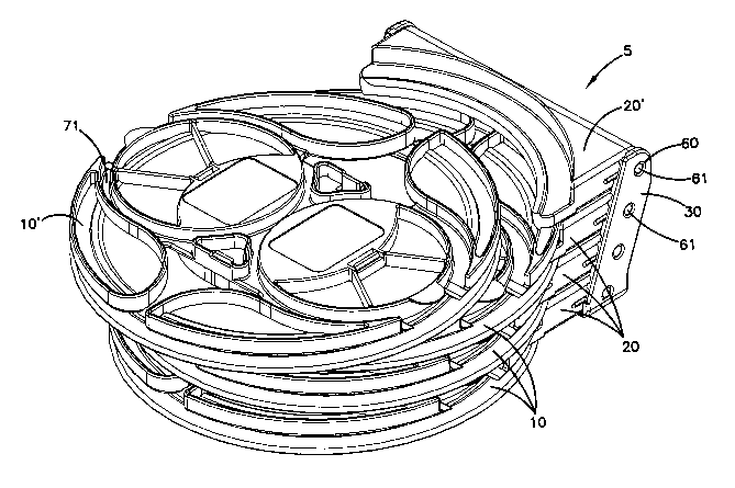
La présente invention concerne un ensemble de stockage de câble, permettant de stocker une longueur excessive de câble. Cet ensemble comprend une bobine à câble (10), un support de bobine (20) et une monture pour support (30). Ladite bobine à câble présente deux éléments de rebord (70, 80), qui sont couplés au moyen d'un montant central (50) et forment conjointement une enceinte de stockage de câble apparente (110). Un premier élément de rebord (70) comprend des éléments de limitation (71) de rayon et une ouverture de transition. La bobine reçoit un bras de support courbe du support de bobine, à l'intérieur de l'enceinte de stockage de câble (110). La bobine est retenue, de manière amovible, sur le support de bobine au moyen de rainures de retenue (76, 86) et de lèvres de retenue (26, 27) situées dans les rebords et sur le bras de support. Le montant central de la bobine peut être caractérisé par deux rayons (97, 98, 99) de courbure différents. Le support de bobine est monté pivotant sur la monture pour support. La monture pour support présente plusieurs emplacements de montage qui permettent un empilement en quinconce de bobines et de supports de bobine. Les supports de bobine et les montures pour support peuvent également présenter des pattes et des crans d'arrêt (33, 34).


Abrégé anglais


A cable storage assembly for storing an excess lenght of cable.The assembly
includes a cable spool (10), spool holder (20), and holder mount (30). The
cable spool has two flange members (70, 80) coupled by a center post (50),
together forming an exposed cable storage chamber (110). A first flange member
(70) includes radius limiting elements (71) and a transititon opening. The
spool receives a curved support arm of the spool holder into the cable storage
chamber (110). The spool is removably retained on the spool holder by means of
retaining grooves (76, 86) and retaining lips (26, 27) in the flanges and on
the support arm. The center post of the spool may be characterized by two
different radii (97, 98, 99) of curvature. The spool holder is pivotally
mounted in the holder mount. The holder mounts define a plurality of mounting
locations which allow for a staggered stack of spools and spool holders. The
spool holders and holder mounts may also include detent tabs and notches (33,
34).

Revendications

Note : Les revendications sont présentées dans la langue officielle dans laquelle elles ont été soumises.


What is claimed is:
1. A cable storage spool for storing an excess length of cable, the spool
comprising:
a first flange member having a first side and a second side, the first side of
the first flange member defining a loop channel for holding a loop end of the
cable in a fixed position relative to the first flange member, the first
flange
member defining at least one transition opening, the second side of the first
flange member defining a first retention groove;
a second flange member having a first side and a second side, the first side
of
the second flange member defining a second retention groove;
a center post coupling the second side of the first flange member to the first
side of the second flange member;
wherein the second side of the first flange member, the first side of the
second flange member and the center post define a cable storage chamber
wherein a
length of cable to be stored may pass from the loop channel of the first
flange
member through the transition opening of the first flange member to the
storage
chamber and may be wound around the center post;
and further wherein both the first and second flange have an outermost edge,
and wherein the first and second flange are spaced apart so that a spool
holder may
be received between the outermost edge of the first flange member and the
outermost edge of the second flange member and retained by the first and
second
retention grooves.
2. The cable storage spool of claim 1 wherein the center post includes a first
portion, a second portion, and a third portion, the first portion of the
center post
having a first radius of curvature, the second portion of the center post
having a
second radius of curvature different than the first radius of curvature, the
third
portion of the center post being straight.
9

3. The cable storage spool of claim 1 wherein the loop channel is defined by
first and second circular members and curvilinear walls opposing the circular
members, and wherein the loop channel includes a first channel portion and a
second channel portion, the first channel portion being defined by the first
circular
member and a first curvilinear wall, the second channel portion being defined
by the
second circular member and a second curvilinear wall, wherein the first
circular
member is spaced from the first curvilinear wall so that the first channel
portion is
sized to receive only one portion of the length of cable, and wherein the
second
circular member is spaced from the second curvilinear wall so that the second
channel portion is sized to receive two portions of the length of cable.
4. A cable spool holder for holding a cable storage spool, the holder
comprising:
a support body having a distal edge and two side surfaces, the distal edge of
the support body being curved,
a support arm extending from the distal edge of the support body, the support
arm being curved and having a first side and a second side, the support arm
including a first retaining lip on the first side of the support arm and a
second
retaining lip on the second side of the support arm wherein the support arm is
sized
to be received into a portion of an annular chamber of a cable storage spool.
5. The cable spool holder of claim 4 wherein the side surfaces of the support
body each include one of a pivot post and a pivot hole for receiving a pivot
post so
that the cable spool holder may be pivotally mounted to a rack.
6. The cable spool holder of claim 5 wherein the side surfaces of the support
body each include one of a detent tab or a detent notch.
7. A cable spool assembly for storing an excess length of cable, the spool
assembly comprising:
a cable spool having:
10

a first flange member having a first side and a second side, the first
side of the first flange member defining a loop channel for holding a loop
end of the cable in a fixed position relative to the first flange member, the
first flange member defining at least one transition opening;
a second flange member having a first side and a second side, at least
one of the first and second flange members defining a first retention member;
a center post coupling the second side of the first flange member to
the first side of the second flange member;
wherein the second side of the first flange member, the first side of
the second flange member, and the center post define a cable storage
chamber wherein a length of cable to be stored may pass from the loop
channel of the first flange member through the transition opening of the first
flange member to the storage chamber and may be wound around the center
post; and
a cable spool holder having:
a support body having a distal edge and two side surfaces, the distal
edge of the support body being curved;
a support arm extending from the distal edge of the support body, the
support arm being curved and having a first side and a second side, the
support arm including a second retention member on the support arm;
wherein the support arm of the cable spool holder is received in the cable
storage
chamber of the cable spool so that the first and second retention members of
the
cable spool and support arm, respectively, engage one another to selectively
hold the
cable spool to the cable spool holder.
8. The cable spool assembly of claim 7 wherein the center post of the cable
spool includes a first portion, a second portion, and a third portion, the
first portion
of the center post having a first radius of curvature, the second portion of
the center
post having a second radius of curvature different than the first radius of
curvature,
the third portion of the center post being straight.
11

9. The cable spool assembly of claim 7 wherein the side surfaces of the cable
spool holder each include one of a pivot post and a pivot hole for receiving a
pivot
post so that the cable spool holder may be pivotally mounted to a rack.
10. The cable spool assembly of claim 9, further comprising:
a cable holder mount having a plurality of pairs of opposed, staggered
mounting locations wherein a plurality of cable holders may be pivotally
mounted to
the cable holder mount to form a staggered stack of pivotable cable holders.
11. The cable spool assembly of claim 10, further comprising a chassis for
holding the cable holder mount.
12. The cable spool assembly of claim 10 wherein the cable holder mount
includes one of a detent tab and a detent notch to engage the respective
detent tab or
detent notch of the cable holder.
13. A cable storage spool for storing an excess length of cable, the spool
comprising:
a first flange member having a first side and a second side, the first side of
the first flange member defining a loop channel for holding a loop end of the
cable in a fixed position relative to the first flange member, the first
flange
member defining at least one transition opening;
a second flange member having a first side and a second side;
a center post coupling the second side of the first flange member to the first
side of the second flange member, the center post having a first portion, and
a second portion, and a third portion, the first portion of the center post
having a first radius of curvature, the second portion of the center post
having a second radius of curvature different than the first radius of
curvature;
12

wherein the second side of the first flange member, the first side of the
second flange member and the center post define a cable storage chamber
wherein a
length of cable to be stored may pass from the loop channel of the first
flange
member through the transition opening of the first flange member to the
storage
chamber and may be wound around the center post.
14. A cable storage spool for storing an excess length of cable, the spool
comprising:
a first flange member having a first side and a second side, the first side of
the first flange member defining a loop channel for holding a loop end of the
cable in a fixed position relative to the first flange member, the first
flange
member defining at least one transition opening;
a second flange member having a first side and a second side;
a center post coupling the second side of the first flange member to the first
side of the second flange member;
wherein the second side of the first flange member, the first side of the
second flange member and the center post define a cable storage chamber
wherein a
length of cable to be stored may pass from the loop channel of the first
flange
member through the transition opening of the first flange member to the
storage
chamber and may be wound around the center post;
and further wherein both the first and second flange have an outermost edge,
and wherein the first and second flange are spaced apart to define an exposed
chamber so that first and second cable portions connected to the loop end of
the
cable can be wound around the center post.
15. The cable storage spool of claim 14 wherein the center post includes a
first
portion, a second portion, and a third portion, the first portion of the
center post
having a first radius of curvature, the second portion of the center post
having a
13

second radius of curvature different than the first radius of curvature, the
third
portion of the center post being straight.
16. The cable storage spool of claim 14 wherein the loop channel is defined by
first and second circular members and curvilinear walls opposing the circular
members, and wherein the loop channel includes a first channel portion and a
second channel portion, the first channel portion being defined by the first
circular
member and a first curvilinear wall, the second channel portion being defined
by the
second circular member and a second curvilinear wall, wherein the first
circular
member is spaced from the first curvilinear wall so that the first channel
portion is
sized to receive only one portion of the length of cable, and wherein the
second
circular member is spaced from the second curvilinear wall so that the second
channel portion is sized to receive two portions of the length of cable.
14

Description

Note : Les descriptions sont présentées dans la langue officielle dans laquelle elles ont été soumises.


CA 02439417 2003-08-25
WO 02/073282 PCT/US02/06845
CABLE STORAGE SPOOL
This application is being filed as a PCT International Patent Application in
the name of ADC Telecommunications, Inc., a U.S. national corporation and
resident, on OS March 2002, designating all countries except US, and claiming
priority to U.S. Serial No. 09/801,573 filed on 07 March 2001.
This invention pertains to a communication system in which signals
are carned through cables such as optical fibers. More particularly, this
invention
pertains to a storage container for taking up and storing excess amounts of
cable.
Background of the Invention
The telecommunications industry is rapidly proceeding with the
development and installation of optical fiber transmission systems. In order
that
cable network systems are neatly arranged and manageable, the excess amounts
must be stored in a neat and orderly manner for facilitating ease of use of
the
network apparatus. Such slack lengths of cable may include ribbon cables
including
fiber optic ribbon cables.
When managing and storing ribbon cables it is important to protect
the cables from the deleterious effects of both bending a cable below its
minimum
bend radius, as well as twisting of the ribbon cable. Both cause attenuation
and loss
of signal strength. Twisting or bending the ribbon cable also may cause the
cable to
break resulting in a complete disruption of the signal. Furthermore, the most
efficient use of storage space for ribbon cable is accomplished when the
ribbon cable
is wound without twisting. Bending below the minimum bend radius is also to be
avoided with round optical fiber cables, including single fiber lengths of
cable, and
copper-based cables.
Devices for storing excess amounts of optical fiber cables are known
in the art. An optical fiber network and other cable networks including copper
based
networks require numerous techniques for managing and connecting a large
number
of cables.
In the management of cables such as optical fibers, it is necessary
from time to time to provide slack or excess amounts of cable lengths. For
example,
commonly assigned U.S. Pat. No. 5,013,121 to Anton et al. issued May 7, 1991

CA 02439417 2003-08-25
WO 02/073282 PCT/US02/06845
teaches a cable storing apparatus which includes a spool for holding excess
lengths
of cable. In addition, U.S. Pat. No. 4,792,203 to Nelson et al. issued Dec.
20, 1988
teaches an optical fiber distribution apparatus which includes a spool for
holding
excess fiber from a trunk cable. Similarly, U.S. Pat. No. 4,798,432 to Becker
et al.
dated Jan. 17, 1989 teaches a storage container for a section of an optical
fiber.
Notwithstanding advances made in the art, there is a continuing need
for improvement in cable storage apparatus. For instance, in U.S. Pat. No.
5,013,121, the amount of storage capacity is limited by the fact that the
cable is
wound around the outside of the radius-limiting configuration on top of the
spool.
Therefore, the device quickly reaches its capacity and must be increased in
width in
order to store longer cable lengths.
It is an object of the present invention to provide an improved storage
container for cable telecommunication systems including fiber optic systems
with
enhanced performance and storage density while maintaining low manufacturing
costs.
Summary of the Invention
One aspect of the present invention includes a cable storage spool for
storing a length of slack cable such as ribbon cable. The spool includes a
first and
second flange member coupled by a center post. The first flange member
includes a
loop channel for holding a loop end of a cable. The first flange member also
includes a transition opening to allow lengths of cable to transition between
a first
side of the first flange member and a cable storage chamber on the second side
of
the first flange member. The cable storage chamber is exposed to allow the
lengths
of cable to be wound around the center post.
Another aspect of the present invention relates to a center post for a
cable storage spool wherein the center post includes portions characterized by
different radii of curvature.
Another aspect of the present invention relates to including retention
grooves in the flange members of a cable storage spool to removably engage
retention members of a cable spool holder.
Another aspect of the present invention relates to a cable spool
assembly including a cable spool received on a spool holder wherein the spool
2

CA 02439417 2003-08-25
WO 02/073282 PCT/US02/06845
holder includes a curved support arm configured to fit between first and
second
flange members of the cable spool.
Another aspect of the present invention relates to varying the size of
the loop channel on the first flange member to aid in properly securing the
loop end
of the cable to the cable storage spool.
Yet another aspect of the present invention relates to a cable holder
mount which pivotally receives cable spool holders so that the spools may be
stored
in staggered stacks.
Another aspect of the present invention relates to incorporating detent
means on the spool holders and the holder mounts so that the holders may be
flipped
and held in two different positions.
Brief Description of the Drawings
FIG. 1 is a perspective view of a cable management system
incorporating cable storage spools, holders and holder mounts in a chassis
according
to the present invention.
FIG. 2 is a perspective view of a staggered stack of cable storage
spools and holders in a cable holder mount with one cable spool detached from
its
corresponding cable spool holder according to the present invention.
FIG. 3 is a side cross section of a staggered stack of cable storage
spools and holders in a cable spool mount according to the present invention.
FIG. 4 is a detailed view of area B in FIG. 3.
FIG. S is a top view of a cable storage spool according to the present
invention.
FIG. 6 is a cross section of FIG. S along line A-A.
FIG. 7 is an exploded assembly view of the cable storage spool of
FIG. 5.
FIG. 8 is a perspective view of the first flange member of FIG. 7.
FIG. 9 is a top view of the first flange member of FIG. 8.
FIG. 10 is a cross section of FIG. 9 along line B-B.
FIG. 11 is a side view of the first flange member of FIG. 9.
FIG. 12 is perspective view of the second flange member shown in
FIG. 7.
3

CA 02439417 2003-08-25
WO 02/073282 PCT/US02/06845
FIG. 13 is a top view of the second flange member shown in FIG. 12.
FIG. 14 is a side view of the second flange member shown in FIG.
12.
FIG. 15 is a bottom view of the second flange member shown in FIG.
S 12.
FIG. 16 is an end view of the second flange member of FIG. 12.
FIG. 17 is a perspective view of a spool holder according to the
present invention.
FIG. 18 is a top view of the spool holder of FIG. 17.
FIG. 19 is a end view of the spool holder of FIG. 17.
FIG. 20 is a cross section of FIG. 19 along line C-C.
FIG. 21 is a bottom view of the spool holder of FIG. 17.
FIG. 22 is a side view of the spool holder of FIG. 17.
FIG. 23 is a perspective view of a spool holder mount according to
the present invention.
FIG. 24 is a bottom view of the spool holder mount of FIG. 23.
FIG. 25 is a front view of the spool holder mount of FIG. 23.
FIG. 26 is a cross section of FIG. 25 along line D-D.
FIG. 27 is a side view of the spool holder mount of FIG. 23.
FIG. 28 is a top view of a cable management system with cables
which incorporates the cable storage spools, holders, and mounts of the
present
invention.
FIG. 29 is a top view of a cable storage spool with cable according to
the present invention.
FIG. 30 is a top view of FIG. 29 with additional cable stored on the
spool.
Detailed Description
Referring now to the several drawing figures in which identical
elements are numbered identically throughout, a cable storage system 100 is
shown
in FIG. 1 constructed according to the present invention. The term cable as
used
herein includes ribbon cable as well as round cable (multi-stranded or single
4

CA 02439417 2003-08-25
WO 02/073282 PCT/US02/06845
stranded) or any other telecommunications cable. Storage system 100 includes
staggered stacks 5 of cable storage spools 10 held by spool holders 20 which
are
pivotally mounted to spool holder mounts 30. A plurality of holder mounts 30
each
with its own staggered stack of cable storage spools 10 are coupled to a
chassis 40
which may be a slidable drawer or tray as shown.
FIGS. 2-4 show a staggered stack 5 of four cable storage spools 10
and 10'. Each spool 10 is removably held by a spool holder 20. Spool 10' has
been
removed from holder 20'. The holders 20 are pivotally mounted into spool
holder
mount 30. The mount 30 defines pivot holes 60 which receive pivot posts 61 on
the
sides of each spool holder 20. Equivalently, the pivot posts could be formed
on the
mount 30 and the holes could be formed in the spool holders 20.
As best shown in FIGS. 5-7, especially FIG. 7, cable storage spool 10
includes first and second flange members 70 and 80. The first and second
flange
members 70 and 80 are coupled by a center post 90. The center post 90 extends
from the second flange member 80. Center post 90 includes clips 92. Clips 92
are
received in clip slots 94 in the first flange member 70. Alternatively, the
center post
90 could extend from the first flange member 70 and be received via clip slots
in the
second flange member 80. The center post 90 and the first and second flange
members 70 and 80 define a cable storage chamber 110.
As shown in FIGS. 8-11, the first flange member 70 has a first side
72 and a second side 74. The first side 72 of the first flange member 70
includes a
loop channel 71 for holding a loop end of a cable in a fixed position relative
to the
first flange member 70. It is important that the loop channel 71 prevent the
cable
from bending beyond its minimum bend radius. The loop channel 71 is defined by
two circular members 78 and 79 and curvilinear walls 75 and 77. Curvilinear
wall
75 is preferably spaced from circular member 78 so that only one length of
cable
will fit into portion 71' of the loop channel 71. Curvilinear wall 77 is
preferably
spaced from circular member 79 so that two lengths of cable will fit into
portion 71"
of loop channel 71. Cable tabs 170 and 172 retain cables in the loop channel
71.
The second side 74 of the first flange member 70 defines a first
retention groove 76. The first flange member 70 also defines transition
openings 42
for allowing lengths of the loop of cable to pass from the first side 72 of
the first
flange member 70 to the second side 74 of the first flange member where it may
5

CA 02439417 2003-08-25
WO 02/073282 PCT/US02/06845
wind around the center post 90 in the storage chamber 110. The center post 90
is
exposed so that the lengths of cable may be wound by hand around the center
post
90.
Significantly, the storage chamber 110 is located in a plane which lies
beneath the plane occupied by the loop channel 71 in the orientation shown in
the
FIGS. That is, the lengths of cable to be stored are not wrapped around the
elements
which form the loop channel 71, but rather, the lengths of cable pass beneath
the
first flange member 70 by means of the transition opening 42 before being
coiled
around the center post 90. The cable storage spool 10 is thereby split into
two
levels, a radius protection level which holds the loop end of the cable and a
storage
level which stores coils of the cable wound around the center post 90. In this
manner, the spool 10 permits more efficient use of storage space, for by
dividing the
radius protection level from the storage level, the width of the spool 10 may
be made
significantly smaller while only slightly increasing its thickness and
maintaining the
same storage capacity.
The second flange member 80 has a first side 82 and a second side
84. The first side of the second flange member 80 defines a second retention
groove
86. The first and second flange members 70 and 80 both have an outermost edge
101 and 102 respectively. The outermost edges 101 and 102 are spaced apart to
receive a spool holder 20 therebetween.
As shown in FIGS. 17-22, spool holders 20 include a support body 21
having a distal edge 22. As best shown in FIGS. 17 and 18, distal edge 22 of
the
support body 21 is curved to receive the round spools. Extending from the
distal
edge 22 is a support arm 23. Retention lips 26 and 27 extend from top and
bottom
sides 24 and 25 of the support arm 23. As shown in FIG. 4, support arm 23 is
received between first flange member 70 and second flange member 80 so that
retention lips 26 and 27 engage first and second retention grooves 76 and 86.
In this
way spools 10 may be removably held by the support arm 23 of the spool holders
20. Spool holders 20 may be offset as shown in the figures so that the holders
are
asymmetrical. This offset allows the stacks of spools to be stored more to one
side
of the spool holders 20 making more space available to access cables or other
components in the system.
6

CA 02439417 2003-08-25
WO 02/073282 PCT/US02/06845
Referring now to FIGS. 12-16, center post 90 preferably is not a
perfect circle. Instead, the center post 90 includes at least three different
portions.
A first portion 97 has a first radius of curvature. A second portion 98 has a
second
radius of curvature different from the first radius of curvature. A third
portion 99 is
straight and connects the first and second portions 97 and 98. The center post
90 is
oriented relative to the first flange member 70 so that the straight, third
portion of
the center post 90 is beneath the transition opening 42. This orientation
allows cable
lengths to pass from the first side 72 to the second side 74 of the first
flange member
70 and to wrap around the center post 90 without creating a disadvantageous
bulge
where the cables first begin to circle the center post 90. That is, the unique
design of
the center post 90 encourages the cable lengths to wrap more efficiently than
would
occur with a simple circular center post.
Referring now to FIGS. 23-27, cable holder mounts 30 can store
cable spools 10 and holders 20 in staggered stacks. The holder mounts include
a
base 39, backing 38 and opposed mounting panels 31 and 32. Base 39 may include
fastener posts 37 for securing the mount 30 to a chassis, fixture, or other
holder.
Mounting locations defined by the opposed panels 31 and 32 include pivot holes
60
for receiving pivot posts 61 of each spool holder 20. Panels 31 and 32 also
define
two detent slots 33 for each pivot hole 60. Detent slots 33 engage detent tabs
34 on
sides 35 and 36 of spool holders 20 so that the spool holders may be flipped
and
held in at least two angled positions relative to the holder mount 30. The
staggered
stacks and the pivoting holders allow for easy access to each cable spool in
the
stack.
Referring now to FIGS. 28, loop end 151 of cable 150 is placed in
loop channel 71 proximate first circular member 78. Loop end 151 is generally
the
mid-point of the slack length to be stored. A first length of cable 152 is
threaded
between the first and second circular members 78 and 79. A second length of
cable
153 is threaded along the loop channel 71 to meet the first length of cable
152 at
point 154. Both lengths of cable then enter the widened portion 71" of loop
channel
71 where they wrap around second circular member 79. Both lengths of cable are
then threaded through the transition opening 42. FIG. 30 shows the same spool
10
and cable 1 SO as FIG. 29 with additional turns 121 of cable loosely wrapped
around
the center post 90 between the first flange member and the second flange
member.
7

CA 02439417 2003-08-25
WO 02/073282 PCT/US02/06845
When ribbon cable is stored on spool 10, the ribbon cables are laid out on
loop
channel 71 and wound around center post 90 with the major faces of the cable
extending parallel to the longitudinal axis of spool 10. (See turns 121 in
FIG. 6).
FIG. 28 shows cable management system 300 with a plurality of
staggered stacks 310 of cable storage spools. The system shows cables 311-314
entering the chassis 318 from sides 319 and 320. Cables are then guided by
cable
guides 321-326 before they are collected and stored in respective cable
storage
spools. Although FIG. 28 shows only one length of cable entering each spool,
it is to
be understood that two lengths would be entering each spool according to the
present invention for the spools store slack looped ends of cable.
Because the first flange member 70 and the center post 90 are
symmetrical about the axis labeled E-E on FIG. 30, the cable lengths may be
wound
in both directions. The cables may be wound counterclockwise as shown in FIGS.
29 and 30, or the cables may be wound clockwise by threading cable length 153
between circular members 78 and 79 instead of cable length 152 and wrapping
both
cable lengths 152 and 153 clockwise around circular member 79 before threading
them through transition opening 42'.
Since many embodiments of the invention can be made without
departing from the spirit and scope of the invention, the invention resides in
the
claims hereinafter appended.
8

Dessin représentatif
Une figure unique qui représente un dessin illustrant l'invention.
États administratifs

2024-08-01 : Dans le cadre de la transition vers les Brevets de nouvelle génération (BNG), la base de données sur les brevets canadiens (BDBC) contient désormais un Historique d'événement plus détaillé, qui reproduit le Journal des événements de notre nouvelle solution interne.

Veuillez noter que les événements débutant par « Inactive : » se réfèrent à des événements qui ne sont plus utilisés dans notre nouvelle solution interne.

Pour une meilleure compréhension de l'état de la demande ou brevet qui figure sur cette page, la rubrique Mise en garde , et les descriptions de Brevet , Historique d'événement , Taxes périodiques et Historique des paiements devraient être consultées.

Historique d'événement

Description Date
Demande non rétablie avant l'échéance 2007-03-05
Le délai pour l'annulation est expiré 2007-03-05
Réputée abandonnée - omission de répondre à un avis sur les taxes pour le maintien en état 2006-03-06
Inactive : Page couverture publiée 2003-10-28
Lettre envoyée 2003-10-23
Inactive : Notice - Entrée phase nat. - Pas de RE 2003-10-23
Inactive : IPRP reçu 2003-10-20
Demande reçue - PCT 2003-09-26
Exigences pour l'entrée dans la phase nationale - jugée conforme 2003-08-25
Demande publiée (accessible au public) 2002-09-19

Historique d'abandonnement

Date d'abandonnement Raison Date de rétablissement
2006-03-06

Taxes périodiques

Le dernier paiement a été reçu le 2004-12-21

Avis : Si le paiement en totalité n'a pas été reçu au plus tard à la date indiquée, une taxe supplémentaire peut être imposée, soit une des taxes suivantes :

  • taxe de rétablissement ;
  • taxe pour paiement en souffrance ; ou
  • taxe additionnelle pour le renversement d'une péremption réputée.

Les taxes sur les brevets sont ajustées au 1er janvier de chaque année. Les montants ci-dessus sont les montants actuels s'ils sont reçus au plus tard le 31 décembre de l'année en cours.
Veuillez vous référer à la page web des taxes sur les brevets de l'OPIC pour voir tous les montants actuels des taxes.

Historique des taxes

Type de taxes Anniversaire Échéance Date payée
Taxe nationale de base - générale 2003-08-25
Enregistrement d'un document 2003-08-25
TM (demande, 2e anniv.) - générale 02 2004-03-05 2004-03-02
TM (demande, 3e anniv.) - générale 03 2005-03-07 2004-12-21
Titulaires au dossier

Les titulaires actuels et antérieures au dossier sont affichés en ordre alphabétique.

Titulaires actuels au dossier
ADC TELECOMMUNICATIONS, INC.
Titulaires antérieures au dossier
JOHN C. HOLMAN
THOMAS C. TINUCCI
TREVOR D. SMITH
Les propriétaires antérieurs qui ne figurent pas dans la liste des « Propriétaires au dossier » apparaîtront dans d'autres documents au dossier.
Documents

Pour visionner les fichiers sélectionnés, entrer le code reCAPTCHA :


Pour visualiser une image, cliquer sur un lien dans la colonne description du document. Pour télécharger l'image (les images), cliquer l'une ou plusieurs cases à cocher dans la première colonne et ensuite cliquer sur le bouton "Télécharger sélection en format PDF (archive Zip)" ou le bouton "Télécharger sélection (en un fichier PDF fusionné)".

Liste des documents de brevet publiés et non publiés sur la BDBC .

Si vous avez des difficultés à accéder au contenu, veuillez communiquer avec le Centre de services à la clientèle au 1-866-997-1936, ou envoyer un courriel au Centre de service à la clientèle de l'OPIC.


Description du
Document 
Date
(aaaa-mm-jj) 
Nombre de pages   Taille de l'image (Ko) 
Revendications 2003-08-24 6 227
Description 2003-08-24 8 378
Dessins 2003-08-24 10 447
Abrégé 2003-08-24 2 87
Dessin représentatif 2003-08-24 1 54
Rappel de taxe de maintien due 2003-11-05 1 106
Avis d'entree dans la phase nationale 2003-10-22 1 188
Courtoisie - Certificat d'enregistrement (document(s) connexe(s)) 2003-10-22 1 106
Courtoisie - Lettre d'abandon (taxe de maintien en état) 2006-04-30 1 177
Rappel - requête d'examen 2006-11-06 1 118
PCT 2003-08-24 4 126
PCT 2003-08-24 7 341
Taxes 2004-03-01 1 29