Sélection de la langue

Search

Sommaire du brevet 2439708 

Énoncé de désistement de responsabilité concernant l'information provenant de tiers

Une partie des informations de ce site Web a été fournie par des sources externes. Le gouvernement du Canada n'assume aucune responsabilité concernant la précision, l'actualité ou la fiabilité des informations fournies par les sources externes. Les utilisateurs qui désirent employer cette information devraient consulter directement la source des informations. Le contenu fourni par les sources externes n'est pas assujetti aux exigences sur les langues officielles, la protection des renseignements personnels et l'accessibilité.

Disponibilité de l'Abrégé et des Revendications

L'apparition de différences dans le texte et l'image des Revendications et de l'Abrégé dépend du moment auquel le document est publié. Les textes des Revendications et de l'Abrégé sont affichés :

  • lorsque la demande peut être examinée par le public;
  • lorsque le brevet est émis (délivrance).
(12) Brevet: (11) CA 2439708
(54) Titre français: SAC DEPLOYABLE POUR BOITE A VIDE
(54) Titre anglais: DEPLOYABLE BAG FOR A VACCUUM BOX
Statut: Durée expirée - au-delà du délai suivant l'octroi
Données bibliographiques
(51) Classification internationale des brevets (CIB):
  • B65D 33/02 (2006.01)
  • B65D 25/14 (2006.01)
  • B65D 30/10 (2006.01)
(72) Inventeurs :
  • HARDY, PAUL N. (Canada)
  • LOBBESTAEL, DAVID G. (Etats-Unis d'Amérique)
  • NOTTLEY, MICHAEL L. (Canada)
(73) Titulaires :
  • HQN INDUSTRIAL FABRICS, INC.
  • DAVID G. LOBBESTAEL
  • GLOBAL PRODUCTS SOLUTIONS OF LOUISIANA, LLC
(71) Demandeurs :
  • HQN INDUSTRIAL FABRICS, INC. (Canada)
  • DAVID G. LOBBESTAEL (Etats-Unis d'Amérique)
  • GLOBAL PRODUCTS SOLUTIONS OF LOUISIANA, LLC (Etats-Unis d'Amérique)
(74) Agent: ROBERT A.H. BRUNETBRUNET, ROBERT A.H.
(74) Co-agent:
(45) Délivré: 2011-12-13
(22) Date de dépôt: 2003-09-04
(41) Mise à la disponibilité du public: 2004-03-05
Requête d'examen: 2008-06-19
Licence disponible: S.O.
Cédé au domaine public: S.O.
(25) Langue des documents déposés: Anglais

Traité de coopération en matière de brevets (PCT): Non

(30) Données de priorité de la demande:
Numéro de la demande Pays / territoire Date
60/408,262 (Etats-Unis d'Amérique) 2002-09-05

Abrégés

Abrégé français

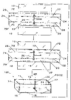
Un sac déployable pour contenant englobe un voile de confinement et un dispositif de déploiement. Dans une version, le dispositif de déploiement englobe un dispositif à vessie gonflable pourvu de multiples longerons fixés ou intégrés au voile et qui facilitent le déploiement et le soutien du sac dans le contenant. De l'air peut servir de milieu de gonflage. Le sac peut être déployé dans le contenant et être utilisé comme doublure. Le contenant peut être un caisson à vide.


Abrégé anglais

A deployable bag for a container embraces a containment web and a deployment system. In one embodiment, the deployment system embraces an inflatable bladder system that provides a plurality of ribs attached to or integrally part of the web that assist in deploying and supporting the bag in the container. Air may be employed as an inflation medium. The bag can be deployed in the container and employed as a liner. The container can be a vacuum box.

Revendications

Note : Les revendications sont présentées dans la langue officielle dans laquelle elles ont été soumises.


We claim:
1. In combination, a deployable bag and an industrial vacuum
box container, wherein:
the deployable bag includes a containment web and a
deployment system, wherein the containment web has
a bottom and sides, and a size that is at least as
extensive as an inner bottom and a lower portion of
inner sides of the container in which it is to be
employed; and the deployment system embraces an
inflatable bladder system that provides a plurality of
ribs attached to or integrally part of the web that
assist in deploying and supporting the bag, which can be
deployed inside the container from a position outside
the container when the bag is placed inside the container
for deployment therein; and
the industrial vacuum box container, inside which said
bag resides and which includes the inner bottom and
inner sides, further includes an interior defined by the
inner bottom, the inner sides, and a top, with an intake
port through which industrial waste can be conveyed
into the bag in the box through use of a vacuum through
a drawthrough port, and a top access port for access to
the interior of the container.

2. The combination of claim 1, wherein the inflatable
bladder system is pneumatic; the web bottom is at least about
three feet (about 91 cm) wide; and the web sides are at least
about two feet (about 61 cm) high.
3. The combination of claim 2, in which said bag is fully
deployed as a liner.
4. The combination of claim 2, wherein the ribs are
tubelike; the web bottom is substantially rectangular with a
length at least about ten feet (about 3.15 m); and the inflatable
bladder system includes a delivery tube system that has access to
the inflatable bladder system substantially central of the web
bottom.
5. The combination of claim 4, wherein the ribs form an
X-type pattern with respect to the web.
6. The combination of claim 4, wherein the ribs include a
plurality of lengthwise ribs that extend lengthwise along the
bottom and up short sides of the web.
7. The combination of claim 6, wherein the ribs include a
plurality of widthwise ribs that extend widthwise along the
bottom and up long sides of the web.
11

8. The combination of claim 7, wherein the ribs include a
top rib along at least a part of a top of at least one of the
sides of the web.
9. The combination of claim 7, wherein the top rib extends
along the short and long sides of the web.
10. The combination of claim 8, wherein the top rib extends
along the short and long sides of the web.
11. The combination of claim 10, wherein the web consists
essentially of the bottom and sides, with no top portion thereto;
and there are about from two to five lengthwise ribs, and about
from two to ten widthwise ribs.
12

Description

Note : Les descriptions sont présentées dans la langue officielle dans laquelle elles ont été soumises.


CA 02439708 2003-09-04
DEP YABLE SAG FORA VACUUM BO
FIELD AND PURVIEW
The present invention concerns a bag useful as a liner for a
container. In a preferred embodiment, the bag has a set of
inflatable ribs for deployment in and use during operation of the
container. The invention also concerns making and using the bag
as well as a combination of the bag and the container. The
container, beneficially, can be an industrial vacuum box.
BACKGROUND TO THE INVENTION
Large vacuum boxes are employed in the industrial setting for
containing suctioned wastes which often are removed and contained
as a type of slurry. It frequently occurs that, when the vacuum
box is to be emptied, the solids have settled and are difficult
to remove from the box. Thus, reemployment of the vacuum box
becomes impossible, and the vacuum box will require extensive
cleaning as the waste cannot be left in the container.
In attempting to address such concerns, various vacuum box
1

CA 02439708 2010-12-01
liners have been proposed. See, e.g., U.S. patent Nas. 4,385,953
to Beck, and 5,098,364 to Schilling. However, installation of
such liners can be cumbersome and dangerous, and their use can be
problematic, as most industrial vacuum box containers require
confined space entry. Note, U.S. patent No. 5,752,731 to crone.
It would be desirable to ameliorate or solve such problems.
FURTHER DISCLOSURE OF THE INVENTION
The present invention provides a deployable bag for a
container comprising a containment web and a deployment system.
The bag can be employed in the container as a liner.
According to another aspect of the invention, there
is provided in combination, a deployable bag and an
industrial vacuum box container, wherein the deployable
bag includes a containment web and a deployment system,
wherein the containment web has a bottom and sides, and a
size that is at least as extensive as an inner bottom and
a lower portion of inner sides of the container in which
it is to be employed; and the deployment system embraces
an inflatable bladder system that provides a plurality of
ribs attached to or integrally part of the web that assist
in deploying and supporting the bag, which can be deployed
inside the container from a position outside the container
when the bag is placed inside the container for deployment
2

CA 02439708 2010-12-01
therein; and the industrial vacuum box container, inside
which said bag resides and which includes the inner bottom
and inner sides, further includes an interior defined by
the inner bottom, the inner sides, and a top, with an
intake port through which industrial waste can be conveyed
into the bag in the box through use of a vacuum through a
drawthrough port, and a top access port for access to the
interior of the container.
The invention is useful in waste containment.
Significantly, by the invention, one or more problems in the
art are ameliorated if not solved. Accordingly, disposal of
industrial and/or environmental waste from containers in general
and large vacuum boxes in particular is made more efficient in
kind, and ready reemployment of the vacuum boxes is made possible
and streamlined. By employment of the bag of the invention,
nearly all of the waste entering a vacuum box can be removed
readily, to notably include solids, by disposing of the bag,
which serves as a liner to the box, and the contents of the bag
together. Moreover, the bag of the invention is self-deployable,
affording ease of installation in addition to reliability in use.
Thus, most beneficially, the rigors and dangers of confined space
entry can be avoided. Then too, the container can retain its
2a

CA 02439708 2003-09-04
full capacity, and it may be less likely to prematurely corrode,
since dramatically less waste is left behind after emptying of
the container. The invention is efficient to make and use.
Numerous further advantages attend the invention.
The drawings form part of the specification hereof. With
respect to the drawings, which are not necessarily drawn to
scale, the following is briefly noted:
FIG. 1 in a schematic plan view of the making and test
deployment of an embodiment of a deployable bag for a container
of the invention, where the containment web of the bag is made
from more than one piece, and the deployment system is made
separate from and then attached to the web.
FIG. 2 is a schematic plan view of the making and test
deployment of another embodiment of a deployable bag for a
container of the invention, where the containment web of the bag
is made from one piece, and the deployment system is made
separate from and then attached to so that its ribs extend above
the web.
FIG. 3 is a sectional plan view of another embodiment of a
deployable bag for a container of the invention, otherwise taken
along 3/4-3/4 of FIG_ 2, where the containment web and deployment
system ribs of the bag are made from the same piece of material.
FIG. 4 is a sectional plan view of another embodiment of a
deployable bag for a container of the invention, otherwise taken
along 3/4-3/4 of FIG. 2, where the containment web and deployment
3

CA 02439708 2003-09-04
system ribs of the bag are made from the same pieces of material,
embracing two sheets joined together.
FIG. 5 is a perspective plan view of another embodiment of a
deployable bag for a container of the invention, with deployment
system ribs positioned more extensively in the containment web.
FIG. 6 is a side, sectional view of an embodiment of a
deployable bag for a container of the invention, in place in an
industrial vacuum box and ready for full deployment.
FIG. 7 is a side, sectional view of the embodiment of FIG. 6,
fully deployed and in use in the industrial vacuum box of FIG. 6.
FIG. 8 is a top plan view of another embodiment of a
deployable bag for a container of the invention, which is made
for a particular style of vacuum box.
FIG. 9 is a perspective plan view of the bag of FIG. 8,
deployed inside the vacuum box for which it is made.
FIG. 10 is a cross sectional plan view of the deployed bag in
the vacuum box of FIG. 9, taken along a lengthwise direction.
FIG. 11 is a cross sectional plan view of the deployed bag in
the vacuum box of FIG. 9, taken along a widthwise direction.
FIG. 12 is a top plan view of another embodiment of a
deployable bag for a container of the invention, which has
deployment system ribs in an X-type configuration.
FIG. 13 is a top plan view of another embodiment of a
deployable bag for a container of the invention, which has
deployment system ribs in another X-type configuration.
4

CA 02439708 2003-09-04
The invention can be more fully understood by the following
detail, which may be read in view of the drawings. Such is to be
taken in an illustrative and not necessarily limiting sense.
in general, the deployable bag for a container includes a
containment web and a deployment system. The containment web is
made to contain appropriate waste products in the finished bag,
and the deployment system is made to deploy or position, or to
assist in deploying or positioning, the finished bag in a
container generally corresponding in size and shape to the bag.
Advantageously, the container is a vacuum box_ However, other
containers may benefit from employment of the deployable bag of
the invention. In particular, industrial containers can benefit,
for example, intermodal containers, say, for rail or over the
road or on the sea. A particular benefit is that the deployable
bag of the invention can be used in containers having confined
space difficulties or in which ingress or egress of personnel in
setting up other liners in the containers is a problem.
Any suitable material(s) or contrivance(s) may be employed to
provide the containment web and deployment system. For instance,
the web may be made of a textile or mesh material, say, of cloth,
natural and/or synthetic, or even metal, which may be impregnated
or coated with a substance resistant to water or other solvent
that the finished bag may be expected to contact; a natural or
synthetic rubber; and/or a plastic sheet, for example, a
polyolefin, say, polyethylene and/or polypropylene, poly vinyl

CA 02439708 2003-09-04
chloride, polytetrafluoroethylene, polystyrene, polyurethane,
polysulfide, nylon, polyterephthalate, polysilicone, and so forth
and the like, which may or may not be provided with reinforcing
fibers. The deployment system, for instance, may be provided by
a mechanical system such as the release of springs, extension of
booms, say, telescoping and/or folding scissor-like booms; by a
closed pneumatic system such as provided through employment of a
chemical reaction which releases a gas in a bladder; and/or by an
inflatable system such as pumping of a gas, say, air or steam, or
a liquid, say, water or hydraulic fluid, in a bladder, and so
forth and the like -- with the bladders made of any suitable
material(s) such as imperforate sheets of an impregnated textile
or mesh; a natural or synthetic rubber; and/or a plastic sheet,
for example, polyolefin, say, polyethylene and/or polypropylene,
poly vinyl chloride, polytetrafluoroethylene, nylon, polystyrene,
polyurethane, polysulfide, polyterephthalate, polysilicone, and
so forth and the like, which may or may not be reinforced with
fibers. The bag can be employed in the container as a liner. An
elongate member such as a stick, prod or the like may be used
with benefit in positioning the liner before its deployment.
With reference to the drawings, deployable bag 100 for a
container includes containment web 10 and deployment system 20.
The bag 100 serves as a liner in vacuum box 30 into which
industrial waste 40 is conveyed through use of a vacuum.
The containment web 10, which may be made of any suitable
6

CA 02439708 2003-09-04
material and have any suitable thickness and lateral or vertical
component containing dimensions, for instance, a suitable plastic
sheet about from two to twenty-five mils thick, for example, a
polyethylene sheet about five or six mils thick, which may be
reinforced, say, with nylon strands, has sides 11, 12, 13, 14,
for example, some two to five feet high, say, about three feet
high, and bottom 15, for example, some three to twelve feet in
width, say, about seven and one half feet in width, and some tan
to fifty feet in length, say, about twenty-three or twenty-six
feet in length. When making the web 10 from flat stock,
fastenings 18, for example, nylon stitches, can be employed. The
fastenings 18 may also be provided by stapling, snapping, hook
and loop system such as Velcro (Reg. U.S. Pat. & Tm. Off)
material, gluing and/or hot melt welding. As an alternative, the
web 10 may be formed into a baglike shape from one piece of
material through vacuum molding, or blow or injection molding may
be employed to form a one-piece, seamless bag-like web component.
Intake or drawthrough port avoidance bay 19 may be provided in a
wall such as the wall 12, by any suitable method such as by
cutting out material from the wall 12 to form the bay 19.
The deployment system 20, for instance, of the inflatable
type, which may be made of any suitable material and have any
suitable thickness and area dimensions, for instance, a suitable
plastic sheet about from two to twenty-five mils thick, for
example, an unreinforced polyethylene sheet about five or six
7

CA 02439708 2003-09-04
mils thick, may have bladder 22, fastening tab 24 and inflation
delivery tube system 26, which may be provided by any suitable
device such as flexible tube, rigid or semi-rigid pipe. As an
expedient, the system 26 may include standard tire valve stem
without the valve, which is attached through the center of a
six-inch square piece of one eighth of an inch thick rubber that
is fastened to the polyethylene sheet at its bottom end and to
which the end of a one quarter inch plastic tube is installed.
of course, the tube or pipe may be otherwise connected to the
bladder 22 such as by a direct connection thereto without an
intervening standard valve stem, and be heat welded or glued to
the sheet at a hole therein. A short stem may simply be molded
with, or by heat welding or gluing attached to, the sheet, to
which a tube or pipe is later attached to provide the system 2e.
Although any suitable fluid can serve as an inflation medium, air
is preferred. The bladder 22 is typically formed into one or
more tubelike ribs, for instance, about from two to five
lengthwise ribs which extend lengthwise along the bottom 15 of
the web 10 and up the short sides 11, 13; optionally, there may
be provided one or more bladder ribs 22, for instance, about from
two to ten widthwise ribs which extend widthwise along the bottom
15 of the web 10 and up the long sides 12, 14; and, as a further
option, a bladder rib 22 may extend along a part or the whole of
the top of the side(s) 11, 12, 13, 14, say, about the top of
opposing short sides 11 and 13 or long sides 12 and 14, or about
8

CA 02439708 2003-09-04
the top of all the sides 11, 12, 13 and 14. The ribs 22 help
support the bag 100. To hold the containment web 10 to the
deployment system 20, fastenings 28, for instance, stitching, for
example, of nylon, can be employed. The fastenings 28 may also
be provided by stapling, snapping, hook and loop system such as
Velcro (Reg. U.S. Fat, & Tm. off) material and/or gluing. Hot
melt welding 29 may be employed as well, especially to help form
the bladder 22 and tab 24, or when the web 10 and bladder 22 are
formed from the same piece of material. Again, the web 10 and
bladder 22 may be integrally formed from one piece of material.
In use, the bag 100 serves as a liner in the vacuum box 30,
which has top access port 31, intake port 32, and drawthrough
port 33. The industrial waste 40 is conveyed into the liner 100
in the box 30 through use of a vacuum. When it in time to empty
the waste 40, waste 40 and liner 100 together are disposed of
through standard emptying door 34, which may open horizontally by
swinging on side hinges 34S or vertically by swinging on top
hinges 34T.
The present invention is thus provided. Various features,
parts, subcombinations and combinations can be employed with or
without reference to other features, parts, subcombinations or
combinations in the practice of the invention, and numerous
adaptations and modifications can be effected within its spirit,
the literal claim scope of which is particularly pointed out as
follows;
9

Dessin représentatif
Une figure unique qui représente un dessin illustrant l'invention.
États administratifs

2024-08-01 : Dans le cadre de la transition vers les Brevets de nouvelle génération (BNG), la base de données sur les brevets canadiens (BDBC) contient désormais un Historique d'événement plus détaillé, qui reproduit le Journal des événements de notre nouvelle solution interne.

Veuillez noter que les événements débutant par « Inactive : » se réfèrent à des événements qui ne sont plus utilisés dans notre nouvelle solution interne.

Pour une meilleure compréhension de l'état de la demande ou brevet qui figure sur cette page, la rubrique Mise en garde , et les descriptions de Brevet , Historique d'événement , Taxes périodiques et Historique des paiements devraient être consultées.

Historique d'événement

Description Date
Inactive : Périmé (brevet - nouvelle loi) 2023-09-05
Représentant commun nommé 2019-10-30
Requête pour le changement d'adresse ou de mode de correspondance reçue 2018-06-08
Requête pour le changement d'adresse ou de mode de correspondance reçue 2018-05-14
Requête visant le maintien en état reçue 2016-08-26
Inactive : Paiement - Taxe insuffisante 2016-07-25
Requête visant le maintien en état reçue 2016-07-14
Lettre envoyée 2014-03-21
Inactive : Correspondance - Transfert 2014-03-11
Inactive : Lettre officielle 2014-01-31
Inactive : Transfert individuel 2013-12-17
Requête visant le maintien en état reçue 2013-09-04
Accordé par délivrance 2011-12-13
Inactive : Page couverture publiée 2011-12-12
Inactive : Lettre officielle 2011-09-22
Exigences relatives à la révocation de la nomination d'un agent - jugée conforme 2011-09-22
Exigences relatives à la nomination d'un agent - jugée conforme 2011-09-22
Demande visant la révocation de la nomination d'un agent 2011-09-09
Demande visant la nomination d'un agent 2011-09-09
Inactive : Lettre officielle 2011-09-01
Exigences relatives à la révocation de la nomination d'un agent - jugée conforme 2011-09-01
Inactive : Lettre officielle 2011-09-01
Exigences relatives à la nomination d'un agent - jugée conforme 2011-09-01
Demande visant la révocation de la nomination d'un agent 2011-08-26
Demande visant la nomination d'un agent 2011-08-26
Demande visant la révocation de la nomination d'un agent 2011-08-19
Inactive : Correspondance - Poursuite 2011-08-19
Demande visant la nomination d'un agent 2011-08-19
Lettre envoyée 2011-08-15
Inactive : Transfert individuel 2011-08-05
Inactive : Lettre officielle 2011-08-02
Inactive : Demande ad hoc documentée 2011-08-02
Inactive : Lettre officielle 2011-08-02
Inactive : Taxe finale reçue 2011-07-18
Préoctroi 2011-07-18
Demande visant la révocation de la nomination d'un agent 2011-07-18
Demande visant la nomination d'un agent 2011-07-18
Un avis d'acceptation est envoyé 2011-01-18
Lettre envoyée 2011-01-18
Un avis d'acceptation est envoyé 2011-01-18
Inactive : Approuvée aux fins d'acceptation (AFA) 2010-12-14
Modification reçue - modification volontaire 2010-12-01
Inactive : Dem. de l'examinateur par.30(2) Règles 2010-06-01
Exigences relatives à la révocation de la nomination d'un agent - jugée conforme 2009-08-11
Inactive : Lettre officielle 2009-08-11
Exigences relatives à la nomination d'un agent - jugée conforme 2009-08-11
Demande visant la nomination d'un agent 2009-07-31
Demande visant la révocation de la nomination d'un agent 2009-07-31
Lettre envoyée 2008-09-11
Requête d'examen reçue 2008-06-19
Exigences pour une requête d'examen - jugée conforme 2008-06-19
Déclaration du statut de petite entité jugée conforme 2008-06-19
Requête visant une déclaration du statut de petite entité reçue 2008-06-19
Toutes les exigences pour l'examen - jugée conforme 2008-06-19
Inactive : Demande ad hoc documentée 2005-05-20
Demande publiée (accessible au public) 2004-03-05
Inactive : Page couverture publiée 2004-03-04
Inactive : CIB en 1re position 2003-10-22
Inactive : CIB attribuée 2003-10-22
Demande reçue - nationale ordinaire 2003-09-30
Inactive : Certificat de dépôt - Sans RE (Anglais) 2003-09-30
Déclaration du statut de petite entité jugée conforme 2003-09-04

Historique d'abandonnement

Il n'y a pas d'historique d'abandonnement

Taxes périodiques

Le dernier paiement a été reçu le 2011-07-18

Avis : Si le paiement en totalité n'a pas été reçu au plus tard à la date indiquée, une taxe supplémentaire peut être imposée, soit une des taxes suivantes :

  • taxe de rétablissement ;
  • taxe pour paiement en souffrance ; ou
  • taxe additionnelle pour le renversement d'une péremption réputée.

Les taxes sur les brevets sont ajustées au 1er janvier de chaque année. Les montants ci-dessus sont les montants actuels s'ils sont reçus au plus tard le 31 décembre de l'année en cours.
Veuillez vous référer à la page web des taxes sur les brevets de l'OPIC pour voir tous les montants actuels des taxes.

Historique des taxes

Type de taxes Anniversaire Échéance Date payée
Taxe pour le dépôt - petite 2003-09-04
TM (demande, 2e anniv.) - petite 02 2005-09-05 2005-06-27
TM (demande, 3e anniv.) - petite 03 2006-09-04 2006-04-25
TM (demande, 4e anniv.) - petite 04 2007-09-04 2007-05-01
Requête d'examen - petite 2008-06-19
TM (demande, 5e anniv.) - petite 05 2008-09-04 2008-06-19
TM (demande, 6e anniv.) - petite 06 2009-09-04 2009-08-13
TM (demande, 7e anniv.) - petite 07 2010-09-06 2010-08-18
Taxe finale - petite 2011-07-18
TM (demande, 8e anniv.) - petite 08 2011-09-06 2011-07-18
Enregistrement d'un document 2011-08-05
TM (brevet, 9e anniv.) - petite 2012-09-04 2012-09-04
TM (brevet, 10e anniv.) - petite 2013-09-04 2013-09-04
Enregistrement d'un document 2013-12-17
TM (brevet, 11e anniv.) - petite 2014-09-04 2014-09-03
TM (brevet, 12e anniv.) - petite 2015-09-04 2015-06-25
TM (brevet, 13e anniv.) - petite 2016-09-06 2016-07-14
TM (brevet, 15e anniv.) - petite 2018-09-04 2016-07-14
TM (brevet, 14e anniv.) - petite 2017-09-05 2016-07-14
TM (brevet, 18e anniv.) - petite 2021-09-07 2019-08-07
TM (brevet, 17e anniv.) - petite 2020-09-04 2019-08-07
TM (brevet, 19e anniv.) - petite 2022-09-06 2019-08-07
TM (brevet, 16e anniv.) - petite 2019-09-04 2019-08-07
Titulaires au dossier

Les titulaires actuels et antérieures au dossier sont affichés en ordre alphabétique.

Titulaires actuels au dossier
HQN INDUSTRIAL FABRICS, INC.
DAVID G. LOBBESTAEL
GLOBAL PRODUCTS SOLUTIONS OF LOUISIANA, LLC
Titulaires antérieures au dossier
MICHAEL L. NOTTLEY
PAUL N. HARDY
Les propriétaires antérieurs qui ne figurent pas dans la liste des « Propriétaires au dossier » apparaîtront dans d'autres documents au dossier.
Documents

Pour visionner les fichiers sélectionnés, entrer le code reCAPTCHA :


Pour visualiser une image, cliquer sur un lien dans la colonne description du document. Pour télécharger l'image (les images), cliquer l'une ou plusieurs cases à cocher dans la première colonne et ensuite cliquer sur le bouton "Télécharger sélection en format PDF (archive Zip)" ou le bouton "Télécharger sélection (en un fichier PDF fusionné)".

Liste des documents de brevet publiés et non publiés sur la BDBC .

Si vous avez des difficultés à accéder au contenu, veuillez communiquer avec le Centre de services à la clientèle au 1-866-997-1936, ou envoyer un courriel au Centre de service à la clientèle de l'OPIC.


Description du
Document 
Date
(aaaa-mm-jj) 
Nombre de pages   Taille de l'image (Ko) 
Description 2003-09-03 9 306
Abrégé 2003-09-03 1 13
Dessins 2003-09-03 6 147
Revendications 2003-09-03 3 67
Dessin représentatif 2003-10-21 1 13
Dessins 2010-11-30 6 146
Description 2010-11-30 10 344
Revendications 2010-11-30 3 81
Dessin représentatif 2011-11-06 1 15
Certificat de dépôt (anglais) 2003-09-29 1 159
Rappel de taxe de maintien due 2005-05-04 1 110
Rappel - requête d'examen 2008-05-05 1 127
Accusé de réception de la requête d'examen 2008-09-10 1 176
Avis du commissaire - Demande jugée acceptable 2011-01-17 1 162
Courtoisie - Certificat d'enregistrement (document(s) connexe(s)) 2011-08-14 1 102
Courtoisie - Certificat d'enregistrement (document(s) connexe(s)) 2014-03-20 1 102
Avis de paiement insuffisant pour taxe (anglais) 2016-07-24 1 90
Taxes 2005-06-26 1 30
Taxes 2006-04-24 1 31
Taxes 2007-04-30 1 40
Taxes 2008-06-18 1 36
Correspondance 2008-06-18 1 25
Correspondance 2009-07-30 2 65
Correspondance 2009-08-10 1 15
Correspondance 2009-08-10 1 17
Taxes 2009-08-12 1 200
Correspondance 2011-07-17 2 58
Taxes 2011-07-17 2 58
Correspondance 2011-08-01 1 19
Correspondance 2011-08-18 7 245
Taxes 2011-08-18 5 174
Correspondance 2011-08-25 3 117
Correspondance 2011-08-31 1 15
Correspondance 2011-08-31 1 17
Correspondance 2011-08-31 1 19
Correspondance 2011-09-08 3 101
Correspondance 2011-09-21 1 19
Correspondance 2011-08-18 7 249
Taxes 2012-09-03 3 106
Taxes 2013-09-03 3 101
Correspondance 2014-01-30 1 19
Paiement de taxe périodique 2016-07-13 2 71
Paiement de taxe périodique 2016-08-25 2 58