Note : Les descriptions sont présentées dans la langue officielle dans laquelle elles ont été soumises.
CA 02441325 2003-09-19
WO 02/076695 PCT/CA02/00384
METHOD AND APPARATUS FOR TRIMMING SHEET METAL
Technical Field
This invention relates to a method and apparatus for trimming sheet
material, typically handled in the form of large coils. More particularly, it
relates
to the method and apparatus for trimming light gauge aluminum in which the
trim
or strap is directed positively and effectively into a scrap reclamation
system.
Background Art
Light gauge aluminum coils typically undergo a process of "trimming" or
"center cutting". As the web is uncoiled, it passes over a knife roll. The
roll is
used in conjunction with stationary knives to cut thin strips of aluminum from
the
main sheet. Thus, this operation creates continuous strips of aluminum scrap
or
trim as the coil is processed. These trim strips are generally between about
1/8
and 2 inches (3 and 51 mm) wide and can be generated at speeds of up to a few
thousand feet/minute. This trim is picked up at the machine by use of "trim
tubes'. As the trim is cut from the web, a vacuum generated by large fans that
are
part of the overall "trim system" draws it into the trim tube. The trim is
carried by
the trim system to a central scrap staging area where it awaits further
processing.
As the processing speed is increased, or if the trim is especially wide, there
is a tendency for the trim to be drawn to the surface of the knife roll.
Frequently,
at some point during processing of a coil, the trim makes contact with and
adheres
to the knife roll. When this happens, the trim no longer travels into the trim
tube
but instead, wraps around the roll, quickly causing a web break, shutdown and
sometimes further problems .
Various mechanical devices, such as plate type guides constructed of thin
material such as plastic or sheet metal, have been used to try and deflect the
trim
strip from the roll and guide it into the trim tube. These have largely been
unsuccessful due to the difficulty in getting them positioned properly and
because
the trim strip tends to drag and catch on the surface of the plate. One or
more
attempts have also been made to guide the trim or scrap into the trim tube
with a
CA 02441325 2003-09-19
WO 02/076695 PCT/CA02/00384
2
jet of air blowing toward the mouth of the trim tube, i.e., in the direction
of
movement of the scrap strip. This method may be effective for thicker and
stiffer
strip, which has a tendency to escape the vacuum of the trim system and be
ejected outward towards the rewind side of the trim tube. But it is of
absolutely
no use in preventing light gauge trim (less than 0.025 mm) from being drawn to
the surface of the knife roll.
U.S. patent 4,484,500 to Reba et al. discloses apparatus to form a spirally
wound paper roll product formed from convolutions cut from a parent web. The
system includes first and second slitters and trim removal means, positioned
close
to the second slitter, with Coanda nozzles that induce a fluid flow into a
scrap
collection unit. The patent indicates that this flow is a combination of the
air flow
from the nozzles themselves and ambient air entrained therein. The air from
the
nozzle and entrained ambient air apply a ullin force to both the trim strip
and
the parent web. The combined flow draws the trim into a trim or scrap
collector
(column 5, lines 9-18, lines 33-36). In a conventional fan based trim system,
this
entire function is replaced by fans themselves.
In the system proposed by Reba et al, the Coanda nozzles must be
positioned very close to the moving web and trim strip. As is evident from the
drawings, the web used in conjunction with the Reba nozzle must be positioned
between the knife roll and the nozzle. This is opposite of several
conventional
applications. These two requirements make the nozzle very difficult, if not
impossible, to use with the configuration of many existing machines. There is
nothing in the patent which suggests that a comparable system, or any other
system employing one or more air jets, would be suitable for trimming sheet
aluminum or other metals. The rollers (150 and 152) which are critical to the
Reba
system are highly undesirable for aluminum trimming. The rollers change the
path of the strip and would most likely cause several other problems including
marking of the strip, strip wrinkles and strip breaks due to the localized
force on
the strip at the rollers.
CA 02441325 2006-O1-19
3
Disclosure of the Invention
According to one aspect of the invention, there is provided an apparatus for
trimming scrap from a moving metal foil, comprising: a knife roll adapted to
support said foil as it moves around said roll; a blade biased against said
foil as the
web moves around the roll; said blade being adapted to trim a strip of scrap
from
said foil; and a nozzle; characterized in that the nozzle is positioned on the
same
side of the strip as the knife roll, and is mounted to direct an air stream
against the
surface of the knife roll in the area where the trim strip leaves the roll and
in a
direction opposite to the travel of the knife roll and trim strip thereby
causing the
air stream to press against the side of the trim strip adjacent to the knife
roll and
force the trim strip away from the knife roll.
According to another aspect of the invention, there is provided a method of
slitting metal foil comprising: passing a supply web of the foil between a
knife roll
and a blade pressed against the foil, whereby the foil is slit into one or
more
product foils and at least one trim strip; and directing a stream of air
against the
trim strip from a nozzle; characterized in that the nozzle is positioned on
the same
side of the strip as the knife roll, and is mounted to direct said stream of
air against
the surface of the knife roll in the area where the trim strip leaves the roll
and in a
direction opposite to the travel of the knife roll and trim strip thereby
causing the
air stream to press against the side ofthe trim strip adjacent to the knife
roll and
force the trim strip away from the knife roll.
This invention provides a simple and effective method and apparatus for
controlling the movement of a strip of metallic trim into a scrap reclamation
system. It utilizes an air nozzle that does not resemble Reba's, either
structurally
or in method of operation. The orifice of Reba's nozzle is a thin slit --
(Coanda
nozzles typically have slits on the order of 0.002" (0.05 mm) wide). It
produces a
high velocity stream of turbulent air which tends to conform to a surface
downstream of the nozzle, as long as that surface has no sharp corners or
other
such discontinuities. In the Reba nozzle the Coanda effect causes the air to
flow
around the curved edge of the nozzle into the scrap tube. As mentioned above,
the
air from the Coanda nozzle induces ambient air to flow in the same direction,
i.e.,
CA 02441325 2006-O1-19
3a
into the scrap tube. This tends to create a slightly reduced air pressure
between the
knife roll and the trim strip, in the area where the trim strip leaves the
roll.
The air nozzles of this invention operate in a different manner. Instead of
causing a thin high velocity jet of turbulent air to wrap around the end of
the
nozzle, one or more nozzles direct a stream of air between the knife roll and
the
trim strip in the area where the trim strip leaves the knife roll. Some
embodiments
of this invention do take advantage of the same "wall attachment" effect
relied on
by Reba et al to guide the air around the knife roll to the area where the
trim strip
separates from the roll. However, instead of causing an air stream to wrap
around
the end of the nozzle and flow in the scrap tube, as in Reba's system, the
nozzle of
this invention directs an air stream against the surface of the knife roll and
in a
direction opposite to the travel of the knife roll and trim strip. The stream
of air
follows the contour of the roll and provides a wedge between the strip and the
roll.
This positively forces the trim strip away from the knife roll, rather than
relying
on whatever tension may be induced in the strip in systems such as Reba's. The
nozzles of this invention can be a relatively large distance from the web. The
position of the nozzle is not overly critical. Nozzle placement is on the same
side
of the strip as the knife roll.
As noted above, Reba's Coanda nozzles must be positioned very close to
the moving web and trim strip, between the knife roll and the nozzle. This is
CA 02441325 2003-09-19
WO 02/076695 PCT/CA02/00384
4
opposite to several conventional applications, and make this nozzle very
difficult,
if not impossible, to use with many existing machines. The systems of this
invention avoid this problem. Moreover, they do not require the rollers which
are
critical to the Reba system. These would be highly undesirable for aluminum
trimming because they would change the path of the strip and would most likely
cause several other problems, including marking of the strip, strip wrinkles
and
strip breaks.
Other features and advantages of this system will be apparent from the
following detailed description.
Brief Description of the Drawing-s
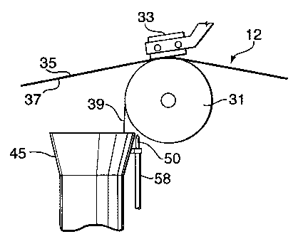
Figure 1 in a schematic side elevation view illustrating the movement of
sheet metal through a slitter embodying this invention.
Figure 2 is an enlarged evaluation view, from the same viewpoint on
Figure 1, illustrating the movement of the fixed web into a slitting station,
and the
movement of product webs and trim strips from the station.
Figure 3 is an end elevation view of a product web and a trim strip leaving
the trimming station.
Figure 4 is a detailed elevation view taken along lines 4-4 in Figure 2, of
the trim tube and air knife nozzle.
Figure 5 is a top plan view of the trim tube and air knife nozzle.
Figure 6 is an enlarged side view of the tip of the nozzle shown in Figures
2, 4 and 5.
Figure 7 is an end view of the tip shown in Figure 6, showing the orifice in
the nozzle.
Best Mode for Carryin~ Out the Invention
Figure 1 is a partial side elevation view of a slitter, generally referred to
as
10, embodying this invention. A thin, doubled web 12 of aluminum, comprising
two individual or separate sheets 11,13, is fed to slitter 10 from a supply
coil 16
on a stand 18. The doubled web 12 is typically about 0.0005 inches (0.013 mm)
CA 02441325 2003-09-19
WO 02/076695 PCT/CA02/00384
to about 0.002 (0.5 mm) inches thick and about 24 to 52 inches (61 to 132 cm)
wide. The individual sheets 11, 13 that make up the doubled web are typically
between about 0.0063 mm and about 0.025 mm inches thick. The incoming web
passes around idler rollers 23, 25, 27 to a slitting station. In the slitting
station the
web passes over and around knife roll 31. Two or more slitters 33 (fixed razor
blades are illustrated, but rotary blades could also be used) are biased
against the
web as it passes around the knife roll and make the desired cuts in the web.
The knife roll 31, as is typical of rolls used in the slitting of light metal
sheets or webs, has a series of alternating square grooves and lands, each
approximately 1/32" (0.79 mm) wide. The lands support the web, and each
slitter
blade projects part way into one of the grooves, which helps the blade cut the
web
cleanly.
Figures 2 and 3 illustrate one of a pair of slitters in the illustrated
system:
the slitter on the near end (Figure 2) or right hand end (Figure 3) of knife
roll 31.
1 S A complimentary slitter (not shown) is positioned at the other and of roll
31.
Each removes a trim strip from one edge of the web. The trim strips are
typically
about 1 /8 inch (3 mm) to about 2 '/z inches (63 mm) wide; depending on the
desired final width and cracks or other defects at the edge of the web. If
narrower
product sheets are desired, an additional pair of slitters may be positioned
in the
center of knife roll 31. The center slitters are typically positioned about
1/8 inch
(3 mm) to about 1 inch (25 mm) apart, generating a trim strip of the same
width.
In the illustrated slitter the feed web 12 is slit in into two product webs
35,
37, which correspond respectively to the upper sheet 11 and lower sheet 13 of
doubled web 12, and two doubled trim strips. The doubled trim strip 39 from
the
near or right end of web 12 is shown in Figures 2 and 3. Product web 35 is
wound
on upper rewind coil 41, and product web 37 is wound on lower rewind coil 43,
using conventional rewind systems. Upper rewind coil 41 and lower rewind coil
43 pull the product webs 35, 37 and feed web 12 through the slitter 10,
typically at
speeds of about 1,000 to 2,500 feet (305 to 762 m) per minute.
The trim strip 39 is collected by a trim tube 45 (utilizing vacuum generated
by remote fans, not shown) and carried by the remote fans to a central scrap
staging area for further processing. The trim strip from the other end of
knife roll
CA 02441325 2003-09-19
WO 02/076695 PCT/CA02/00384
6
31 and any trim strip or strips that may be trimmed from the center of the web
are
collected by similar trim tubes (not shown) and also carried to the central
scrap
staging area. A vacuum generated within the tube by large fans (not shown)
helps
to draw the trim strip 39 into the trim tube 45. Alternatively or
additionally,
nozzles may inject air into the trim tube 45, near its mouth, and induce a
flow of
entrained air into the trim tube. The drawing or pulling force of the ambient
air
entrained by the remote fan system, by inductive nozzles, or a combination of
one
or more fans and nozzles is frequently insufficient to prevent the trim strip
from
being pulled to the surface of the knife roll. The design of the Reba nozzle
has
this same deficiency.
In the illustrated system, however, an air knife nozzle 50 mounted at the
upper edge of trim tube 45, between the trim strip 39 and knife roll, directs
a
stream of air against knife roll a short distance from the area where the trim
strip
39 leaves the knife roll 31. The nozzle emits a stream of fluid that flows
generally
outward from the nozzle, with minimal Coanda effects around the side of the
nozzle, flows around the side of the knife roll (where it is subject to wall
attachment or Coanda effects) and presses against the lower side of the strip,
i.e.
the side adjacent to the knife roll, in the area where the trim strip
separates from
the roll The stream generates a positive pressure against the trim strip 39,
which
positively forces the trim strip away from the knife roll.
The illustrated nozzle 50 may be constructed simply by flattening the end
of a copper tube to produce the illustrated narrow, elongated orifice 52. The
illustrated nozzle terminates in an end or discharge face 54 that is
substantially
perpendicular to the bore of the nozzle. The relatively sharp edge or
discontinuity
between discharge face 54 and the bore of the nozzle reduces any Coanda
effects
around the side of the nozzle.
The size and shape of the orifice, and the orientation of the nozzle may be
adjusted to suit differing materials, sheet, equipment and/or processes.
Various
other nozzles, commercial or otherwise, that will provide a positive stream of
air
against the trim strip in the area where it leaves the knife roller may also
be used.
In some instances the nozzle may be angled so that the stream of air is aimed
CA 02441325 2003-09-19
WO 02/076695 PCT/CA02/00384
7
directly into the area where the trim strip leaves the roll, but superior
performance
is generally obtained by directing the air stream against the knife roll, as
illustrated, which tends to smooth our turbulence and other discontinuities in
the
air stream.
Air is supplied to nozzle 50 through a tube 58, and the flow rate is adjusted
by a flow regulating needle valve (not shown) mounted with other controls for
the
slitter. The flow may be adjusted manually to the rate which provides the most
satisfactory operation. In typical installations, nozzle pressures of 1 S to
20 psi
(103 to 138 kPa) and flow rates of 30 to 90 SCFH have been satisfactory. These
conditions generate an air stream that provides a positive force against trim
strip
39, which helps to insure that the trim strip will not remain attached to the
knife
roll and disrupt the slitting operation.
As may be seen from the foregoing description, this invention provides a
system for positively, effectively and economically separating trim scrap from
the
surface of the knife roll of a slitter. The nozzles of this invention provide
a wedge
of air that generates a positive force on the trim strip in the area where the
strip
separates from the knife roll. This positively urges or moves the trim strip
away
from the knife roll and towards the scrap reclamation trim tubes, which
substantially eliminates or reduces the risk that the trim will adhere to the
knife
roll and cause time consuming and expensive production problems. Moreover,
unlike the Reba et al system, it does not require critical location of the
nozzles in
areas that are unsuitable for current slitters.