Note : Les descriptions sont présentées dans la langue officielle dans laquelle elles ont été soumises.
CA 02441693 2003-09-08
WO 02/085441 PCT/US02/08788
MICROCATHETER WITH IMPROVED DISTAL TIP AND TRANSITIONS
Field of the Invention
The present invention relates generally to intravascular catheters for
performing medical procedures. More particularly, the present invention
relates to
intravascular catheters with improved shaft and distal tip designs.
Background of the Invention
Intravascular catheters are used in a wide variety of relatively non-invasive
medical procedures. Such intravascular catheters may be used for diagnostic or
therapeutic purposes. Generally, an intravascular catheter allows a physician
to
remotely perform a medical procedure by inserting the catheter into the
vascular
system of the patient at a location that is easily accessible and thereafter
navigating
the catheter to the desired target site. By this method, virtually any target
site in the
patient's vascular system may be remotely accessed, including the coronary,
cerebral,
and peripheral vasculature.
Typically, the catheter enters the patient's vasculature at a convenient
location
such as a blood vessel in the neck or near the groin. Once the distal portion
of the
catheter has entered the patient's vascular system, the physician may urge the
distal
tip forward by applying longitudinal forces to the proximal portion of the
catheter.
Frequently the path taken by~ a catheter through the vascular system is
tortuous,
requiring the catheter to change direction frequently. In some cases, it may
even be
necessary for the catheter to bend ninety degrees or more. In order for the
catheter to
navigate a patient's tortuous vascular system, it is desirable that
intravascular
catheters be very flexible, particularly near the distal end.
The distance between the access site and the target site is often in excess of
100 cm. The inside diameter of the vasculature at the access site is often
less than 2
cm, and the inside diameter of the vasculature at the target site is often
less than 0.5
cm. Accordingly, intravascular catheters must be relatively long and thin.
Furthermore, in order to navigate through the. patient's tortuous vascular
system,
intravascular catheters must be very flexible. It is also desirable that
intravascular
catheters be relatively soft in order to minimize the probability of damaging
vascular
tissue.
Intravascular catheters typically have a radiopaque portion and are guided
through the patient's vascular system with the assistance of x-ray
fluoroscopy. In this
CA 02441693 2003-09-08
WO 02/085441 PCT/US02/08788
manner, a physician may manipulate the proximal end of the catheter and
fluoroscopically monitor the corresponding movement of the distal end of the
catheter. As such, it is desirable that intravascular catheters be
sufficiently radiopaque
along their length and particularly at their distal end such that the
physician is able to
clearly monitor the progress of the catheter as it is being advanced from the
vascular
access site to the vascular target site.
After the intravascular catheter has been navigated through the patient's
vascular system with the distal end thereof adjacent the target site, the
catheter may be
used for various diagnostic and/or therapeutic purposes. Frequently,
diagnostic and
therapeutic techniques require the infusion of fluids through the catheter.
For
example, it may be desirable to inject radiopaque contrast media through the
catheter
to provide enhanced fluoroscopic visualization for diagnostic purposes, or to
inject
pharmaceutical solutions (i.e., drugs) to the target site for therapeutic
purposes.
The blood vessels in the brain frequently have an inside diameter of less than
3 mm. Accordingly, it is desirable that intravascular catheters intended for
use in
these blood vessels have an outside diameter which allows the catheter to be
easily
accommodated by the blood vessel. The path of the vasculature inside the brain
is
highly tortuous, and the blood vessels are relatively fragile. Accordingly, it
is
desirable that the distal portion of a catheter be sized appropriately and be
atraumatic
for the neurological vasculature.
Summary of the Invention
The present invention comprises a unique intravascular catheter that
incorporates a number of refinements to the shaft and distal tip. According to
a
preferred embodiment of the invention, a catheter comprises a shaft having a
proximal
end, a distal end, and a lumen. A hub is typically disposed at the proximal
end and a
distal tip is disposed at the distal end. The shaft may comprise multiple
layers,
including an inner liner, a second layer, a third layer, and a fourth layer.
The second layer may be disposed over the inner liner extending from the
proximal end of the shaft to a distal terminus. The distal terminus may be
about 4
millimeters from the distal end. The absence of the second layer between the
distal
terminus and the distal end of the shaft improves the physical properties of
the
catheter. For example, the shaft may be more flexible or generally softer near
the
distal end, and may be more xeadily thermoformed.
-2-
CA 02441693 2003-09-08
WO 02/085441 PCT/US02/08788
The third layer may be disposed over the second layer and preferably
comprises a coil that is wound over the second layer. The coil may be arranged
in a
single coil region near the distal end of the shaft. The single coil region is
understood
to be a single layer of coil wound around the second layer along a
longitudinal axis
thereof. The coil may further include a multiple coil region near the proximal
end of
the shaft wherein the coil is wound multiple times around the second layer
along the
longitudinal axis thereof.
The fourth layer may be disposed over the third layer and may include a taper.
Preferably, the taper decreases the diameter of the shaft near the distal end
thereof.
The decrease in diameter may comprise a suitable reduction in size appropriate
for
multiple uses of the catheter. For example, a generally small diameter distal
tip may
be used for procedures involving treatment of relatively small blood vessels.
Brief Description of the Drawings
Figure 1 is a plan view of an intravascular catheter with an improved shaft,
distal tip, and transitions according to a preferred embodiment of the
invention;
Figure 2 is an enlarged view of a shaft of the intravascular catheter shown in
Figure 1;
Figure 3 is an enlarged view of an alternative shaft of the intravascular
catheter shown in Figure l; and
Figure 4 is an enlarged view of another alternative shaft of the intravascular
catheter shown in Figure 1.
Detailed Description of the Preferred Embodiments
The following description should be read with reference to the drawings
wherein like reference numerals indicate like elements throughout the several
views.
The detailed description and drawings depict select embodiments and are not
intended
to be limiting.
Figure 1 is a plan view of an intravascular catheter 10 with an improved
shaft,
distal tip, and improved transitions according to a preferred embodiment of
the
invention. The intravascular catheter 1 Q comprises a shaft 12 having a
proximal end
14 and a distal end 16. A hub 18 is typically disposed at proximal end 14 of
shaft 12
and a distal tip 20 having a shapable length is disposed at distal end 16 of
shaft 12.
Shaft 12 further comprises a lumen 22 as best seen in Figure 2. Lumen 22 may
be a
guidewire lumen and/or an infusion lumen. Lumen 22 may have a diameter
-3-
CA 02441693 2003-09-08
WO 02/085441 PCT/US02/08788
compatible with a guide wire having an outside diameter of about 0.010 to
0.014
inches.
Shaft 12 comprises multiple layers including an inner liner 24. Preferably,
inner liner 24 comprises polytetrafluoroethylene (PTFE).
Polytetrafluoroethylene is
a preferred material because it creates a smooth, low-friction surface for the
passage
of other devices or fluids through catheter 10. In an alternate embodiment,
inner liner
24 may comprise materials including, but not limited to, thermoplastics, high
performance engineering resins, fluorinated ethylene propylene (FEP), polymer,
polyethylene (PE), polypropylene (PP), polyvinylchloride (PVC), polyurethane,
polyether-ether ketone (PEED), polyimide, polyamide, polyphenylene sulftde
(PPS),
polyphenylene oxide (PPO), polysufone, nylon, or perfluoro(propyl vinyl ether)
(PFA).
Inner liner 24 may be formed by extrusion over a mandrel. Extrusion may
result in inner liner 24 having a thickness of about 0.0005 inches to .00125
inches and
a diameter of about 0.0175 inches to 0.019 inches over a length of about 135
cm to
200 cm. In an alternate embodiment, inner liner 24 may be formed by Lamination
over a mandrel. The mandrel may, for example, comprise nitinol and have a
diameter
of about 0.0165 inches. A person of ordinary skill in the art would be
familiar with
processes and equipment suitable for forming inner liner 24 according to
multiple
embodiments of the present invention.
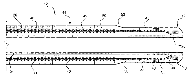
A second layer 26 is disposed over inner liner 24. Second layer 26 is
comprised of polyether block amide (PEBA). Polyether block amide is
commercially
available from Atochem Polymers of Birdsboro, Pennsylvania, under the trade
name
PEBAX. Second layer 26 may comprise PEBAX 55 having a diameter of about
0.0185 inches to 0.022 inches and a length of about 132 cm to 200 cm.
Second Layer 26 extends from proximal end 14 of shaft 12 to a distal terminus
28. Distal terminus 28 is set back from distal end 16 a distance that is equal
to or
greater than the shapable length of distal tip 20. For example, distal
terminus 28 may
be 4 millimeters to 3 centimeters from distal end 16 depending on the
flexibility and
shapable length desired. The absence of second layer 26 between distal
terminus 28
and distal end 16 of shaft 12 improves the physical properties of catheter 10.
For
example, shaft 12 may be more flexible or generally softer near distal end 16,
and/or
may be more shapable by thermoforming techniques.
-4-
CA 02441693 2003-09-08
WO 02/085441 PCT/US02/08788
Second layer 26 may be formed by securing outer layer 26 near distal end 16
of shaft 12 and laminating to proximal end 14 thereof. Alternatively, second
layer 26
may be disposed over inner liner 24 by extrusion.
A third layer 30 is disposed over second layer 26. Third layer 30 comprises a
coil manufactured from materials including, but not limited to, stainless
steel, metal,
nickel alloy, nickel titanium alloy, polymer, round wire, flat wire, magnetic
resonance
imaging compatible metal, and combinations thereof. A magnetic resonance
imaging
compatible metal is understood to comprise non-magnetic or non-ferrous metals.
Third layer 30 further comprises a single coil region 32 near distal end 16.
The coil may be wound around second layer 26 along a substantial portion of
the
length thereof. Single coil region 42 is understood to be a single layer of
coil wound
around second layer 26 along a longitudinal axis thereof, e.g., 0.0125 inch
outside
diameter stainless steel round wire. Third layer 30 further includes a
multiple coil
region 42 near proximal end 14 of shaft 12 wherein coil is wound multiple
times
around second layer 26 at a particular point along the longitudinal axis
thereof.
Single coil region 32 further comprises a ftrst pitch region 34 and a second
pitch region 36. First pitch region 34 comprises a pitch between about 0.050
inches
per turn and 0.004 inches per turn. Second pitch region 36 comprises a pitch
between
about 0.020 inches per turn and 0.002 inches per turn. Those skilled in the
art will
recognize that a number of values may be used to describe the pitch of first
pitch
region 34 and second pitch region 36 without deviating from the spirit and
scope of
the invention. For example, first pitch region 34 and second pitch region 36
may be
substantially equal.
A distal end 38 of third layer 30 may be secured to a radiopaque marker 40.
Preferably, radiopaque markers 40 produce a relatively bright image on a
fluoroscopy
screen during a medical procedure. This relatively bright image aids the user
of
catheter 10 in determining the location of distal end 16 of shaft 12.
Radiopaque
markers 40 may comprise a number of radiopaque materials including, but not
limited
to, gold, platinum, and plastic material loaded with a radiopaque filler.
Catheter 10
may further comprise additional radiopaque markers.
A fourth layer 44 is disposed over third layer 30. Fourth layer 44 comprises
polyether block amide (PEBA). Alternately, fourth layer 44 may be comprised of
-5-
CA 02441693 2003-09-08
WO 02/085441 PCT/US02/08788
materials similar to those disclosed above, including polymers and metals.
Fourth
layer 44 may have a length of about 135 cm to 200 cm.
Fourth layer 44 further comprises a proximal end 46, a distal end 48, a ftrst
middle section 49, and a second middle section 50. Each individual section of
fourth
layer 44 may comprise polyether block amide. The durometer of each section may
be
different. At distal end 48, the preferred material is a low durometer polymer
(e.g.,
PEBAX 2533) to maintain a soft, atraumatic tip. At proximal end 46, the
preferred
material is a high durometer polymer (e.g., PEBAX 7233) to provide
pushability.
First middle section 49 and second middle section 50 may provide a smooth
transition
between proximal end 46 and distal end 48. For example, first middle section
49 may
comprise PEBAX 4033 and second middle section 50 may comprise PEBAX 5533.
Generally, the durometer decreases from proximal end 46 to distal end 48.
Alternatively, fourth layer 44 may be comprised of a single section having a
differing
durometer on opposite ends.
Fourth layer 44 further comprises a taper 52. Taper 52 decreases the diameter
of shaft 12 near distal end 16. Taper 52 may decrease the diameter of shaft 12
to
varying degrees. The outside diameter of fourth layer 44 may be about .026
inches to
.035 inches near proximal end 46 and about .021 inches to .026 inches at
distal end
48. Preferably, the outside diameter of shaft 12 from taper 52 to distal end
16 is sized
appropriately for insertion into generally small blood vessels. For example,
distal end
16 may be sized to facilitate entry of shaft 12 into the coronary, peripheral,
and
neurological vasculature.
Fourth layer 44 may be disposed over third layer 30 by heat fusing separate
tube sections 46, 48, 49, and 50 by extrusion. Alternatively, fourth layer 44
is
disposed over third layer 30 by lamination.
The combination of layers at distal end 16 of shaft 12 comprises a level of
flexibility which makes it unlikely to damage the blood vessels of a patient.
According to this embodiment, distal tip 20 is understood to comprise an
atraumatic
and shapable tip. Moreover, the shapable length of distal tip 20 can be heat
set, for
example by steam.
Figure 3 is an enlarged view of an alternate shaft 112 that is essentially
similar
to shaft 12 with a refinement to second layer 26. Second layer 126 extends
from
proximal end 14 of shaft 112 to distal terminus 128. Second layer 126 further
-6-
CA 02441693 2003-09-08
WO 02/085441 PCT/US02/08788
comprises a second segment 56. Preferably, first segment 54 extends from
proximal
end 14 of shaft 112 to distal terminus 128 and is substantially similar to
second layer
26 as depicted in Figure 2. Second segment 56 preferably extends from distal
terminus 128 to distal end 16 of shaft 12. Distal terminus 128 is set back
from distal
end 16 of shaft 112 a distance equal to or greater than the shapable length of
distal tip
20. The durometer of first segment 54 . and second segment 56 are different.
For
example, first segment 54 comprises a generally harder durometer (e.g., PEBAX
5533D) than second segment 56 (e.g. PEBAX 2533D).
Shaft 112 may be manufactured substantially similar to what is disclosed
above for shaft 12. A person of ordinary skill in the art would be familiar
with
alterations in the method of manufacture according to multiple embodiments of
the
invention.
Figure 4 is an enlarged view of an alternative shaft 212 that is essentially
similar to shaft 12 with a refinement to fourth layer 44. Fourth layer 144 is
disposed
over third layer 30. Fourth layer 144 further comprises proximal end 146 and
distal
end 148. Preferably, fourth layer 144 is comprised of a single layer of PEBA
having a
differing durometer on opposite ends. For example, the durometer of proximal
end
146 may be greater than the durometer of distal end 148. Fourth layer 144 can
be
disposed over third layer 30 by gradient extrusion. Gradient extrusion is
described in
U.S. Patent Application Serial No. 09/430,327 to Centell et al., which is
hereby
incorporated by reference. In summary, gradient extrusion is understood to be
an
extrusion technique wherein polymers of differing durometer may be disposed
onto
an object so as to form a smooth transition in a physical property (e.g.,
durometer).
For example, gradient diffusion of fourth layer 144 may result in a generally
harder
durometer (e.g., PEBAX 7233) near proximal end 146 and a generally softer
durometer (e.g., PEBAX 2533) near distal end 148. In addition, gradient
diffusion of
fourth layer 144 would result in a substantially gradual decrease in durometer
from
proximal end 146 to distal end 148.
In a preferred embodiment, shaft 212 may be manufactured substantially
similar to what is disclosed above for shaft 12. A person of ordinary skill in
the art
would be familiar with alterations in the method of manufacture according to
multiple
embodiments of the invention.
_7_
CA 02441693 2003-09-08
WO 02/085441 PCT/US02/08788
Numerous advantages of the invention covered by this document have been
set forth in the foregoing description. It will be understood, however, that
this
disclosure is, in many respects, only illustrative. Changes may be made in
details,
particularly in matters of shape, size, and arrangement of steps without
exceeding the
scope of the invention. The invention's scope is, of course, defined in the
language in
which the appended claims are expressed.'
_g_