Sélection de la langue

Search

Sommaire du brevet 2441993 

Énoncé de désistement de responsabilité concernant l'information provenant de tiers

Une partie des informations de ce site Web a été fournie par des sources externes. Le gouvernement du Canada n'assume aucune responsabilité concernant la précision, l'actualité ou la fiabilité des informations fournies par les sources externes. Les utilisateurs qui désirent employer cette information devraient consulter directement la source des informations. Le contenu fourni par les sources externes n'est pas assujetti aux exigences sur les langues officielles, la protection des renseignements personnels et l'accessibilité.

Disponibilité de l'Abrégé et des Revendications

L'apparition de différences dans le texte et l'image des Revendications et de l'Abrégé dépend du moment auquel le document est publié. Les textes des Revendications et de l'Abrégé sont affichés :

  • lorsque la demande peut être examinée par le public;
  • lorsque le brevet est émis (délivrance).
(12) Brevet: (11) CA 2441993
(54) Titre français: SURFACE DE TENNIS
(54) Titre anglais: TENNIS SURFACE
Statut: Durée expirée - au-delà du délai suivant l'octroi
Données bibliographiques
(51) Classification internationale des brevets (CIB):
  • E01C 13/08 (2006.01)
  • A63C 19/06 (2006.01)
(72) Inventeurs :
  • WATERFORD, GARY WAYNE (Australie)
(73) Titulaires :
  • FIELDTURF, INC.
(71) Demandeurs :
  • FIELDTURF, INC. (Canada)
(74) Agent: CASSAN MACLEAN IP AGENCY INC.
(74) Co-agent:
(45) Délivré: 2012-06-12
(86) Date de dépôt PCT: 2002-03-21
(87) Mise à la disponibilité du public: 2002-09-26
Requête d'examen: 2007-03-20
Licence disponible: S.O.
Cédé au domaine public: S.O.
(25) Langue des documents déposés: Anglais

Traité de coopération en matière de brevets (PCT): Oui
(86) Numéro de la demande PCT: PCT/AU2002/000330
(87) Numéro de publication internationale PCT: AU2002000330
(85) Entrée nationale: 2003-09-17

(30) Données de priorité de la demande:
Numéro de la demande Pays / territoire Date
PR 3880 (Australie) 2001-03-21

Abrégés

Abrégé français

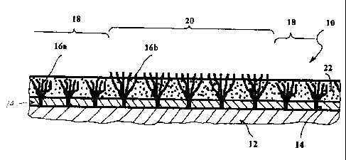
La présente invention concerne une surface de tennis en terre battue synthétique comportant une première zone (18) touffetée de rubans synthétiques (16a) d'une première hauteur, ainsi qu'une deuxième zone (20) touffetée de rubans synthétiques (16b) dont la hauteur est supérieure à celle des rubans de la première zone. Un matériau de remplissage granuleux (22) est appliqué à une profondeur qui recouvre les rubans de la première zone, mais qui laisse dépasser les pointes des rubans de la deuxième zone pour qu'elles soient visibles de manière à former des marquages sur le court d'une couleur différente de celle du matériau de remplissage.


Abrégé anglais


A simulated clay tennis surface has a first region (18) tufted with synthetic
ribbons (16a) of a first height, and a second region (20) tufted with
synthetic ribbons (16b) higher than those of the first region. A granular
infill material (22) is applied to a depth which covers the ribbons in the
first region, but leaves the tips of the ribbons of the second region visible
to form court markings of a contrasting colour to the infill material.

Revendications

Note : Les revendications sont présentées dans la langue officielle dans laquelle elles ont été soumises.


8
CLAIMS:
1. A simulated clay tennis surface, including
a flexible backing sheet;
a playing region of the tennis surface having a plurality of first
synthetic ribbons tufted into and extending generally upwards of
the backing sheet;
a granular infill material filling voids between the first synthetic
ribbons, the infill material being applied to a depth substantially
covering uppermost tips of the first synthetic ribbons; and
a second line region of the tennis surface having a plurality of
second synthetic ribbons tufted into and extending generally
upwards of the backing sheet, the second synthetic ribbons being
of a contrasting colour to a colour of the infill material;
wherein uppermost tips of the second synthetic ribbons are raised relative to
the
playing region and are exposed above the depth of the infill material in the
second
region such that the uppermost tips of the second synthetic ribbons form at
least
one raised court line marking of a simulated clay tennis court.
2. A simulated clay tennis surface according to claim 1, wherein the flexible
backing sheet includes a plurality of backing sheets.
3. A simulated clay tennis surface according to claim 1 wherein the first
synthetic ribbons and the second synthetic ribbons of adjacent portions of the
playing region and the second region are tufted into a continuous flexible
backing
sheet piece.
4. A simulated clay tennis surface according to any one of claims 1 to 3,
wherein the uppermost tips of the second synthetic ribbons are above the depth
of
the infill material in the second region by approximately 1 mm to 3mm.

9
5. A simulated clay tennis surface according to claim 4, wherein the
uppermost tips of the second synthetic ribbons are above the depth of the
infill
material in the second region by approximately 1.5mm.
6. A simulated clay tennis surface according to any one of claims 1 to 5,
wherein the first synthetic ribbons extend upwards of the backing sheet by a
first
distance and the second synthetic ribbons being longer than the first
synthetic
ribbons so that the second synthetic ribbons extend upwards of the backing
sheet
by a second distance which is longer than the first distance.
7. A simulated clay tennis surface according to claim 6, wherein the second
distance is approximately 1mm to 3mm longer than the first distance.
8. A simulated clay tennis surface according to claim 6 or 7, wherein said
second distance is approximately 1.5mm longer than said first distance.
9. A simulated clay tennis surface according to any one of claims 6 to 8,
wherein the infill material is applied to a depth substantially equal to the
second
distance.
10. A simulated clay tennis surface according to any one of claims 1 to 9,
wherein the uppermost tips of the second synthetic ribbons serve as a level
guide
for the infill material.
11. A simulated clay tennis surface according to any one of claims 1 to 10,
wherein the first synthetic ribbons are of a colour substantially matching the
colour of the infill material.
12. A simulated clay tennis surface according to claim 11 wherein the infill
material and the first synthetic ribbons are of a generally terracotta colour.

13. A simulated clay tennis surface according to claim 11 wherein the infill
material and the first synthetic ribbons are of a generally green colour.
14. A simulated clay tennis surface according to any one of claims 1 to 13,
wherein the second synthetic ribbons are of a generally white colour.
15. A simulated clay tennis surface according to any one of claims 1 to 14
wherein the first synthetic ribbons are formed of knit-deknit yarn.
16. A simulated clay tennis surface according to claim 15 wherein the first
synthetic ribbons of the playing region have a stitch rate of less than or
equal to
about 260 stitches per metre.
17. A simulated clay tennis surface according to claim 16 wherein the first
synthetic ribbons of the playing region have a stitch rate of about 210 to 260
stitches per metre.
18. A simulated clay tennis surface according to claim 16 or 17, wherein the
first synthetic ribbons of the playing region have a stitch gauge of about
3/16 to
3/8 inches.
19. A simulated clay tennis surface according to any one of claims 1 to 18,
wherein a pile length of the playing region is between approximately 5 to
12mm.
20. A simulated clay tennis surface according to claim 19, wherein a pile
length of the playing region is between approximately 5mm to 10mm.
21. A method of forming a simulated clay tennis court having a playing area
and line markings, including the steps of:
(a) providing a tennis surface having at least one flexible
backing sheet, a playing region having a plurality of first synthetic
ribbons tufted into and extending generally upwards of the backing

11
sheet, and a second region of the tennis surface having a plurality
of second synthetic ribbons tufted into and extending generally
upwards of the backing sheet, the second synthetic ribbons being of
a contrasting colour to a granular infill material colour;
(b) laying the tennis surface on a supporting surface; and
(c) applying the granular infill material to a depth substantially
covering an uppermost tips of the first synthetic ribbons and
generally below an uppermost tips of the second synthetic ribbons
such that the uppermost tips of the second synthetic ribbons are
exposed to form raised court line markings of the contrasting
colour to the infill material colour.
22. A method according to claim 21, further including a step prior to step (c)
of.
raising the uppermost tips of the second synthetic ribbons such that
the uppermost tips of the second synthetic ribbons are above the
depth of infill material at step (c) by approximately 1 mm to 3mm.
23. A method according to claim 21, further including a step prior to step (c)
of:
raising the uppermost tips of the second synthetic ribbons such that
the uppermost tips of the second synthetic ribbons are above the
depth of infill material at step (c) by approximately 1.5mm.
24. A method according to any one of claims 21 to 23, further including a step
after step (c) of:
levelling the infill material by using the uppermost tips of the
second synthetic ribbons as a level guide for the infill material.
25. A method according to any one of claims 21 to 24, further including in
step (a):

12
tufting the first synthetic ribbons into the backing sheet such that
the first synthetic ribbons extend upwards of the backing sheet by a
first distance; and
providing second synthetic ribbons longer than the first second
synthetic ribbons so that the second synthetic ribbons extend
upwards of the the backing sheet by a second distance which is
longer than the first distance.
26. A method according to claim 25, further including in step (c):
applying and leveling the infill material also to the depth greater
than the first distance but less than or substantially equal to the
second distance.
27. A method according to claim 25 or 26, further including a step prior to
step
(c) of:
providing and tufting the first and second synthetic ribbons such
that the second distance is approximately 1mm to 3mm longer than
the first distance.
28. A method according to claim 25 or 26, further including a step prior to
step
(c) of:
providing and tufting the first and second synthetic ribbons such
that the second distance is approximately 1.5mm longer than the
first distance.

Description

Note : Les descriptions sont présentées dans la langue officielle dans laquelle elles ont été soumises.


CA 02441993 2003-09-17
WO 02/075054 PCT/AU02/00330
1
TENNIS SURFACE
BACKGROUND OF THE INVENTION
The present invention relates to a synthetic sports surface adapted to
simulate a
claycourt tennis surface.
The sport of tennis maybe played on many different court types, for example
lawn,
rubberised surfaces, clay or hardcourt. Each of these surfaces has intrinsic
characteristics of bounce, speed and slide, which differ significantly between
the court
types. Synthetic turf courts simulating lawn are well known.
Such synthetic turf courts are formed as a flexible backing sheet into which
is stitched
(tufted) parallel rows of synthetic ribbons which extend upwards of the
backing sheet
to simulate blades of grass. A backing layer, such as latex, may be applied to
the back
of the backing sheet.
A particulate material, such as layers of sand or crumbed rubber, is used as
an infill
material between the ribbons, to hold the ribbons generally upright and to
provide
resilience to the sports surface. In synthetic turf surfaces, the infill level
extends to a
short distance below the tips of the ribbons, so that the exposed ribbon tips
resemble
the appearance and playing characteristics of grass.
The present applicants have found that it is possible to simulate the playing
characteristics of a clay tennis surface by means of a synthetic turf surface
which is
overfilled so that a layer of the granular infill material covers the tips of
the synthetic
pile. Furthermore, by appropriate colouring the infill material, the
appearance of a
clay court can also by simulated.
The applicants have found however that the techniques and materials used in
conventional synthetic turf may have surprising, and sometimes contrary,
effects when
applied to these simulated clay courts, and therefore that a construction
optimal for a

CA 02441993 2011-07-18
2
conventional synthetic turf court surface may not be optimal for simulated
clay. In
particular, the applicant has found that a relatively long (e.g. 15mm),
straight pile at
close spacing - which would result in a high quality conventional synthetic
turf with
high wear resistance - may provide too much, and slightly directional, slide
if used for
an overfilled, simulated clay surface.
SUMMARY OF THE INVENTION
The present invention aims to provide a simulated clay tennis surface with
good
playing characteristics. The invention also relates to a line construction for
such
courts.
In one form the invention provides a simulated clay tennis surface, including:
a
flexible backing sheet, a playing region of the tennis surface having a
plurality of first
synthetic ribbons tufted into and extending generally upwards of the backing
sheet, a
granular infill material filling voids between the first synthetic ribbons,
the infill
material being applied to a depth substantially covering uppermost tips of the
first
synthetic ribbons; and a second line region of the tennis surface having a
plurality of
second synthetic ribbons tufted into and extending generally upwards of the
backing
sheet, the second synthetic ribbons being of a contrasting colour to a colour
of the
infill material. Where uppermost tips of the second synthetic ribbons are
raised
relative to the playing region and are exposed above the depth of the infill
material in
the second region such that the uppermost tips of the second synthetic ribbons
form at
least one raised court line marking of a simulated clay tennis court.
A further form of the invention provides a method of forming a simulated clay
tennis
court having a playing area and line markings, including the steps of.
(a) providing a tennis surface having at least one flexible backing sheet, a
playing region having a plurality of first synthetic ribbons tufted into and
extending generally upwards of the backing sheet, and a second region of the

CA 02441993 2011-07-18
3
tennis surface having a plurality of second synthetic ribbons tufted into and
extending generally upwards of the backing sheet, the second synthetic
ribbons being of a contrasting colour to a granular infill material colour;
(b) laying the tennis surface on a supporting surface; and
(c) applying the granular infill material to a depth substantially covering an
uppermost tips of the first synthetic ribbons and generally below an uppermost
tips of the second synthetic ribbons such that the uppermost tips of the
second
synthetic ribbons are exposed to form raised court line markings of the
contrasting colour to the infill material colour.
Preferably, raising the uppermost tips of the second synthetic ribbons such
that the
uppermost tips of the second synthetic ribbons are above the depth of infill
material
by approximately lmm to 3mm.
Optionally, tufting the first synthetic ribbons into the backing sheet such
that the first
synthetic ribbons extend upwards of the backing sheet by a first distance and
providing second synthetic ribbons longer than the first second synthetic
ribbons so
that the second synthetic ribbons extend upwards of the backing sheet by a
second
distance which is longer than the first distance.
Preferably, the ribbons of adjacent portions of the first and second regions
are tufted
into the same sheet of flexible backing sheet.
Preferably, the ribbons in at least the first region are knit-deknit ribbons
sufficiently
widely spaced, preferably less than about 260 stitches per metre that upon a
player
sliding on the court surface there is interaction between the infill material
above and
within the pile.
Further forms of the invention are as set out in the appended claims and as
apparent
from the description.

CA 02441993 2011-07-18
4
BRIEF DESCRIPTION OF THE DRAWINGS
Further preferred embodiments will now be described with reference to the
accompanying Figure, in which:
Fig. 1 is a schematic cross-section of a tennis court surface according to a
preferred embodiment.
DETAILED DESCRIPTION OF PREFERRED EMBODIMENTS
With reference to Fig. 1, the tennis surface 10 is laid on a supporting
surface 12 such
as the ground or a substrate of timber, concrete, bitumen or prepared crushed
rock.
The supporting surface is preferably porous to allow water permeability though
the
substrate.
The simulated clay tennis surface has a microporous backing sheet 14 of one or
more
layers, of the type typically used in manufacture of conventional synthetic
turf, e.g. a
woven polypropylene material.

CA 02441993 2003-09-17
WO 02/075054 PCT/AU02/00330
Parallel rows of synthetic ribbons 16 are tufted into the backing layer at a
relatively
open stitch rate of about 210-260 stitches per metre, and a gauge of about
3/16" to
3/8".
5
The surface 10 has first 18 and second 20 regions, forming the playing area
and/or
surrounds, and the court markings respectively.
The ribbons 16a in the first region 18 preferably are relatively short
compared to those
used in conventional high quality tennis surfaces, for example about 5mm to
10mm.
The ribbons 16b in the second region 20 are longer, extending approximately
1mm to
3mm higher than the first region, preferably about 1.5mm, and are of a
contrasting
colour to at least the infill material 20.
The particulate infill material 22, e.g. sand, is of consistent grain size and
is coloured
for example terracotta or green to match the appearance of the court-type
which is
being simulated.
The infill material is applied to a depth which completely covers the pile in
the first
region, which is the main playing area and surrounds of the tennis court, and
levelled
off at or just below the level of the longer ribbons in the second region.
These longer
ribbons therefore have their tips exposed to form the contrasting colour,
preferably
white, visible lines on the tennis court.
In this way, the longer ribbons in the second region may be used as a guide
for
levelling of the infill in the main playing region, and the lines are thereby
pre-formed
in the court. Also, by having the court markings 20 tufted into the same
continuous
piece of backing sheet as the adjacent playing area 18, the cutting and
seaming
required for installation of the court is minimised. The court material may
therefore
be supplied in a conventional roll width, e.g. 3.7m, with the lines pre-
formed. The
court material may thus be supplied as a tennis court kit comprising a
plurality of rolls

CA 02441993 2003-09-17
WO 02/075054 PCT/AU02/00330
6
each with pre-formed line markings corresponding to a specific part of the
court, so
that when the material rolls are laid out side by side and fixed in proper
alignment
they form a tennis court complete with line markings.
The ribbons in the first region are preferably of a colour substantially
matching the
infill, so that slide marks where the ribbons are temporarily uncovered will
also look
like clay court.
The ribbons in at least the first region are preferably formed of knit-deknit
strand,
which is strand which has been deformed by knitting and then unravelling
before
tufting into the backing sheet. When the strand is tufted into the backing
sheet and
cut, the strand reverts to the deformed state so that the tufts twist and curl
in
substantially random directions. Knit-deknit strand is commercially available,
and
known for use in conventional synthetic turf. However, the properties which
make
knit-deknit strand suitable for some applications in conventional turf -
notably the
increased coverage of the backing sheet - are not applicable to the simulated
clay
courts as the strands are completely covered. The ribbons in the second region
preferably have similar characteristics to those in the first region, to
ensure consistent
playing characteristics on all regions of the court.
Surprisingly, however, the applicant has found that knit-deknit strand
provides an
appropriate degree of holding of the infill, allowing the court to exhibit a
similar slide
characteristic to clay, without excessive or directional slip.
Surprisingly also, the applicant has found that the simulated clay surfaces
benefit from
a relatively open stitch rate, for example a 3/16 inch to 3/8 inch gauge and
stitch rate
of about 210-260 stitches per metre. Whilst an open stitch rate would result
in an
inferior quality in a conventional synthetic turf, the applicant has found
that in
simulated clay this promotes frictional interaction between the covering layer
of infill
and the infill trapped in the voids between the ribbons, so that the correct
amount of
slide can be controlled.

CA 02441993 2003-09-17
WO 02/075054 PCT/AU02/00330
7
Furthermore, the Applicant has found the invention allows the use of a
relatively short
pile length without significantly shortening the useful life of the surface as
would be
the case with conventional artificial turf. The Applicant believes that this
extended
life is due to the upper layer of infill material in the overfilled surface
protecting the
ribbons from wear and ultraviolet exposure. Therefore, a pile length of 5-
12mm, most
preferably 5-10mm, may usefully be employed, with consequent reduction in
manufacturing cost, and also reduced transport costs due to the smaller roll
diameter
and lower volume of infill material required.
While particular embodiments of this invention have been described, it will be
evident
to those skilled in the art that the present invention may be embodied in
other specific
forms without departing from the essential characteristics thereof. The
present
embodiments and examples are therefore to be considered in all respects as
illustrative
and not restrictive, and all modifications which would be obvious to those
skilled in
the art are therefore intended to be embraced therein. It will further be
understood that
any reference herein to known prior art does not, unless the contrary
indication
appears, constitute an admission that such prior art is commonly known by
those
skilled in the art to which the invention relates.

Dessin représentatif
Une figure unique qui représente un dessin illustrant l'invention.
États administratifs

2024-08-01 : Dans le cadre de la transition vers les Brevets de nouvelle génération (BNG), la base de données sur les brevets canadiens (BDBC) contient désormais un Historique d'événement plus détaillé, qui reproduit le Journal des événements de notre nouvelle solution interne.

Veuillez noter que les événements débutant par « Inactive : » se réfèrent à des événements qui ne sont plus utilisés dans notre nouvelle solution interne.

Pour une meilleure compréhension de l'état de la demande ou brevet qui figure sur cette page, la rubrique Mise en garde , et les descriptions de Brevet , Historique d'événement , Taxes périodiques et Historique des paiements devraient être consultées.

Historique d'événement

Description Date
Inactive : Périmé (brevet - nouvelle loi) 2022-03-21
Lettre envoyée 2021-09-22
Lettre envoyée 2021-03-22
Représentant commun nommé 2019-10-30
Lettre envoyée 2018-07-19
Inactive : Transfert individuel 2018-07-12
Inactive : Regroupement d'agents 2018-02-05
Inactive : Lettre officielle 2018-02-05
Accordé par délivrance 2012-06-12
Inactive : Page couverture publiée 2012-06-11
Préoctroi 2012-03-26
Inactive : Taxe finale reçue 2012-03-26
Un avis d'acceptation est envoyé 2011-10-25
Lettre envoyée 2011-10-25
Un avis d'acceptation est envoyé 2011-10-25
Inactive : Approuvée aux fins d'acceptation (AFA) 2011-10-19
Lettre envoyée 2011-08-01
Requête en rétablissement reçue 2011-07-18
Modification reçue - modification volontaire 2011-07-18
Exigences de rétablissement - réputé conforme pour tous les motifs d'abandon 2011-07-18
Inactive : Abandon. - Aucune rép dem par.30(2) Règles 2010-07-28
Inactive : Dem. de l'examinateur par.30(2) Règles 2010-01-28
Lettre envoyée 2009-11-02
Exigences de rétablissement - réputé conforme pour tous les motifs d'abandon 2009-11-02
Réputée abandonnée - omission de répondre à un avis sur les taxes pour le maintien en état 2009-03-23
Déclaration du statut de petite entité jugée conforme 2008-02-22
Lettre envoyée 2007-05-04
Toutes les exigences pour l'examen - jugée conforme 2007-03-20
Exigences pour une requête d'examen - jugée conforme 2007-03-20
Requête d'examen reçue 2007-03-20
Inactive : CIB de MCD 2006-03-12
Inactive : Grandeur de l'entité changée 2005-04-05
Inactive : Grandeur de l'entité changée 2004-02-26
Inactive : Page couverture publiée 2003-11-24
Inactive : Inventeur supprimé 2003-11-20
Inactive : Notice - Entrée phase nat. - Pas de RE 2003-11-20
Inactive : Demandeur supprimé 2003-11-20
Inactive : IPRP reçu 2003-10-27
Demande reçue - PCT 2003-10-17
Exigences pour l'entrée dans la phase nationale - jugée conforme 2003-09-17
Demande publiée (accessible au public) 2002-09-26

Historique d'abandonnement

Date d'abandonnement Raison Date de rétablissement
2011-07-18
2009-03-23

Taxes périodiques

Le dernier paiement a été reçu le 2012-03-21

Avis : Si le paiement en totalité n'a pas été reçu au plus tard à la date indiquée, une taxe supplémentaire peut être imposée, soit une des taxes suivantes :

  • taxe de rétablissement ;
  • taxe pour paiement en souffrance ; ou
  • taxe additionnelle pour le renversement d'une péremption réputée.

Les taxes sur les brevets sont ajustées au 1er janvier de chaque année. Les montants ci-dessus sont les montants actuels s'ils sont reçus au plus tard le 31 décembre de l'année en cours.
Veuillez vous référer à la page web des taxes sur les brevets de l'OPIC pour voir tous les montants actuels des taxes.

Historique des taxes

Type de taxes Anniversaire Échéance Date payée
Taxe nationale de base - petite 2003-09-17
TM (demande, 2e anniv.) - générale 02 2004-03-22 2004-02-06
TM (demande, 3e anniv.) - petite 03 2005-03-21 2005-03-17
TM (demande, 4e anniv.) - petite 04 2006-03-21 2006-03-21
Requête d'examen - petite 2007-03-20
TM (demande, 5e anniv.) - petite 05 2007-03-21 2007-03-21
TM (demande, 6e anniv.) - petite 06 2008-03-21 2008-02-22
TM (demande, 7e anniv.) - petite 07 2009-03-23 2009-11-02
Rétablissement 2009-11-02
TM (demande, 8e anniv.) - petite 08 2010-03-22 2010-03-19
TM (demande, 9e anniv.) - petite 09 2011-03-21 2011-03-21
Rétablissement 2011-07-18
TM (demande, 10e anniv.) - petite 10 2012-03-21 2012-03-21
Taxe finale - générale 2012-03-26
TM (brevet, 11e anniv.) - petite 2013-03-21 2013-03-18
TM (brevet, 12e anniv.) - petite 2014-03-21 2014-02-18
TM (brevet, 13e anniv.) - petite 2015-03-23 2015-01-06
TM (brevet, 14e anniv.) - petite 2016-03-21 2016-01-06
TM (brevet, 15e anniv.) - petite 2017-03-21 2016-12-01
TM (brevet, 16e anniv.) - petite 2018-03-21 2017-11-22
Enregistrement d'un document 2018-07-12
TM (brevet, 17e anniv.) - générale 2019-03-21 2019-02-27
TM (brevet, 18e anniv.) - générale 2020-03-23 2020-02-26
Titulaires au dossier

Les titulaires actuels et antérieures au dossier sont affichés en ordre alphabétique.

Titulaires actuels au dossier
FIELDTURF, INC.
Titulaires antérieures au dossier
GARY WAYNE WATERFORD
Les propriétaires antérieurs qui ne figurent pas dans la liste des « Propriétaires au dossier » apparaîtront dans d'autres documents au dossier.
Documents

Pour visionner les fichiers sélectionnés, entrer le code reCAPTCHA :


Pour visualiser une image, cliquer sur un lien dans la colonne description du document. Pour télécharger l'image (les images), cliquer l'une ou plusieurs cases à cocher dans la première colonne et ensuite cliquer sur le bouton "Télécharger sélection en format PDF (archive Zip)" ou le bouton "Télécharger sélection (en un fichier PDF fusionné)".

Liste des documents de brevet publiés et non publiés sur la BDBC .

Si vous avez des difficultés à accéder au contenu, veuillez communiquer avec le Centre de services à la clientèle au 1-866-997-1936, ou envoyer un courriel au Centre de service à la clientèle de l'OPIC.


Description du
Document 
Date
(aaaa-mm-jj) 
Nombre de pages   Taille de l'image (Ko) 
Description 2003-09-16 7 312
Dessins 2003-09-16 1 12
Revendications 2003-09-16 4 154
Dessin représentatif 2003-09-16 1 12
Abrégé 2003-09-16 1 54
Revendications 2011-07-17 5 156
Description 2011-07-17 7 285
Dessins 2011-07-17 1 23
Dessin représentatif 2012-05-13 1 21
Avis d'entree dans la phase nationale 2003-11-19 1 188
Rappel de taxe de maintien due 2003-11-23 1 109
Rappel - requête d'examen 2006-11-21 1 118
Accusé de réception de la requête d'examen 2007-05-03 1 176
Courtoisie - Lettre d'abandon (taxe de maintien en état) 2009-05-18 1 172
Avis de retablissement 2009-11-01 1 162
Courtoisie - Lettre d'abandon (R30(2)) 2010-10-19 1 165
Avis de retablissement 2011-07-31 1 171
Avis du commissaire - Demande jugée acceptable 2011-10-24 1 163
Courtoisie - Certificat d'enregistrement (document(s) connexe(s)) 2018-07-18 1 125
Avis du commissaire - Non-paiement de la taxe pour le maintien en état des droits conférés par un brevet 2021-05-02 1 535
Courtoisie - Brevet réputé périmé 2021-10-12 1 539
PCT 2003-09-16 3 112
PCT 2003-09-16 4 216
Taxes 2008-02-21 1 19
Correspondance 2012-03-25 1 57
Courtoisie - Lettre du bureau 2018-02-04 1 32