Note : Les descriptions sont présentées dans la langue officielle dans laquelle elles ont été soumises.
CA 02442055 2003-09-22
WO 02/099188 PCT/US02/06520
1
SHOE PRESS BELT WITH SYSTEM
FOR DETECTING OPERATIONAL PARAMETERS
Field of the Invention
The present invention relates generally to nip presses, and more particularly
to
shoe presses.
Background of the Invention
In the conventional fourdrinier papermaking process, a water slurry, or
suspension, of cellulosic fibers (known as the paper "stock") is fed onto the
top of the
upper run of an endless belt of woven wire and/or synthetic material that
travels
between two or more rolls. The belt, often referred to as a"forming fabric,"
provides
a papermaking surface on the upper surface of its upper run which operates as
a filter
to separate the cellulosic fibers of the paper stock from the aqueous medium,
thereby
forming a wet paper web. The aqueous medium drains through mesh openings of
the
forming fabric, known as drainage holes, by gravity or vacuum located on the
lower
surface of the upper run (i.e., the "machine side") of the fabric.
After leaving the forming section, the paper web is transferred to a press
section of the paper machine, where it is passed through the nips of one or
more
presses (often roller presses) covered with another fabric, typically referred
to as a
"press felt." Pressure from the presses removes additional moisture from the
web; the
moisture removal is often enhanced by the presence of a "batt" layer of the
press felt.
The paper is then transferred to a dryer section for further moisture removal.
After
drying, the paper is ready for secondary processing and packaging.
Over the last 25 or 30 years, a "shoe press" has been developed for the press
section of the papermaking machine. A shoe press includes a roll or similar
structure
that mates with a "shoe" of an opposed roll or press structure; the surface of
the shoe
is somewhat concave and approximates in curvature the convex profile of the
mating
roll. This arrangement can increase the width of the nip in the direction of
paper
travel, thereby enabling greater amounts of water to be removed therein.
Endless belts or blankets have traditionally been used in shoe press
operations.
The belt overlies and contacts the shoe of the press; in turn, the press felt
overlies the
shoe press belt, and the paper web overlies the press felt. The shoe press
belt and
press felt travel through the nip and, in doing so, convey the paper web
through the
CA 02442055 2003-09-22
WO 02/099188 PCT/US02/06520
nip. The press felt travels over a set of rollers arranged around the shoe. In
older
embodiments, shoe press belts were also driven by sets of drive rollers
arranged
around the shoe. In some newer configurations, however, the shoe press belt is
clamped or otherwise fixed to the edges of circular head plates located on
either end
of the shoe, such that rotation of the head plates causes the shoe press belt
to. rotate
and travel through the nip.
Given the performance requirements, a shoe press belt should be sufficiently
flexible to pass around the drive rollers or head plates and through the shoe
and
sufficiently durable to withstand the repeated application of pressure within
the nip.
Because of these performance parameters, most endless belts are formed
entirely or
predominantly of a polymeric material (often polyurethane). Many shoe press
belts
also include reinforcing fibers or a reinforcing fabric between or embedded in
polymeric layers. Also, shoe press belts may be configured to encourage water
to
pass from the paper web. To this end, some shoe press belts have grooves or
blind-
drilled holes in the surface adjacent the press felt that serve to vent water
from the
paper that is exiting the press felt.
As the paper web is conveyed through the nip, it can be very important to
understand the pressure profile experienced by the paper web. Variations in
nip
pressure can impact the amount of water drained from the web, which can affect
the
ultimate sheet moisture content, thickness, and other properties. Excessive
nip
pressures can cause crushing or tearing of the web. Of course, in a shoe press
the
pressure typically varies at different locations in the nip, both along and
transverse to
the direction of paper travel, and can also vary over time. As a result, it
would be
desirable to have a reliable technique and apparatus for determining the
pressure
distribution and area of the nip in a shoe press.
Other properties of a shoe press belt can also be important. For example, the
stress and strain experienced by the belt, both in the machine direction and
the cross
machine direction, can provide information about the durability and
dimensional
stability of the belt. In addition, the temperature profile of the belt can
assist in
identifying potential problem areas of the belt. As such, it would be
desirable to have
a reliable technique and apparatus for determining these properties of a shoe
press
belt.
2
CA 02442055 2007-11-09
77203-79
Summary of the Invention
The present invention is directed to a shoe press
and associated belt that can determine operating parameters
within the nip of a shoe press. A shoe press of the present
invention comprises: a first member; a second member; a
substantially cylindrical belt; and a processing unit. The
first member has a convex pressing surface. The second
member includes a shoe with a concave pressing surface
substantially complimentary to the convex pressing surface.
The second member further includes a pair of substantially
circular head plates rotatably mounted on axially opposed
ends thereof. The belt is fixed to, extends between, and is
rotatable with the head plates such that a portion of the
belt passes between the convex pressing surface and the
concave pressing surface. The belt includes embedded
therein a communications cable having a plurality of sensors
configured to generate signals responsive to an operating
parameter of the shoe press. The processing unit is in
communication with the communications cable and processes
signals generated by the sensors. Thus, signals generated
by the sensors and processed by the processing unit
represent conditions (particularly pressure, nip width,
temperature, strain and stress) within the nip of the shoe
press that can be displayed and understood by an operator.
In one embodiment, the belt comprises: a
substantially cylindrical inner polymeric layer having a
first longitudinal axis and a radially inner surface; a
substantially cylindrical outer polymeric layer having a
second longitudinal axis that is substantially collinear
with the first axis and a radially outer surface; a
substantially cylindrical fabric layer sandwiched between
the inner and outer polymeric layers; and a communications
cable having a plurality of sensors configured to detect an
3
CA 02442055 2007-11-09
77203-79
operating parameter of a shoe press. The radially inner and
radially outer surfaces define a belt thickness, and the
sensing fiber extends within the belt thickness.
Preferably, the inner and outer polymeric layers are
polyurethane, and the sensing fiber is an optical fiber that
travels in a single helix along the length and circumference
of the belt.
In another aspect, the invention provides a belt
for a shoe press, comprising: a substantially cylindrical
polymeric layer having a first longitudinal axis, a radially
inner surface, and a radially outer surface, said radially
inner and said radially outer surfaces defining a belt
thickness; and a communications cable having a plurality of
sensors configured to detect an operating parameter of the
shoe press, said communications cable extending within and
embedded in said belt thickness.
Brief Description of the Figures
Figure 1 is an end view of a shoe press of the
present invention.
Figure 2 is a front section view of the lower roll
and shoe press belt of the shoe press of Figure 1.
3a
CA 02442055 2003-09-22
WO 02/099188 PCT/US02/06520
Figure 3 is a perspective view of the shoe press belt of Figure 1 with the
outer
polymeric layer removed to reveal the sensing fiber.
Figure 4 is an enlarged end view of the roll and shoe press belt of Figure 1
with a data collection system connected thereto illustrated schematically.
Figure 5 is an alternative embodiment of a shoe press belt of the present
invention with the outer polymeric layer removed to reveal the sensing fiber.
Figure 6 is another embodiment of a shoe press belt of the present invention
with the outer polymeric layer removed to reveal the sensing fiber.
Figure 7 is yet another embodiment of a shoe press belt of the present
invention with the outer polymeric layer removed to reveal the sensing fiber.
Figure 8 is a greatly enlarged end section view of the shoe press belt of
Figure 1.
Figure 9 is a greatly enlarged top section view of the shoe press belt of
Figure
I with portions of the outer polymeric layer and fabric layer removed.
Figure 10 is an alternative embodiment of a shoe press belt of the present
invention configured for sensing machine direction and cross machine direction
strain
or stress.
Detailed Description of the Invention
The present invention will now be described more fully hereinaiter, in which
preferred embodiments of the invention are shown. This invention may, however,
be
embodied in different forms and should not be construed as limited to the
embodiments
set forth herein. Rather, these embodiments are provided so that this
disclosure will be
thorough and complete, and will fully convey the scope of the invention to
those skilled
in the art. In the drawings, like numbers refer to like elements throughout.
Thicknesses
and dimensions of some components may be exaggerated for clarity.
Referring now to Figures 1 and 2, a shoe press, designated broadly at 20, is
illustrated therein. The shoe press 20 includes a lower roll 22 and a mating
upper roll 24
that define therebetween a nip 25 through which a web or sheet, such as a
paper web 37,
can travel. Each of the lower and upper rolls 22, 24 defines a respective axis
Al, A2; the
axes Al, A2 are essentially parallel with one another and substantially
perpendicular to
the direction MD that the web 37 travels. As can be seen in Figure 1,
illustratively and
preferably press felts 35, 36 are positioned between the lower and upper rolls
22, 24; the
4
CA 02442055 2003-09-22
WO 02/099188 PCT/US02/06520
press felts 35, 36 are driven around respective sets of drive rollers 35a, 36a
by the lower
and upper rolls 22, 24. The web 37 is conveyed by and between the press felts
35, 36.
Referring again to Figures 1 and 2, the lower rol122 includes a beam 26 that
extends parallel to the axis Al. At either end, the beam 26 includes a round
shaft 28 that
engages and is supported by a bracket 30. A shoe 32 with a concave pressing
surface 33
extends upwardly from the beam 26. The shoe 32 is mounted onto the beam 26
such
that it can be controllably biased upwardly; the biasing of the shoe 32 can be
accomplished with, for example, a hydraulic system (not shown). A circular
head plate
34 is rotatably mounted on each shaft 28 spaced apart from the end of the shoe
26.
Bearings 35 enable the head plates 34 to be rotated on the shaft 28.
A substantially cylindrical shoe press belt 40 is mounted about the perimeter
of
each head plate 34 such that its longitudinal axis is substantially parallel
with the axis
Al. The shoe press belt 40 is fixed to the head plates 34 (by clamping or the
like) such
that, as the head plates 34 rotate about the shafts 28, they cause the shoe
press belt 40 to
rotate also. Typically, the shoe press belt 40 is between about 40 and 84
inches in
diameter and between about 120 and 480 inches in length.
As shown in Figure 1, the lower and upper rolls 22, 24 are positioned relative
to
each other so that the upper ro1124 causes the shoe press belt 40 to deflect
from a
cylindrical configuration and conform to the configuration of the pressing
surface 33 of
the shoe 32. The pressing surface 33 of the shoe 32 is shaped to be
substantially
complimentary to the convex profile of the upper roll 24, with the result that
the nip 25
has significant width and is extended in the direction MD (see Figure 2,
wherein the
width of the nip 25 is designated (x; this dimension is typically between
about 8 and
12 inches). Both the shoe 32 and the upper ro1124 can be adjusted to control
the
magnitude and distribution of the pressure in the nip 25; in particular, the
shoe 32 may
be pivotable about an axis parallel to axis Al that enables the pressure to be
adjusted
along the direction of web travel MD. As the shoe press belt 40"rotates with
the head
plates 34, portions thereof are deflected by the contact surface 24a of the
upper ro1124
to contact the contact surface 33 of the shoe 32.
Those skilled in this art will recognize that the present invention may be
suitable for shoe presses of other configurations. For example, the lower
ro1122 may
include a fixed shaft and a hydraulic shoe (such as that available from Voith
Sulzer
Papiermachschinen GmbH, Heidenheim, Germany under the tradename FLEXONlP),
5
CA 02442055 2007-11-09
77203-79
or may be replaced with a shoe alone, wherein the shoe press belt is n ided
across the
shoe by a set of drive rollers. The upper roll 24 may be hydraulically
supported (as is
the case with the FLEXONIP press mentioned above), may include an adjustable
convex shoe (such as that available from Voith Sulzer, Heidenheim, Germany,
under
the tradename INTENSA), or may lack adjustability. Also, the lower and upper
members may be oriented such that the concave pressing surface of the shoe is
presented by the upper member of the shoe press and the convex pressing
surface is
presented by the lower member of the shoe press. These and other
configurations of
suitable shoe presses are described and illustrated in Joint Textbook
Committee of the
Paper Industry, Pulp a71d Paper Manufacture, Vol. 7, 267-70 (Third Edition,
1991).
Alternative configurations should include a shoe with a concave pressure
surface that
is adjustable and a mating structure (such as a roll or opposed convex shoe)
that form
a nip tlirough which a shoe press belt travels:
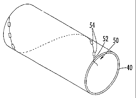
Referring now to Figures 3 and 4, the shoe press 20 includes a sensor
assembly 50 that can detect operational parameters in the nip 25. The sensor
assembly 50 includes a fiber 52 disposed within the shoe press belt 40. The
fiber 52
has a series of sensors 54 along its length configured to respond to one or
more
operating parameters of interest in the nip 25, such as the magnitude and
distribution
of pressure, temperature, strain, stress, and nip width, and generate signals
proportionate to such pressure. Those skilled in this art will recognize that
the fiber
52 can be any type of communications cable in which information generated by
the
sensors 54 can pass.
Exemplary sensors 54 include fiber optic sensors, piezoelectric sensors,
piezoresistive sensors, strain gage sensors, and the like, with fiber optic
sensors being
preferred. Clearly, suitable sensors should be sufficiently durable to
withstand the
operating pressures and other environmental conditions experienced during
operation
of the shoe press belt 40 and sufficiently sensitive to respond accurately
based on
those operating conditions. Also, the fiber 52 or other communications cable
should
be selected to be compatible with the selected sensor type; for example, if
fiber optic
sensors are to be used, the fiber 52 should be an optical fiber. Preferred
fiber optic
sensors include microbend-type sensors, with particularly preferred sensors
being
described in U.S. Patent No. 6, 429,421.
Such sensors are typically installed every 5
to 17 inches of circumference of the belt, so an exemplary shoe press belt 40
having a
6
CA 02442055 2007-11-09
77203-79
circumference of 190 inches may have between about 10 and 40 sensors 54.
Illustratively and preferably, the sensors 54 are positioned substantially
equidistant
from each other along the length of the fiber 52, but other configurations,
such as
those in which sensors are more concentrated in one or more areas of
particular
interest, may also be used.
The fiber 52 is operatively connected to a processing unit 56 mounted on the
outer surface of one of the head plates 34. The processing unit 56 receives
signals_ .
generated by the sensors 54 as they pass through the nip 25. The processing
unit 56
includes a signal transmitter 58 that is in communication with a signal
receiver 62
mounted remotely from the shoe press 20. The signal receiver 62 is hard-wired
to a
personal computer 64 or other data processing device (such as the distributive
control
system of a paper mill) that can process signals from the transmitter 58 into
usef-ul,
easily understood information. It is preferred that a wireless communication
mode,
such as RF sign.aling, be used to transmit the data from the processing unit
56 to the
receiver 62. Suitable exemplary processing units are discussed in U.S. Patent
No.
5;562,027 to Moore; other exemplary processing units include slip ring type
electrical
contacts.
As illustrated in i~'igure 4, the fiber 52 may be disposed in the shoe press
belt
40 in a helical configuration as it extends along the axis Al. The single
helix i.e the
fiber travels essentially one circumference of the belt 40 as it travels the
length of the
belt 40) of the fiber 52 places each sensor 54 at a position that is not
aligned either
axially or circumferentially with any other sensor 54. Such positioning can
ensure
that only one sensor 54 is located within the nip 25 at any one time, so
transmission
and receipt of data can be simplified i.e. no multiplexer is reqiuired for
data
collection and processing).
Alternative configurations for the fiber 52 include those in which the fiber
extends axially only (see fiber 52a in Figure 5), the fiber extends only
circumferentially (see fiber 52b in Figure 6), and the fiber extends over a
somewhat
random pattern (see fiber 52c in Figure 7). It should also be understood that,
although the sensors 54 on the fibers 52a, 52b, 52c are essentially equally
spaced
along the length~of the nip and the circumference of the shoe press belt 40,
sensors
that are unevenly spaced axially and/or circumferentially may also be
employed.
Those skilled in this art will appreciate that other configurations of the
fiber may also
be suitable for use with the present invention. Further, those skilled in this
art will
7
CA 02442055 2007-11-09
77203-79
also appreciate that multiple fibers or commuziications cables containing
sensors may
also be employed (see Figure 10). Moreover, a fiber or communications cable
containing only a single sensor (such as fibers 52d, 522e shown in Figure 10)
may
also be employed with the present invention; single sensor fibers like 52d,
52e may be
particularly siiitable for detection of axial strain in the belt (in the case
of fiber 52d
and sensor 54d) or circumferential strain (in the case of fiber 52e and sensor
54e).
Alternatively, these sensors may be multiplexed on a single fiber or cable, or
multiple
sensors of a common type (for example, circumferential strain sensors) may be
connected with one cable and sensors of another type (for example, axial
strain
sensors) may be connected with a second cable.
Referring now to Figures 8 and 9, illustratively and preferably the shoe press
belt 40 includes an inner layer 42 (typically formed of a polymer such as
polyurethane), a fabric layer 44, and an outer layer 46 (like the inner layer
42, the
outer layer 46 is typically formed of a polymer such as polyurethane).
Typically, the
material comprising the inner and outer layers 42, 46 will be the same, but it
need not
be. An exemplary material for use in the inner and outer layers 42, 46 is a
polyurethane material having a Pusey & Jones hardness value of between about 5
and
15. The inner layer 42 preferably has a thickness dimension of between about
0.025
and 0.100 inches, and the outer layer 46 preferably has a thiclmess dimension
of
between about 0.025 and 0.250 inches. It may also be desirable for the outer
layer 46
to include grooves, blind-drilled holes, or other recesses to vent water from
the paper
web and press felt during operation; exemplary structures are illustrated in
U.S. Patent
Nos. 4,559,258 to Kiuchi and 6,030,503 to Matuschcyzk,
The fabric layer 44 is included in the shoe press belt 40 to provide
reinforcement in the machine and cross-machine directions. As used herein, the
fabric layer 44 is intended to encompass both woven fabrics (such as those
illustrated
in U.S. Patent No. 5,196,092 to Stigberg)_ and reinforcing structures having
circumferentially-extending members (which may or may not be accompanied by
axially-extending members), such as the constructions described and
illustrated in
U.S. Patent No. 5,525,194 to Jermo.
In the illustrated configuration, the fiber 52 overlies the fabric layer 44
(typically such that the fiber 52 is somewhat embedded in the outer layer 46).
In
8
CA 02442055 2007-11-09
77203-79
some embodiments the fiber 52 may be interwoven with the fabric layer 44. For
example, the fiber 52 may pass above and below yarns in the fabric layer 44 in
a
repeating pattern such that the sensors 54 are presented to the nip at the
same depth
below the outer surface of the outer layer 46. In certain embodiments the
fiber 52
may even replace or accompany one or more yams within the weave pattern of the
fabric layer 44; this is particularly true for belts in which the fiber
extends only axially
or only circumferentially.
The shoe press belt 40 can be constructed by any manner lmown for the
construction of shoe press belts, such as casting, molding, extrusion, or the
like. In
one embodiment, the shoe press belt 40 may be cast over a mandrel, which may
include a removable or erodable material such as that described in U.S. Patent
No.
6,070,107 to Lombardi et al. Removal of the erodable material after
construction of
the shoe press belt 40 (by, for example, dissolving the material in a suitable
solvent)
can create a aap between the shoe press belt 40 and the mandrel, thereby
facilitating
removal of the shoe press belt 40 therefrom.
A shoe press belt 40 that includes a sensor assembly as described above can
provide real-time information about operational parameters in the nip, such as
the
magnitude and distribution of pressure, nip width, strain, stress, and
temperature.
Such information can enable an operator to adjust the shoe press 20 as desired
for the
papermaking operation at hand. For example, it may be desirable to adjust the
shoe
32 so that pressure within the nip 25 remains at a certain magnitude. As
another
example, it may be desirable to adjust the shoe 32 so that the peak pressure
experienced in the nip 25 is located toward the "downstream" end of the nip 25
rather
than in the center, as doing so can improve the quality of paper formed
therein.
It is also contemplated that a belt of the present invention may be suitable
for
other uses. These may include, for example, calendering belts for papermaking
machines.
The foregoing is illustrative of the present invention and is not to be
construed
as limiting thereof. Although exemplary embodiments of this invention have
been
9
CA 02442055 2003-09-22
WO 02/099188 PCT/US02/06520
described, those skilled in the art will readily appreciate that many
modifications are
possible in the exemplary embodiments without materially departing from the
novel
teachings and advantages of this invention. Accordingly, all such
modifications are
intended to be included within the scope of this invention as defined in the
claims.
The invention is defined by the following claims, with equivalents of the
claims to be
included therein.