Note : Les descriptions sont présentées dans la langue officielle dans laquelle elles ont été soumises.
CA 02442216 2010-09-15
1
APPARATUS FOR CONNECTING FLUID CONDUITS
This invention is in the field of fluid conduits such as are used to carry
liquids and gases,
and in particular an apparatus for connecting such conduits together or to
various fittings
in a conduit network.
BACKGROUND
Sections of fluid conduit must be connected together, or to other fittings in
a conduit
network to carry gases and liquids without leaking from the network. The fluid
pressure
varies from low pressure lines, such as sewage lines where the pressure is
essentially
atmospheric pressure, to higher pressure water lines and the like, up to very
high pressure
industrial lines where the pressure is 10,000 pounds per square inch (psi) or
more.
Conventional conduit connections are made using a gasket that is essentially
clamped and
squeezed between hollow members attached to each conduit. The clamping force
is
exerted by bolts in a typical flange connection, by a threaded configuration
on a typical
pipe union, and like apparatuses.
For example in a typical flange connection, conventional gaskets are made from
a
material that is softer than the flange material, typically metal, plastic,
rubber, or the like.
Sealing of the connection is accomplished by clamping the flanges very tightly
together
so that the gasket is squashed between the two flanges. Typically the clamping
force is
provided by several bolts through corresponding holes around the flanges. To
ensure
proper sealing the bolts must be tightened evenly to a high torque. The
flanges must be
strong enough to resist distortion under the clamping forces, and as a result
such flanges
are commonly heavy, costly, and cumbersome, especially for high pressure
conduits.
CA 02442216 2010-09-15
2
Similarly in a pipe union the threaded members are tightened to squeeze the
sealing
faces. In some unions of this type a gasket is used between the faces, while
in others no
gasket is present and the metal faces alone provide the seal when squeezed
together.
Conduit networks can comprise a large number of connections. Significant
longitudinal
forces are exerted on the conduits when the conventional connections are
tightened to
exert the required clamping force. These forces are transferred through the
conduit
network from each such connection, causing stress on.the entire network. The
network
must be designed to accommodate these forces, and careful installation is
required to
avoid excessive stress and resulting failure of components.
A prior art conduit coupling disclosed in United States Patent Number
2,491,004 to
Graham uses the pressure inside the conduit to force a gasket into engagement
with a
housing to seal a pipe coupling.
In some applications it is desired to have one conduit section or fitting
swivel or rotate
with respect to the next. It is known to use springs in such applications to
urge a
stationary seal against another rotating seal with sufficient force to prevent
leakage
between the two. Such swivel couplings are disclosed for example in United
States
Patent Number 2,927,805 to Faccou, and 3,057,646 to Brumagin.
SUMMARY OF THE INVENTION
It is an object of the present invention to provide an apparatus for
connecting conduits
together, or to other conduit network components that overcomes disadvantages
of the
prior art connections. It is a further object of the present invention to
provide such an
apparatus that requires reduced clamping forces to connect the conduits
together. It is a
further object of the present invention to provide such an apparatus that
reduces
longitudinal forces exerted on connected conduits.
CA 02442216 2010-09-15
3
It is a further object of the present invention to provide such an apparatus
that uses the
pressure of fluid inside the conduits to exert a scaling force on a gasket
sealing the
connection between the conduits.
The invention provides, in one embodiment, apparatus for connecting first and
second
conduits to carry a fluid under pressure comprising a first face attached
around an open
end of the first conduit; a pocket face attached around an open end of the
second conduit
and defining a pocket; wherein the first face is fastened to the pocket face
such that the
first face is substantially perpendicular to walls of the pocket and adjacent
to an open end
of the pocket; a gasket member slidingly engaged in the pocket and defining a
passageway through a central portion thereof, the gasket member having a
gasket face
adjacent and substantially parallel to the first face and an opposite pressure
face inside the
pocket; at least one bias element exerting a bias force on the gasket member
toward the
first face; a pocket seal sealing an outer periphery of the gasket member to
the walls of
the pocket; a main gasket between the gasket face of the gasket member and the
first
face; wherein the pressure face of the gasket member is exposed to fluid
carried by the
conduits and has an area that is greater than an area of the gasket face
between the main
gasket and the passageway through the gasket member.
In a second embodiment the invention provides an apparatus for connecting
first and
second conduits to carry a fluid under pressure comprising a first flange
adapted for
attachment to an open end of the first conduit; a pocket flange adapted for
attachment to
an open end of the second conduit and defining a pocket;wherein the first
flange is
adapted to be fastened to the pocket flange such that a face of the first
flange is
substantially perpendicular to walls of the pocket and adjacent to an open end
of the
pocket; a gasket member slidingly engaged in the pocket and defining a
passageway
through a central portion thereof, the gasket member having a gasket face
adjacent and
substantially parallel to the face of the first flange when the first flange
is fastened to the
CA 02442216 2010-09-15
4
pocket flange, and an opposite pressure face inside the pocket; at least one
bias element
operative to exert a bias force on the gasket member toward the open end of
the pocket; a
pocket seal operative to seal an outer periphery of the gasket member to the
walls of the
pocket; a main gasket adapted to be positioned between the gasket face of the
gasket
member and the face of the first flange; wherein the pressure face of the
gasket member
is exposed to fluid carried by the conduits and has an area that is greater
than an area of
the gasket face between the gasket and the passageway through the gasket
member.
Once the conduits are pressurized with fluid, pressure inside the connection
forces the
main gasket on the face of the gasket member against the face of the first
flange. Higher
pressure exerts a greater force with the result that the seal is maintained
for a wide range
of pressures.
Installation is simplified since the high torque and even clamping force
required by
conventional connections is not required by the apparatus of the invention.
Stress on the
conduit network is reduced since clamping forces and the resulting
longitudinal forces
exerted on the conduits are reduced. Installation and design are simplified.
The invention also provides an apparatus for sealing two conventional flanges
together,
thus providing a substitute for a conventional soft gasket.
DESCRIPTION OF THE DRAWINGS:
While the invention is claimed in the concluding portions hereof, preferred
embodiments
are provided in the accompanying detailed description which may be best
understood in
conjunction with the accompanying diagrams where like parts in each of the
several
diagrams are labeled with like numbers, and where:
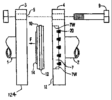
Fig. 1 is a side view of an apparatus of the invention joining two conduits;
CA 02442216 2010-09-15
Fig. 1 A is a schematic detail view of the spring bias elements;
Fig. 2 is a top view of the gasket member of the apparatus of Fig. 1;
5
Fig. 3 is a bottom view of the gasket member;
Fig. 4 is a top view of an alternate apparatus to provide a seal between two
conventional flat flanges;
Fig. 5 is a schematic cross-section through line 5-5 in Fig. 4.
DETAILED DESCRIPTION OF THE ILLUSTRATED EMBODIMENTS:
Fig. 1 illustrates an apparatus of the present invention for connecting
conduits 1 and 2 to
carry a fluid under pressure. The apparatus comprises a first flange,
illustrated as flat
flange 3 with a flat face 5 attached around an open end of the first conduit
1. A pocket
flange 4 is attached around an open end of the second conduit 2 and has a
pocket face 11
that defines a pocket 7. The same connection can be made where one of the
flanges 3, 4
is attached to a conduit that is incorporated in a T-fitting, an elbow, or any
like
component of a conduit network.
The first face 5 is adapted to be fastened to the pocket face 11 with bolts 9
or the like
such that the first face is 5 substantially perpendicular to walls 7W of the
pocket 7 and
adjacent to an open end of the pocket 7. A threaded union, or similar known
mechanism
for holding the flanges together could be used as well. A gasket member 10 is
slidingly
engaged in the pocket 7 and defines a passageway through a central portion
thereof to
allow fluid to flow through the connection. The gasket member 10 has a gasket
face 13
CA 02442216 2010-09-15
6
adjacent and substantially parallel to the first face 5 and the gasket member
10 has an
opposite pressure face 15 inside the pocket 7.
Bias elements, illustrated as springs 20, exert a bias force on the gasket
member 10
toward the first face 5. A pocket seal, illustrated as outer o-ring 12, seals
the outer
periphery of the gasket member 10 to the walls 7W of the pocket 7. A main
gasket,
illustrated as inner o-ring 14, lies between the gasket face 13 of the gasket
member 10
and the first face 5.
Gasket member 10, as best seen in Figs. 2 and 3, is an annular ring of metal,
or a like
hard material, with a groove around the periphery thereof to accommodate the
outer o-
ring 1.2, and a groove in gasket face 13 to accommodate the inner o-ring 14.
The
opposite pressure face 15 of the gasket member 10, illustrated in Fig. 3 is
typically flat.
Flat flange 3 has a flat face 5 that bears against the inner o-ring 12. Pocket
flange 4
defines a pocket 7 such that the gasket member 10 slides into the pocket 7
with the outer
o-ring 12 sealing against the walls of the pocket 7. The flanges 3, 4 are
clamped together
with bolts 9.
Conventional gasket members are made from a material that is softer than the
flange
material, typically metal, plastic, rubber, or the like. Sealing of the
connection is
accomplished by tightening the bolts to a high torque so that the gasket is
squashed
between the two flanges. The bolts must also be tightened evenly to ensure
proper
sealing.
Sealing of the conduit connection of the invention does not depend on a high
torque on
the bolts 9 exerting a large clamping force. In fact the clamping force is not
translated to
the gasket member 10 at all, since the gasket member 10 slides in the pocket
7. The seal
of the invention is accomplished initially with bias elements, illustrated as
springs 20,
CA 02442216 2010-09-15
7
pushing against the pressure face 15 of the gasket member 10 and causing the
gasket
member 10 to slide in the pocket 7 and thus force the inner o-ring 14 against
the flat face
of the flat flange 3. The inner o-ring 14 seals against the flat face 5 of the
flat flange 3,
and the outer o-ring 12 seals against the walls of the pocket 7, thereby
sealing the
5 connection.
Fig. IA schematically illustrates the seating of a spring 20 in a recess 22 in
the bottom of
the pocket 7 in pocket flange 4. The bias force could also be provided by
various other
spring configurations, resilient pads, or similar bias elements as are known
in the art.
During start up, the seal between inner o-ring 14 and flat face 5 is
maintained by the
springs 20. As the pressure in the conduits 1, 2 builds, that pressure exerts
a
correspondingly increasing force urging the gasket member 10 towards the flat
face 5 of
the flat flange 3, as described below.
Between the outer and inner o-rings 12, 14 on the inside of the seal, the
pressure HP is
that of the fluid inside the connected conduits 1, 2. Between the o-rings 12,
14 on the
outside of the seal, the pressure is that of the atmosphere surrounding the
connection AP,
typically much lower than the pressure HP inside the conduits 1, 2. Thus the
pressure
face 1.5 of the gasket member 10 is exposed to fluid carried by the conduits
1,2 and has
an area that is greater than an area of the gasket face 13 between the main
gasket, inner o-
ring 14, and the passageway l OB through the gasket member B.
Thus the pressure HP is being exerted on that portion of the gasket member 10
indicated
by Al on the gasket face 13, and A2 on the pressure face 15. This is the area
between
the o-rings 12, 14 that is inside the connection, extending from the inner
ring 14 to the
inside passageway l OB of the gasket member 10 (indicated by Al), along the
walls of the
passageway l OB, and across the opposite pressure face 15 to the outer edge of
the gasket
member 10 (indicated by A2) and then along the outer wall to the outer o-ring
12.
CA 02442216 2010-09-15
8
That portion of the gasket member 10 that is outside the seal is exposed to
lower
atmospheric pressure AP. The outside portion extends from the outer o-ring 14
along the
wall to the gasket face 1.3 and along the gasket face 13 from the outer edge
thereof to the
inner o-ring 12 (indicated by A3).
The force exerted on the pressure face 15 of the gasket member 10 in direction
F is a
product of the total area A2 of the pressure face 15 times the pressure HP,
plus whatever
force is exerted by the springs 20. The force exerted on the gasket face 13 of
the gasket
member 10 in the direction opposite to F is a product of the area Al of one
portion of the
gasket face 13 times the pressure HP, plus the area A3 of the other portion of
the gasket
face 13 times the atmospheric pressure AP.
The area A2 is approximately equal to the sum of the areas Al and A3,
discounting the
width of the inner o-ring 14. After assembly and prior to pressurizing the
connection, the
pressure inside HP and outside AP is the same, and the forces resulting from
pressure are
substantially equal. The force in direction F is then equal to the force of
the springs 20.
The force of the springs 20 is designed to provide sufficient force to
maintain the seal via
inner o-ring 14 between the gasket member 10 and the flat face 5 of the flat
flange 3
during start up.
As the pressure HP builds, it can be seen that the force in direction F
increases, since the
higher pressure HP is being exerted on the areas Al and A2. The area A2 is
significantly
greater than the area Al resulting in a greater force in direction F, since
the pressure AP
on the area A3 remains constant. While the bolts 9 need not be highly torqued
during
installation, they must be strong enough to withstand the force F as the
pressure HP
builds to operating levels. The greater the pressure HP the greater the force
F, thus
maintaining the seal.
CA 02442216 2010-09-15
9
In some applications it may also be necessary to consider a situation where
there is
suction or vacuum on the conduits. Suction can sometimes develop when conduits
are
being drained for example. The pressure HP inside is then less than the
atmospheric
pressure AP. The strength of the springs 20 can be large enough to maintain
the seal
when the pressure HP is lower than the pressure AP, and the force exerted by
the pressure
AP on area A3 of the gasket face 13 added to the force exerted on area Al by
the
pressure HP is greater than the opposite force exerted by the pressure HP on
the area A2.
The pressure forces would then tend to move the gasket face 13 and inner O-
ring 14 away
from the flat face 5 of the flat flange 3, thereby breaking the seal. Ensuring
that the bias
force exerted by the springs 20 is always larger than any such contemplated
suction
forces will ensure that the seal is maintained.
Depending on the pressures to be encountered in any particular application,
the areas Al
and A3 can be adjusted by moving the inner o-ring 14.
Figs. 4 and 5 illustrate an alternate embodiment of the invention for use with
a pair of
conventional flat faced flanges. The apparatus 100 provides a substitute for a
conventional gasket. A pocket member 102 forms a pocket 107 that corresponds
to the
pocket 7 of the prior embodiment. A gasket member 110 slides in the pocket 107
and is
sealed to the walls 107W of the pocket 107 by an outer o-ring 112. Inner o-
rings 14 on
the gasket member 110 and pocket member 102 provide the seal between the flat
flanges.
A bias element, illustrated as spring 120, exerts an initial force between the
gasket
member l 10 and pocket member 102 so as to force them apart and exert equal
and
opposite forces F, F' on the flat flanges.
As above, when the pressure HP inside the connection rises above the
atmospheric
pressure AP, the force between the pressure face 115 of the gasket member 110
and the
pocket member 102 is greater than the opposite forces on the ring face 113 and
the
bottom area A4 of the pocket member 102, and a sealing force in directions F,
F' is
CA 02442216 2010-09-15
exerted to seal the inner o-rings 114 against the flat flanges. The pocket
floor 119
between the walls 107W of the pocket 107 and the passageway through the pocket
member 102 has an area that is greater than the area A4, and so the fluid
pressure seals
both the main and secondary gaskets illustrated as inner o-rings 114 against
the
5 corresponding flanges.
It would be readily apparent to someone skilled in the art of the present
invention, that
the present invention could be easily used as a thermal expansion joint. To
make the
present invention function as a thermal expansion joint, it could be modified
by
10 deepening the pocket 7, if a pocket flange 4 is to be used, or by deepening
the pocket
107, if a pocket member 102 and conventional flanges are to be used. In
addition to the
deepening of the pocket 7 or pocket 107, the biasing elements would have to be
altered.
If the biasing elements comprised a spring 20, as shown in figures I and 1 a,
or a spring
120, as shown in figures 4 and 5, the stroke of the spring would have to be
lengthened to
accommodate the deepened pocket 7.
The foregoing is considered as illustrative only of the principles of the
invention.
Further, since numerous changes and modifications will readily occur to those
skilled in
the art, it is not desired to limit the invention to the exact construction
and operation
shown and described, and accordingly, all such suitable changes or
modifications in
structure or operation which may be resorted to are intended to fall within
the scope of
the claimed invention.