Sélection de la langue

Search

Sommaire du brevet 2443508 

Énoncé de désistement de responsabilité concernant l'information provenant de tiers

Une partie des informations de ce site Web a été fournie par des sources externes. Le gouvernement du Canada n'assume aucune responsabilité concernant la précision, l'actualité ou la fiabilité des informations fournies par les sources externes. Les utilisateurs qui désirent employer cette information devraient consulter directement la source des informations. Le contenu fourni par les sources externes n'est pas assujetti aux exigences sur les langues officielles, la protection des renseignements personnels et l'accessibilité.

Disponibilité de l'Abrégé et des Revendications

L'apparition de différences dans le texte et l'image des Revendications et de l'Abrégé dépend du moment auquel le document est publié. Les textes des Revendications et de l'Abrégé sont affichés :

  • lorsque la demande peut être examinée par le public;
  • lorsque le brevet est émis (délivrance).
(12) Demande de brevet: (11) CA 2443508
(54) Titre français: CHARIOT POUR MAT TRANSPORTABLE A PROFONDEUR REGLABLE
(54) Titre anglais: DOLLY FOR A TRANSPORTABLE ADJUSTABLE WIDTH MAST
Statut: Réputée abandonnée et au-delà du délai pour le rétablissement - en attente de la réponse à l’avis de communication rejetée
Données bibliographiques
(51) Classification internationale des brevets (CIB):
  • B60P 03/40 (2006.01)
  • B60P 03/28 (2006.01)
  • B62D 13/00 (2006.01)
  • B62D 63/06 (2006.01)
  • E21B 15/00 (2006.01)
(72) Inventeurs :
  • VOGT, DEWAYNE (Etats-Unis d'Amérique)
  • WOOLSLAYER, JOSEPH R. (Etats-Unis d'Amérique)
  • BRITTAIN, JOHN (Etats-Unis d'Amérique)
(73) Titulaires :
  • WOOLSLAYER COMPANIES, INC.
(71) Demandeurs :
  • WOOLSLAYER COMPANIES, INC. (Etats-Unis d'Amérique)
(74) Agent: SMART & BIGGAR LP
(74) Co-agent:
(45) Délivré:
(22) Date de dépôt: 2003-09-30
(41) Mise à la disponibilité du public: 2004-12-02
Requête d'examen: 2008-09-22
Licence disponible: S.O.
Cédé au domaine public: S.O.
(25) Langue des documents déposés: Anglais

Traité de coopération en matière de brevets (PCT): Non

(30) Données de priorité de la demande:
Numéro de la demande Pays / territoire Date
10/452,615 (Etats-Unis d'Amérique) 2003-06-02

Abrégés

Abrégé anglais


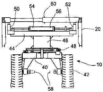
A dolly for a mast wherein the dolly includes a frame having a plurality of
wheels
and a rotating shaft. A pivot shaft allows rotational movement of the support
with respect
to the frame. At least one lifting jack extends or retracts from the rotating
support in order
to lift or lower the mast. At least one mast adjustable width jack moves the
mast between
a wide position and a narrow transport position.

Revendications

Note : Les revendications sont présentées dans la langue officielle dans laquelle elles ont été soumises.


8
WHAT IS CLAIMED IS:
1. A dolly for a transportable mast which comprises:
a frame having a plurality of wheels;
a rotating support to receive said mast;
a pivot shaft allowing rotational movement of said support with respect to
said frame;
at least one lifting jack to extend or retract from said rotating support in
order
to lift or lower said mast; and
at least one mast width adjustment jack to move said mast between a wide
operating position and a narrow transport position.
2. A dolly for a mast as set forth in Claim 1 including a connection on said
frame for steering cables.
3. A dolly for a mast as set forth in Claim 1 including two said mast width
adjustment jacks.
4. A dolly for a mast as set forth in Claim 1 including two said lifting
jacks.
5. A dolly for a mast as set forth in Claim 1 wherein said lifting jack and
said
mast width adjustment jack are each hydraulic.
6. A dolly for a mast as set forth in Claim 1 wherein said lifting jack and
said
mast width adjustment jack are each pneumatic.

9
7. A dolly for a mast as set forth in Claim 1 wherein said lifting jack and
said
mast width adjustment jack are each mechanically actuated.
8. A dolly for a mast as set forth in Claim 1 wherein said mast includes a
back
face, a pair of opposed sides, and an open face wherein said back face
includes a plurality
of trusses, each said truss capable of adjusting between a wide position and a
narrow
transport position.
9. A process to transport a mast, which comprises:
lowering a mast from an upright position on to a rotating support of a dolly
having a frame and a plurality of wheels;
elevating said mast from said rotating table with at least one lifting jack;
and
narrowing a width of said mast with at least one mast width adjustment jack to
move
from a wide position to a retracted transport position.
10. A process to transport a mast as set forth in Claim 9 including the
additional
step of connecting said dolly to a vehicle with steering cables.
11. A process to transport a mast as set forth in Claim 9 wherein a pair of
said
lifting jacks move said mast.
12. A process to transport a mast as set forth in Claim 9 wherein a pair of
said
mast width adjustment jacks narrow said mast.

10
13. A process to transport a mast as set forth in Claim 9 wherein said mast
includes a pair of opposed sides, a back face, and an open face, wherein said
step of
narrowing of said width includes narrowing a width of said back face.
14. A process to transport a mast as set forth in Claim 13 wherein said step
of
narrowing a width of said back face includes adjustable trusses of said back
face.
15. A process to transport a mast which comprises:
increasing a width of a mast supported on a rotating support of a dolly having
a frame and a plurality of wheels with at least one mast jack to move said
mast from a
narrow transport position to a wide position;
lowering said mast toward said rotating support with at least one lifting
jack;
and
raising said mast to an upright position from said rotating support.
16. A process to transport a mast as set forth in Claim 15 wherein a pair of
lifting
jacks move said mast.
17. A process to transport a mast as set forth in Claim 15 wherein a pair of
mast
width adjustment jacks increase said width.
18. A process to transport a mast as set forth in claim 15 wherein said mast
includes a pari of opposed sides, a back face, and an open face, wherein said
step of

11
increasing a width of said mast includes increasing a width of said back face.
19. A process to transport a mast as set forth in Claim 18 wherein said step
of
increasing a width of said mast includes adjustable trusses of said back face.

Description

Note : Les descriptions sont présentées dans la langue officielle dans laquelle elles ont été soumises.


CA 02443508 2003-09-30
1
DOLLY FOR A TRANSPORTABLE ADJUSTABLE WIDTH MAST
BACKGROUND OF THE I~~ENTION
1. >'~eld of the Inven~on.
The present invention is directed to providing a dolly for a transportable
mast and
to a process to disassemble a mast, transport a mast from one location to
another and,
thereafter, erect the mast in the new location. In particular, the present
invention provides
a wheeled dolly that includes a mechanism to open or close an adjustable width
mast.
2. Prio
It is often desirable to move transportable masts from one location to another
from
time to time. There are various reasons for doing so, including moving a
drilling rig to a
new location to drill for oil or gas. In a typical operation to move a mast
from a well site,
14 the mast is lowered from a position vertical to the ground to a horizontal,
reclining position
onto a vehicle or vehicles using the drawworks of the rig including a crown
block with
various lines. A mast pivot provides a rotatable connection between the mast
and the base
or sub-base of the drilling rig apparatus so that the mast swings in a radical
motion. A truck
or other vehicle supports an upper end of the mast and a dolly would support a
lower end of
the mast. The mast will thereby be supported on the vehicle and dolly and may
be moved
to another location.
Transportation of the mast or mast sections over roadways presents additional
problems since the width of the vehicle is limited. As an example, on some
roadways,
vehicles wider than the twelve feet are not permitted. The mast is widest a
the base which
2 o rests on the dolly.
One approach to transporting the mast is to disassemble the various portions
of the

i~
CA 02443508 2003-09-30
a
mast or "rig down" and then reassemble them at the new site. This takes
considerable time
and effort and to the extent it can be avoided, is desirable. From time to
time, portions of
the mast have been known to fold or retract which might be used to decrease
the width of
the mast.
It would be desirable to provide a dolly for a transportable mast that would
avoid the
need for dissembling of the mast during transportation.
It would also be desirable to elevate the mast from a reclining position on
the dolly
in order to disengage it and move it from the base of the drilling rig
apparatus.
It would also be desirable to provide a dolly for a transportable mast having
the
l0 ability to widen or narrow an adjustable width mast while on the dolly and,
thereafter, to
return the mast to an open wide position while on the dolly prior to erection
at another site.

CA 02443508 2003-09-30
3
SUMMAR'~ OF THE INVENTION
'The present invention pertains to a dally which would be attached by a cable
or other
mechanism to a truck or vehicle and used to move a transportable mast from one
location
to another.
A mast is lowered from a vertical, in use position by use of a sling line and
moved
radially to a horizontal position. The present invention is capable of moving
the mast
between a wide operating position and a narrow transport position.
The dolly includes a frame having a plurality of wheels with each wheel
connected
to a half axle.
The dolly also includes a rotating support which is generally parallel with
the frame.
A pivot assembly extends between the frame and the rotating support. A pivot
shaft in the
pivot shaft assembly permits and allows rotational movement of the rotating
support with
respect to the flame. A pair of lifting jacks extend from the rotating
support. The lifting
jacks extend to engage the mast and are capable of lifting the mast. The
lifting jacks are also
capable of retracting and lowering the mast.
The dolly also includes a pair of mast width adjustment jacks utilized to move
the
mast between a wide operating position and a narrow transportation position.

CA 02443508 2003-09-30
4
BRIEF DESCRIPTION OF THE DRAWII~jGS
Figure 1 illustrates a dolly constructed in accordance with the present
invention
adjacent a mast;
Figure 2 ihustrates a mast lowered on its side supported by the dolly of the
present
invention;
Figure 3 illustrates a top view and Figure 4 illustrates a side view of the
dolly
constructed in accordance with the present invention with the mast in narrow
position;
Figure 5 shows a front view of the dolly of the present invention with the
mast in the
wide operating use position while Figure 6 illustrates the dolly shown in
Figure 5 with the
mast in the narrow, transportation position.

CA 02443508 2003-09-30
S
D T L N FT EP E DI N S
The embodiments discussed herein are merely illustrative of specific manners
in
which to make and use the invention and are not to be interpreted as limiting
the scope of
the instant invention.
While the invention has been described with a certain degree of particularity,
it is to
be noted that many modifications may be made in the details of the invention's
construction
and the arrangement of its components without departing from the spirit and
scope of this
disclosure. It is understood that the invention is not limited to the
embodiments set forth
herein for purposes of exemplification.
Referring to the drawings in detail, Figure 1 illustrates a dolly 10
constructed in
s o accordance with the present invention attached to a prime mover such as a
truck vehicle 12
wherein the dolly 10 is connected to the truck 12 by a cable or cables 14.
Various types of
vehicles having a flat bed may be employed. The dolly 10, in combination with
the truck
12, are used to move a transportable mast 20 from one location to another
location.
Figure 1 illustrates the movement of a mast 20 between a vertical and a
horizontal
position. In position for use, the mast 20 will be aligned vertically to the
ground 22 over a
well bore (illustrated by dashed line 24).
In order to transport, the mast 20 is lowered from the vertical position by
use of a
sling line 26 which is reeved over a number of sheaves and fastened at one or
more places
along the mast 20. A gin pole 28 and a drawworks 30 assist in lowering or
raising of the
2 o mast. The drawworks may be mounted on a subbase 38.
Arrow 36 illustrates the radial movement of the mast between the vertical and
horizontal positions.

CA 02443508 2003-09-30
6
It will be understood that the forgoing description of the raising and
lowering of the
mast is known and does not comprise the invention but is provided as
background for an
understanding of the invention.
Figure 2 illustrates a top view of the mast 20 in the horizontal position
resting on the
vehicle 12 and dolly 10.
While the top 32 of the mast 20 is relatively narrow in width, the base
portion 34 of
the mast 20 is often too wide to travel over roadways. The present invention
is capable of
moving the mast between a wide operating position shown in Figure 2 and a
narrow,
transportation position shown in Figures 3 and 4.
Figures 5 and 6 illustrate the dolly 10 with the transportable mast 24
suspended
thereon.
The dolly 10 includes a frame 40 having a plurality of wheels 42. In the
present
case, the dolly 10 includes four wheels, although other arrangements are
possible within the
teachings of the invention. Each wheel is connected to a half axle 58.
The dolly 10 also inchules a rotating support 44 which is generally parallel
with the
frame 40.
A pivot shaft assembly 46 extends between the frame 40 and the rotating
support 44.
A pivot shaft (not visible) in the pivot shaft assembly 4G permits and allows
rotational
movement of the rotating support 44 with respect to the frame. The frame 40
also includes
2 0 a connection 48 to attach a pair of cables 14 attached to the vehicle.
A pair of lifting jacks 50 and 52 extend from the rotating support 44. In
order to
move the mast for transportation on roadways, the mast 20 would be lowered
from the
vertical position onto its side on the dolly 10. The lifting jacks SO and 52
will extend and
lift the mast 20. The base 34 of the mast 20 will be unpinned from the
subbase.

CA 02443508 2003-09-30
7
The dolly 10 also includes a pair of mast jacks 54 and 56 utilized to move the
mast
20 between a wide operating position and a narrow position. In the present
embodiment, a
pair of hydraulic cylinders are utilized although other mechanisms such as
mechanical
actuators might be used.
Figure S illustrates the mast 20 in the wide operating position after it is
lowered onto
the dolly 10. The mast includes a pair of sides and a back face 60 which
telescopes. Other
mechanisms to reduce the width of the back face, such as an articulating back
face, may be
employed.
Figure 6 illustrates the mast 20 in a narrow position so that the base 34 of
the dolly
1 o is reduced to an acceptable width for transportation. When the jacks 54
and 56 are retracted,
the back face 60 of the mast is reduced in width.
Whereas, the present invention has been described in relation to the drawings
attached hereto, it should be understood that other and further modifications,
apart from
those shown or suggested herein, may be made within the spirit and scope of
this invention.

Dessin représentatif
Une figure unique qui représente un dessin illustrant l'invention.
États administratifs

2024-08-01 : Dans le cadre de la transition vers les Brevets de nouvelle génération (BNG), la base de données sur les brevets canadiens (BDBC) contient désormais un Historique d'événement plus détaillé, qui reproduit le Journal des événements de notre nouvelle solution interne.

Veuillez noter que les événements débutant par « Inactive : » se réfèrent à des événements qui ne sont plus utilisés dans notre nouvelle solution interne.

Pour une meilleure compréhension de l'état de la demande ou brevet qui figure sur cette page, la rubrique Mise en garde , et les descriptions de Brevet , Historique d'événement , Taxes périodiques et Historique des paiements devraient être consultées.

Historique d'événement

Description Date
Demande non rétablie avant l'échéance 2012-07-23
Inactive : Morte - Taxe finale impayée 2012-07-23
Réputée abandonnée - omission de répondre à un avis sur les taxes pour le maintien en état 2011-09-30
Réputée abandonnée - les conditions pour l'octroi - jugée non conforme 2011-07-21
Un avis d'acceptation est envoyé 2011-01-21
Lettre envoyée 2011-01-21
Un avis d'acceptation est envoyé 2011-01-21
Inactive : Approuvée aux fins d'acceptation (AFA) 2010-12-17
Modification reçue - modification volontaire 2009-04-29
Lettre envoyée 2008-10-31
Requête d'examen reçue 2008-09-22
Exigences pour une requête d'examen - jugée conforme 2008-09-22
Toutes les exigences pour l'examen - jugée conforme 2008-09-22
Lettre envoyée 2006-01-12
Exigences de rétablissement - réputé conforme pour tous les motifs d'abandon 2005-12-28
Réputée abandonnée - omission de répondre à un avis sur les taxes pour le maintien en état 2005-09-30
Demande publiée (accessible au public) 2004-12-02
Inactive : Page couverture publiée 2004-12-01
Inactive : CIB attribuée 2003-11-28
Inactive : CIB en 1re position 2003-11-28
Inactive : CIB attribuée 2003-11-28
Exigences relatives à une correction du demandeur - jugée conforme 2003-11-04
Lettre envoyée 2003-11-04
Inactive : Certificat de dépôt - Sans RE (Anglais) 2003-11-04
Inactive : Demandeur supprimé 2003-11-04
Demande reçue - nationale ordinaire 2003-10-29

Historique d'abandonnement

Date d'abandonnement Raison Date de rétablissement
2011-09-30
2011-07-21
2005-09-30

Taxes périodiques

Le dernier paiement a été reçu le 2010-09-08

Avis : Si le paiement en totalité n'a pas été reçu au plus tard à la date indiquée, une taxe supplémentaire peut être imposée, soit une des taxes suivantes :

  • taxe de rétablissement ;
  • taxe pour paiement en souffrance ; ou
  • taxe additionnelle pour le renversement d'une péremption réputée.

Les taxes sur les brevets sont ajustées au 1er janvier de chaque année. Les montants ci-dessus sont les montants actuels s'ils sont reçus au plus tard le 31 décembre de l'année en cours.
Veuillez vous référer à la page web des taxes sur les brevets de l'OPIC pour voir tous les montants actuels des taxes.

Historique des taxes

Type de taxes Anniversaire Échéance Date payée
Taxe pour le dépôt - générale 2003-09-30
Enregistrement d'un document 2003-09-30
Rétablissement 2005-12-28
TM (demande, 2e anniv.) - générale 02 2005-09-30 2005-12-28
TM (demande, 3e anniv.) - générale 03 2006-10-02 2006-09-13
TM (demande, 4e anniv.) - générale 04 2007-10-01 2007-05-28
Requête d'examen - générale 2008-09-22
TM (demande, 5e anniv.) - générale 05 2008-09-30 2008-09-23
TM (demande, 6e anniv.) - générale 06 2009-09-30 2009-08-10
TM (demande, 7e anniv.) - générale 07 2010-09-30 2010-09-08
Titulaires au dossier

Les titulaires actuels et antérieures au dossier sont affichés en ordre alphabétique.

Titulaires actuels au dossier
WOOLSLAYER COMPANIES, INC.
Titulaires antérieures au dossier
DEWAYNE VOGT
JOHN BRITTAIN
JOSEPH R. WOOLSLAYER
Les propriétaires antérieurs qui ne figurent pas dans la liste des « Propriétaires au dossier » apparaîtront dans d'autres documents au dossier.
Documents

Pour visionner les fichiers sélectionnés, entrer le code reCAPTCHA :


Pour visualiser une image, cliquer sur un lien dans la colonne description du document. Pour télécharger l'image (les images), cliquer l'une ou plusieurs cases à cocher dans la première colonne et ensuite cliquer sur le bouton "Télécharger sélection en format PDF (archive Zip)" ou le bouton "Télécharger sélection (en un fichier PDF fusionné)".

Liste des documents de brevet publiés et non publiés sur la BDBC .

Si vous avez des difficultés à accéder au contenu, veuillez communiquer avec le Centre de services à la clientèle au 1-866-997-1936, ou envoyer un courriel au Centre de service à la clientèle de l'OPIC.


Description du
Document 
Date
(aaaa-mm-jj) 
Nombre de pages   Taille de l'image (Ko) 
Abrégé 2003-09-29 1 14
Description 2003-09-29 7 240
Revendications 2003-09-29 4 100
Dessins 2003-09-29 4 95
Dessin représentatif 2003-12-18 1 12
Dessin représentatif 2011-01-18 1 11
Courtoisie - Certificat d'enregistrement (document(s) connexe(s)) 2003-11-03 1 106
Certificat de dépôt (anglais) 2003-11-03 1 159
Rappel de taxe de maintien due 2005-05-30 1 110
Courtoisie - Lettre d'abandon (taxe de maintien en état) 2005-11-27 1 174
Avis de retablissement 2006-01-11 1 165
Rappel - requête d'examen 2008-06-01 1 119
Accusé de réception de la requête d'examen 2008-10-30 1 190
Avis du commissaire - Demande jugée acceptable 2011-01-20 1 162
Courtoisie - Lettre d'abandon (AA) 2011-10-12 1 164
Courtoisie - Lettre d'abandon (taxe de maintien en état) 2011-11-24 1 173
Taxes 2005-12-27 2 59
Correspondance 2008-09-21 1 43