Note : Les descriptions sont présentées dans la langue officielle dans laquelle elles ont été soumises.
CA 02443527 2005-11-18
1
PRESSURE WAVE EXPANSION TOOL
FIELD OF THE INVENTION
This invention relates to a downhole tool for use in
deforming a downhole object such as a tubular. In one
embodiment, the present invention relates to a tubing
hanger-forming tool.
BACKGROUND OF THE INVENTION
Tn the oil and. gas exploration and production industry
there is often a requirement to secure a length of bore-
lining tubing to an existing section of tubing. ,One such
arrangement -is known as a hanger, and is used to, for
example, suspend a section of liner to the lower end of an
existing section of casing. Conventional liner hangers
employ mechanical slips and the like, however more recent
proposals have described. the creation of hangers by
expanding the upper end of a liner into engagement with the
surrounding casing, as described in WO00\37772, the
disclosure of which is incorporated herein by reference.
It is amongst the objectives of embodiments of the
present invention to provide an alternative method and
apparatus for creating a liner hanger, and to provide a
tubing expansion tool.
It is amongst further objectives of embodiments of the
CA 02443527 2003-10-08
WO 02/084073 PCT/GB02/01654
invention to provide alternative methods and apparatus for
deforming objects downhole.
SUMMARY OF THE INVENTION
According to a first aspect the present invention
there is provided a downhole tool comprising a body
defining a fluid chamber, a fluid outlet for directing
fluid outwardly of the chamber, and volume reducing means
for producing a rapid reduction in the volume of the
chamber such that fluid in the chamber is displaced rapidly
through the outlet.
The rapid displacement of fluid from the chamber may
be employed to deform a downhole object, which may in
particular comprise a tubular member. The tubular member
may comprise an inner tube for coupling to a larger
diameter outer tube. The outer tube may comprise casing in
a casing lined borehole, and the inner tube may be deformed
into engagement with the casing to form a tubing hanger.
The present invention is therefore particularly
advantageous in that it allows a tubing hanger to be
created by providing a length of tube, locating the tube in
the casing and directing the fluid displaced from the tool
chamber towards an inner surface of the tubing. The forces
created by the rapid displacement of the fluid deforms the
inner tubing into engagement with the inner surface of the
casing, and the deformed tube may then act as a tubing
CA 02443527 2003-10-08
WO 02/084073 PCT/GB02/01654
3
. hanger.
Alternatively, the invention may be utilised to create
a profile in tubing, or to secure a ring or short sleeve
within existing tubing. In other embodiments, the
invention may even be utilised to puncture. or punch a hole
in existing tubing.
Preferably, the volume reducing means includes a
member moveably mounted in the body and defining a wall of
the.fluid chamber. The volume reducing means may further
include a second member mounted in the body, which may be
movable to impact on and move the first member. The second
member may be moveable between a first position, spaced
from the first member, and a second position, in contact
with the first member.
l5 ~It will therefore be understood that, in this
embodiment, the rapid displacement of fluid from the
chamber is achieved by rapidly moving the second member to
impact the first member, which is then rapidly moved to
reduce the volume of the fluid chamber and displace the
fluid out of the chamber through the outlet.
Conveniently, the second member is initially
restrained in the first position. The second member may be
restrained by a shear pin or other release mechanism which
is adapted to release the second member when, for example,
a predetermined force is exerted on the second member.
Alternatively, the release mechanism may be retractable or
CA 02443527 2003-10-08
WO 02/084073 PCT/GB02/01654
4
otherwise moveable to release the second member; for
example, the mechanism may comprise a latch or key which is
retracted in response to a signal sent from surface, or in
response to the tool engaging a no-go or other bore
restriction or profile.
The first member may similarly be releasably retained
in an initial position.
Preferably, the second member is moveable in response
to a fluid pressure force, and may selectively communicate
with a fluid pressure source. The fluid pressure source
may comprise fluid in the borehole. In a deep borehole,
the hydrostatic pressure experienced by the tool may be in
the order of several hundred atmospheres, such that by
selectively exposing the second member to bore pressure, a
large pressure force may be generated. This pressure force
is preferably communicated to the second member via an
energy storage medium, such as a spring or a compressible
fluid, typically an inert gas such as Nitrogen.
Alternatively, the second member may be coupled to a
fluid pressure source which has been charged with high
pressure compressible fluid, such an Nitrogen or another
inert gas. The charging may take place on surface,
utilising, for example, bottled Nitrogen at 200 - 300 bar.
In another embodiment, the fluid pressure source may
comprise a propellant; a firing pin may be released to
initiate a reaction resulting in the production of a
CA 02443527 2003-10-08
WO 02/084073 PCT/GB02/01654
significant volume of high pressure gas.
A burst disk, valve or other arrangement may be
provided between the fluid pressure source and the second
member. Alternatively, or in addition, the second member
5 may be initially retained in the first position.
Movement of the second member may therefore be
achieved by providing pressurised fluid in the tool, 'to
exert a fluid pressure force on the second member. In this
manner, the tool may effectively self-contained, and may be
mounted on a reelable support' member such as slickline or
wireline.
Preferably, the first and second members comprise
respective first and second pistons. A face of the first
piston may define the wall of the deforming fluid chamber.
Conveniently, the first and second pistons are annular
pistons, which may be mounted in an annular chamber defined
by the body and through which the second piston is movable.
In other embodiments cylindrical pistons may be more
appropriate or convenient. Thus, one face of the first
piston may define a first end wall of the piston-
accommodating chamber, and the other face defining a wall
of the deforming fluid chamber.
Conveniently, a second end of the piston chamber is
coupled to a fluid pressure source, for selectively
exposing one face of the second piston to an elevated
pressure with respect to the other face of the piston.
CA 02443527 2003-10-08
WO 02/084073 PCT/GB02/01654
6
Preferably, the first end portion of the piston
chamber is under vacuum. Alternatively, the body may
include a fluid communication port for opening the first
end of the chamber to the exterior of the tool. In a
further alternative, the first end portion of the piston
chamber initially contains compressible fluid, typically
Nitrogen or another inert gas, at surface atmospheric
pressure.
In other -embodiments the tool may be activated by
means other than or in addition to applied fluid pressure,
including an explosive charge, a precompressed spring, a
jar or a falling mass.
Preferably, the body is tubular. The outlet may
comprise an annular opening extending around the body of
the tool, and the outlet may be adjustable in dimension.
The body may include an adjustable member and the outlet
may be defined between the adjustable member and a part of
the body. The adjustable member may include a threaded nut
or other member which may be rotated to vary the spacing
between the adjustable member and the part of the body.
This may be advantageous in optimising fluid flow through
the outlet for particular applications.
Alternatively, the tool may include a plurality of
outlets spaced around a perimeter of the body, to provide
a predetermined distribution of the fluid during
displacement from the body, and thus achieve a
CA 02443527 2003-10-08
WO 02/084073 PCT/GB02/01654
7
predetermined pattern of deformation of the object. The
outlets may be evenly or unevenly spaced around a
circumference of the body, and may be defined by
castellations formed in the body.
In other embodiments, only a single directed outlet
may be provided, to create a relatively small area of
deformation.
Preferably, the outlet or outlets are in the form of
nozzles.
According to a second aspect of the present invention,
there is provided a downhole tool assembly comprising:
an object for location in a well; and
a downhole tool comprising a body defining a fluid
chamber, a fluid outlet for directing fluid outwardly of
the chamber, and volume reducing means for producing a
rapid reduction in the volume of the chamber such that
fluid is displaced rapidly through the outlet to impinge
upon and deform the object.
Conveniently, the object comprises a tubular member.
In particular, the object may comprise an inner, first tube
for location in an outer, second tube, such that the tool
may be utilised to deform the inner tube into engagement
with the outer tube. The inner tube may comprise a
deformable tubing anchor for securing a length of tubing in
the outer tube.
Thus, it will be understood that the invention may
CA 02443527 2003-10-08
WO 02/084073 PCT/GB02/01654
8
advantageously be used as a tubing anchor activating tool;
the tool deforms an inner tube by displacing fluid from the
chamber and directing the fluid towards the inner tube,
which deforms the tube into engagement with an outer tube,
securing the inner tube in the outer tube, to serve as a
tubing hanger.
The inner tube forming the tubing anchor may comprise
part of the length of tubing to be hung from the outer
tube. Alternatively, the inner tube may be separate from
the length of tubing and the length of tubing may be
coupled to the inner tube. The inner tube may be for
location in a length of casing forming the outer tube, such
as borehole-lining casing.
In alternative embodiments the object may comprise
existing downhole tubing, the tool being used to create a
profile in the tubing or to puncture or perforate the
tubing.
In still further embodiments the object may comprise
a ring or a short sleeve, which may be run into the bore
with the tool.
According to a third aspect of the present invention
there is provided a method of deforming an object downhole,
the method comprising:
providing a tool having a body defining a chamber and
containing a fluid;
directing a fluid outlet from the chamber towards an
CA 02443527 2003-10-08
WO 02/084073 PCT/GB02/01654
9
object to be deformed; and
rapidly reducing the volume of the chamber such that
fluid is ejected from the chamber through the outlet and
towards the object, and deforms the object.
Although not wishing to be bound by theory, it is
believed that the sudden ejection of fluid from the chamber
through the outlet at high pressure creates a travelling
pressure wave which impacts the object to be deformed.
Preferably, the method further comprises the steps of:
providing an inner, first tube to be deformed;
locating the inner tube in an outer, second tube of
larger internal diameter than the external diameter of the
undeformed inner tube;
locating the tool in the inner tube: and
deforming the inner tube into engagement with the
outer tube.
The tube may be a ring, sleeve, or part of a hanger or
packer.
The step of rapidly reducing the volume of the chamber
may further comprise providing a member moveably mounted in
the body and defining a wall of the chamber, and rapidly
moving the member. Preferably, a second member is provided
moveably mounted in the body, and the second member is
impacted against the first member. Furthermore, the first
and second members may be provided in the form of
°respective first and second pistons mounted in a second
CA 02443527 2003-10-08
WO 02/084073 PCT/GB02/01654
chamber in the body.
The volume of the chamber may be rapidly reduced by
generating a pressure differential across the second member
to move the second member and to impact the second member
5 against the first member. Conveniently, the pressure
differential is generated by exposing one face of the
second piston to an elevated pressure with respect to the
other face of the second piston. The second piston may be
restrained against movement until the pressure differential
10 across the second piston reaches a pre-determined level, or
on receipt of an appropriate control signal.
The fluid may be directed through a plurality of
outlets to distribute the ejected fluid around a perimeter
of the object. Alternatively, the fluid may be directed
through a single, annular outlet, or through a single
unidirectional outlet.
According to a further aspect the present invention
there is provided a downhole tool comprising a body
defining a fluid chamber, a movable member in communication
with the chamber, and volume reducing means for producing
a rapid reduction in the volume of the chamber such that
fluid in the chamber acts on the member to move the member
rapidly outwardly of the tool body.
Preferably, the member is mounted to be normally
retracted in the tool body,~for example the member may be
spring-mounted to the body.
CA 02443527 2005-11-18
11
The member may comprise a punch or a bolt.
According to a still further aspect of the present
invention there is.provided a method of striking an object
downhole, the method comprising:
providing a tool having a body defining a chamber and
containing a fluid, and a member movably mounted in the
body and in communication with the chamber;
either rapidly reducing the volume of the chamber or
increasing the pressure of the fluid such that the fluid in
the chamber acts on the member and moves the member rapidly
outwardly of the tool body; and
impacting the moving member on a downhole object_
Preferably, the moving member deforms-the object, and
may puncture or perforate the member.
In another aspect, the invention provides a downhole
tool for plastically deforming an object, the tool
comprising a body defining a fluid chamber, a fluid outlet
for directing fluid outwardly of the chamber towards a
downhole object, and volume reducing means for producing a
rapid reduction in the volume of the chamber to displace
fluid from the chamber such that the displaced fluid is
ejected rapidly through the outlet towards the object to be
plastically deformed.
In another aspect, the invention provides a downhole
tool assembly comprising a downhole object for location in
a well, and a downhole tool comprising a body defining a
fluid chamber, a fluid outlet for directing fluid outwardly
of the chamber, and volume reducing means for producing a
rapid reduction in the volume of the chamber to displace
fluid from the chamber such that the displaced fluid is
CA 02443527 2005-11-18
lla
ejected rapidly through the outlet to impinge upon and
plastically deform the downhole object.
In another aspect, the invention provides a method of
deforming an object, the method comprising providing a tool
having a body defining a chamber and containing a fluid,
directing a fluid outlet from the chamber towards an object
to be deformed, locating the tool downhole, within an
object to be deformed, and rapidly reducing the volume of
the chamber to displace fluid from the chamber such that
the displaced fluid is ejected from the chamber through the
outlet and towards the object and plastically deforms the
object.
In another aspect, the invention provides a downhole
tool for plastically deforming an object, the tool
comprising a body defining a fluid chamber, a movable
member in communication with the chamber, and volume
reducing means for producing a rapid reduction in the
volume of the chamber such that fluid in the chamber acts
on the member to move the member rapidly outwardly of the
tool body towards the object to be plastically deformed.
These embodiments of the invention may utilise volume
reducing means similar to those described above.
BRIEF DESCRIPTION OF THE DRAWINGS
Embodiments of the present invention will now be
described, by way of example only, with reference to the
accompanying drawings, in which:
Figure 1 is a view of a downhole tool in accordance
with a preferred embodiment of the present invention, in
the form of a hanger activating tool;
Figure 2 is a longitudinal cross-sectional view of the
tool of Figure 1, taken along line A-A of Figure 1;
CA 02443527 2003-10-08
WO 02/084073 PCT/GB02/01654
12
Figure 3 is a view similar to Figure 2, showing the
tool in use, before activation; and
Figure 4 is a view of the tool of Figure 3, during
activation.
DETAILED DESCRIPTION OF THE DRAWINGS
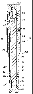
Referring first to Figures 1 and 2, there is shown a
downhole tool indicated generally by reference numeral 10.
The tool 20 is shown in more detail in the longitudinal
cross-sectional view of Figure 2, which is taken on line A-
A of Figure 1. The tool 10 comprises a generally tubular
body 12 which defines a fluid chamber 14, a fluid outlet 16
for directing fluid outwardly of the chamber 14 and volume
reducing means indicated generally by reference numeral 18.
As will be described in more detail below, the volume
reducing means 18 may be utilised to produce a rapid
reduction in the volume of the fluid chamber 14, such that
fluid is displaced rapidly through the outlet 16.
In the embodiment shown, the downhole tool 10
comprises a hanger activating tool for use in downhole
environments to activate a tubing hanger. As will be
understood by persons slcilled in the art, a tubing hanger
is used in situations where it is desired to suspend a
length of tubing from an existing larger diameter tube.
Typically, a hanger may be utilised to suspend a length of
liner in a casing-lined borehole. The tool 10 is typically
CA 02443527 2003-10-08
WO 02/084073 PCT/GB02/01654
13
run into a borehole on coiled tubing, wireline, slickline
or the like (not shown) to allow the tool to be easily
tripped in and out of the borehole.
The body 12 is generally tubular and defines a second
internal annular chamber 20. The volume reducing means
includes a first member in the form of first annular piston
22 .and a second member in the form of a second annular
piston 24, each of which is moveably mounted in the body 12
around a central mandrel 26. The first piston 22 has a
lower piston face 28 which defines an upper wall of the
.chamber 14. The second piston 24 is initially spaced from
the first piston 22 and restrained from movement within the
chamber 20 by a releasable pin 30.
The fluid chamber outlet 16 extends around the
circumference of the body 12, and is in the form of an
annular nozzle defined between a lower outer casing 13 of
the body 12 an adjustable member 17 which includes a collar
23 and a threaded retaining nut 25. The collar 23 defines
a lower wall of the fluid chamber 14 and is mounted on the
nut 25, which in turn is mounted on the threaded end 19 of
the mandrel 26. The nut 25 is rotatable on the shaft to
vary the spacing between the lower casing 13 and the sleeve
23, and thus the dimension of the outlet 16.
The tool 10 is adapted to be coupled to a high
pressure fluid supply through an input port 32 which
communicates with an upper end 34 of the annular chamber 20
CA 02443527 2003-10-08
WO 02/084073 PCT/GB02/01654
14
through a central passage 36 and flow port 38 in the
mandrel 26. In use, the chamber upper end 34 is charged
with high pressure (200 - 300 psi) inert gas, typically
Nitrogen. The other, lower end 40 of the annular chamber
20 is under vacuum, having been evacuated through a
closeable port 21 before running the tool.
Thus, an upper piston face 42 of the second piston 24
is exposed to an elevated pressure with respect to the
lower piston face 44. This pressure differential create s
a significant axial force on the piston 24 which, as will
be described, may be utilised to move the second piston 24
downwardly, to impact the first piston 22.
Turning now also to Figure 3, the to~1 10 is shown
located in an inner, first tube 46 which is to be coupled
to an outer, second tube 48. The outer tube 48 is
typically casing for lining the borehole of a well, whilst
the inner tube 46 is a deformable tubing hanger, which is
to be deformed into engagement with the outer tube 48. The
hanger 46 may form part of a string of liner to be hung
20, from the casing 48, or a string of liner may be coupled to
the hanger 46.
Figure 4 shows the activated tool 10, in the course of
forming the hanger 46. As noted above, the high pressure
gas in the upper end of the annular chamber 34 creates a
differential pressure across the second piston 24. This
generates a fluid pressure force upon the second piston 24,
CA 02443527 2003-10-08
WO 02/084073 PCT/GB02/01654
and on release of the pin 30 the elevated pressure of fluid
in the upper chamber end 34, acting on the upper piston
face 42, accelerates the unrestrained second piston 24
downwardly through the chamber 20, in the direction of the
5 arrow B, to impact the first piston 22. The transfer of
momentum causes the first piston 22 to move rapidly
downwardly, displacing fluid from the chamber 14 and
through the outlet 16.
As shown in Figure 4, the incompressible well bore
10 fluid is displaced through the outlet 16 in the direction
C, creating a high pressure wave travelling radially
outward to impinge upon an inner surface 50 of the tubing
hanger 46, plastically deforming the inner tube into
engagement with the inner surface 52 of the casing 48. The
15 outer surface 54 of the hanger 46 carries carbide chips on
the outer surface in the area to be deformed, to provide
secure engagement with the casing inner surface 52. The
hanger 46 is thus set in the casing 48. The tool 10 is
then retrieved to surface and the desired well operations
may proceed through the liner tubing 46 which is now
secured in the casing 48.
It will be understood that references herein to
"upper" and "lower" ends of the annular chamber are fox
ease of reference in the accompanying drawings. In use, in
particular in deviated wells, the orientation of the tool
may be such that the ends of the annular chamber are not
CA 02443527 2003-10-08
WO 02/084073 PCT/GB02/01654
16
located in upper and lower positions as shown in the
drawings.
Various modifications may be made to the foregoing
embodiments within the scope of the present invention. For
example, the lower end 40 of the annular chamber 20 may
initially contain low pressure,fluid which is compressed or
exhausted from the body 12 through the port 21 as the
second piston 24 moves through the chamber. Alternatively,
the lower end of the annular chamber 40 may contain a
fluid, in particular a gas, at surface atmospheric pressure
and may be sealed at the surface before the tool 10 is run
into the borehole. In a further alternative, the lower end
portion of the annular chamber 40 may be open to the
exterior of the tool, such that fluid in the chamber 20
experiences annulus pressure.
The fluid pressure source for supplying pressurised
fluid to the upper end 34 of the annular chamber 20 may
comprise the head of fluid in the borehole; in a deep bore,
the column of fluid in the bore may produce a significant
hydrostatic pressure, which may be further increased by the
action of surface or downhole pumps. Such fluid pressure
may be communicated to a chamber above the second piston
containing a compressible gas spring. via a floating piston.
The fluid chamber 16 as described above is open to the
exterior of the tool and fills with well fluid as the tool
is lowered into the bore. However, in other embodiments
CA 02443527 2003-10-08
WO 02/084073 PCT/GB02/01654
17
the chamber 16 could be initially filled with gel or other
fluid, which fluid could be contained in the chamber 16 by
a frangible barrier.
In other embodiments the tool may be utilised to
deform existing tubing to, for example, create a tool-
locating profile. Alternatively, the tool may be used to
deform and locate a ring or sleeve in a bore. The ring may
serve to locate tools or devices, and the sleeve may serve
a variety of purposes and may, for example, form the upper
part of a packer.
Furthermore, in certain embodiments of the invention
the deformation may not be achieved by a travelling
pressure wave, but by a member, such as a bolt, which is
acted upon by the fluid in the chamber to move rapidly from
~ the tool to, for example, punch a hole in existing casing.
Finally, the above described embodiments of the
invention are described in relation to downhole
applications, however the various aspects of the present
invention may also be utilised in other applications.