Note : Les descriptions sont présentées dans la langue officielle dans laquelle elles ont été soumises.
CA 02444034 2003-10-08
FOOD SERVING BAR
Background of the Invention
The present invention relates generally to the food service industry, and more
particularly to food serving bars which are temperature controlled to maintain
food at a
suitable temperature as it is being served.
This invention is generally in the same field as U.S. patents 4,407,143,
4,782,665,
4,856,579 and 4,870,835, owned by Duke Manufacturing Company, disclosing
refrigerated food serving equipment known as frost top units which give the
appearance
that the food products being served are resting in ice. U.S. Patent Nos.
5,355,687 and
5,927,092 disclose other types of refrigerated units for holding food pans.
Summary of the Invention
Among the several objects of this invention will be noted the provision of a
food
serving bar which is equipped for holding a number of relatively small (e.g.,
6.9 in. wide
by 12.8 in. long) food pans in parallel rows; the provision of such a serving
bar which
efficiently cools and/or heats the food in all such pans substantially
uniformly; the
provision of such a serving bar which is economical to manufacture and
attractive in
appearance; and the provision of such a serving bar which can easily retrofit
a
conventional frost top unit.
In general, a temperature controlled food serving bar of this invention
comprises a
cabinet having a bottom, opposite sides and opposite ends defining an interior
space. A
top wall overlies the base and has an opening therein above the interior
space. A plurality
of elongate, generally parallel, spaced apart dividers of thermally conductive
material
extend lengthwise of the cabinet in or below the opening. The dividers have
side walls
extending down into the interior space of the cabinet dividing the interior
space into a
plurality of elongate generally parallel cavities extending lengthwise of the
cabinet. A
temperature control system having a plurality of heat transfer lines extending
along the
side walls of the dividers at locations outside the cavities controls the
temperature of the
side walls. Upwardly facing surfaces on the dividers support food-holding pans
in
1
CA 02444034 2006-06-05
64725-940
positions in which the pans extend down into the cavities
adjacent the side walls of the dividers for being heated or
cooled thereby. Thermal barriers are provided below the
upwardly facing surfaces to inhibit the transfer of heat
between the dividers and the upward facing surfaces.
The present invention is also direct to a
temperature-controlled food serving bar having at least two,
generally parallel, spaced apart channels of thermally
conductive material. The channels extend lengthwise of the
cabinet in or below the opening. Each channel has a bottom
wall and opposing side walls defining an elongate cavity
extending lengthwise of the cabinet. The temperature
control system comprises a plurality of heat transfer lines
extending along the side walls of the channels at locations
outside the cavities. Upwardly facing surfaces on the
channels support food-holding pans in positions in which the
pans extend down into the cavities adjacent the side walls
of the channels for being heated or cooled thereby.
According to another aspect of the present
invention, there is provided a temperature-controlled food
serving bar comprising a cabinet having a bottom, opposite
sides and opposite ends defining an interior space, a top
wall and an opening in the top wall above said interior
space, at least two generally parallel, spaced apart
channels of thermally conductive material extending
lengthwise of the cabinet in or below said opening, each
channel having a bottom wall and opposing side walls
defining an elongate cavity extending lengthwise of the
cabinet, a temperature control system comprising a plurality
of heat transfer lines extending along the side walls of the
channels at locations outside said cavities, and upwardly
facing surfaces on the channels for supporting food-holding
2
CA 02444034 2008-02-11
64725-940
pans in positions in which the pans extend down into said
cavities adjacent the side walls of the channels for being
heated or cooled thereby.
According to still another aspect of the present
invention, there is provided a temperature-controlled food
serving bar comprising a cabinet having a bottom, opposite
sides and opposite ends defining an interior cabinet space,
a top wall, and an elongate opening in the top wall above
said interior cabinet space, at least three channels of
thermally conductive material extending the length of the
elongate cabinet opening and dividing the interior cabinet
space into a plurality of elongate, pan-receiving cavities
each of which opens upwardly along the entire length of the
cavity to allow placement of multiple food-holding pans in
the cavity at any desired location along the cavity, each of
said channels having generally parallel channel side walls
connected by a bottom wall, a plurality of about 6.9 in.-
wide food-holding pans received in one or more of the pan-
receiving cavities, and a temperature control system for
controlling the temperature of the channel side walls to
control the temperature of said food-holding pans in said
cavities.
According to yet another aspect of the present
invention, there is provided a temperature-controlled food
serving bar comprising a cabinet having opposite sides and
opposite ends defining an elongate interior cabinet space
extending endwise of the cabinet, a plurality of channels of
thermally conductive material extending lengthwise of the
elongate interior cabinet space and dividing the interior
cabinet space into a plurality of elongate, upward-opening
pan-receiving cavities each of which extends endwise of the
cabinet to allow placement of at least one food-holding pan
2a
CA 02444034 2008-02-11
64725-940
in the cavity at any desired location along the cavity, each
channel comprising a pair of side walls and a bottom wall,
at least one of the bottom and side walls having a wall
thickness between about 0.1 inch and about 0.2 inch, food-
holding pans received in said pan-receiving cavities, each
pan having a bottom wall and side walls, at least one of the
side walis of the at least one food-holding pan being spaced
from a side wall of a respective channel between about 0.03
inch and about 0.15 inch, and a temperature control system
for controlling the temperature of the channels.
According to a further aspect of the present
invention, there is provided a temperature-controlled food
serving bar comprising a cabinet having opposite sides and
opposite ends defining an elongate interior cabinet space
extending endwise of the cabinet, at least three channels of
thermally conductive material extending lengthwise of the
elongate interior cabinet space and dividing the interior
cabinet space into a plurality of elongate, upward-opening
pan-receiving cavities each of which extends endwise of the
cabinet to allow placement of multiple food-holding pans in
the cavity at any desired location along the cavity, and a
temperature control system for controlling the temperature
of said at least three channels to heat or cool said food-
holding pans in said cavities.
Other objects and features will be in part
apparent and in part pointed out hereinafter.
Brief Description of the Drawings
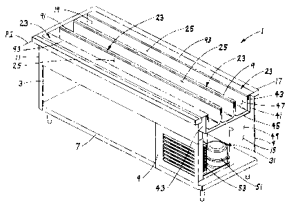
Fig. 1 is a perspective of a first embodiment of a
food serving bar of the present invention.
2b
CA 02444034 2006-06-05
64725-940
Fig. 2 is a sectional view showing a plurality of
dividers and cavities in the food serving bar, and a food
pan in one of the cavities.
Fig. 3 is an enlarged portion of Fig. 2 showing an
inner substantially vertical interior space of the food
serving bar.
Fig. 4 is an enlarged portion of Fig. 2 showing an
outer substantially vertical interior space of the food
serving bar.
Fig. 5 is a detail cut-away of a portion of the
food serving bar of Fig. 1.
Fig. 6 is a perspective of a second embodiment of
a food serving bar of the present invention.
Fig. 7 is a sectional view showing a plurality of
dividers and cavities in the food serving bar of Fig. 6, and
a food pan in one of the cavities.
2c
CA 02444034 2003-10-08
Fig. 8 is a detail cut-away of a portion of the food serving bar of Fig. 6.
Fig. 9 is a perspective of a third embodiment of a food serving bar of the
present
invention,
Fig. 10 is a sectional view showing a plurality of dividers and cavities in
the food
serving bar of Fig. 9, and a food pan in one of the cavities.
Fig. 11 is a perspective of a fourth embodiment of a food serving bar of the
present
invention.
Fig. 12 is a sectional view showing a plurality of dividers and cavities in
the food
serving bar of Fig. 11, and a food pan in one of the cavities.
Corresponding parts are designated by corresponding reference numbers
throughout the drawings.
Description of Preferred Embodiments
Referring to the drawings, and first and more particularly to Fig. 1, a food
serving
bar of the present invention is designated in its entirety by the reference
numeral 1. The
bar I comprises a base 3 in the form of a cabinet having a bottom wal17, side
walls 9 and
end walls 11 defining an interior space 15. A top wall 17 overlies the
interior space 15 and
has an opening 19 therein, preferably but not necessarily elongate, above the
interior space.
In the illustrated embodiment of Fig. 1, one of the end walls 1 I and a
portion of one of the
side walls 9 have been removed to more clearly illustrate the interior space
15. A plurality
of elongate generally parallel dividers, each generally designated 23, of
thermally
conductive material (e.g., extruded aluminum) extend lengthwise of the cabinet
3 in the
interior space 15 below the opening 19 in the top wall 17. The dividers 23
define a
plurality of elongate generally parallel pan-receiving cavities 25 for
receiving generally
parallel rows of food-holding pans 27 extending lengthwise of the base 3 in
the interior
space 15, one such pan being shown in Fig. 2. The bar I also includes a
temperature
control system 31 comprising, in the preferred embodiment, a plurality of heat
transfer
lines 33 for heating or cooling the dividers 23 and the pans 27 received in
the cavities 25,
as will be described in more detail hereinafter. In the embodiments described
below, the
temperature control system 31 is a refrigeration system for cooling the
dividers 23 and
3
CA 02444034 2003-10-08
pans 27, but it will be understood that the temperature control system could
also be
operable to heat the dividers and pans.
Referring to Figs. 1-5, the food serving bar 1 includes a pan-shaped liner 41
fabricated of sheet metal, for example, suitably secured (e.g., welded) to the
top wall 17 of
the cabinet 3. The liner 41 has side walls 43 extending down from the top wall
17 and a
bottom wa1145 spaced below the opening 19 in the top wall 17 and below the
dividers 23.
The liner 41 divides the interior space 15 of the cabinet 3 into an upper
section 47 inside
the liner and a lower section 49 below the liner. A compressor 51 and
evaporator 53 of the
aforementioned refrigeration system 31 are located in the lower section 49 for
cooling the
lower part of the cabinet 3 in conventional fashion. The refrigeration lines
33 for cooling
the dividers 23 are connected to the compressor 51 by quick-connect/disconnect
mechanisms, soldering or other suitable means (not shown).
In the embodiment shown in Figs. 1-5, each divider 23 comprises a channe161
having a bottom wa1163 and side walls 65 extending up from the bottom wall to
define
one of the pan-receiving cavities 25. Three such channels 61 are shown, but
this number
can vary (e.g., two, four or more than four). The channels 61 can be
fabricated of stamped
sheet metal, or extruded or cast of thermally conductive material (e.g.,
aluminum or
stainless steel). Further, each channe161 can be an assembly of such parts, or
a single
extrusion or casting. The channels 61 can be formed separate from one another,
or as a
unitary structure. In a preferred embodiment, each channel 61 is of extruded
aluminum
having a wall thickness in the range of from about 0.1 in. to about 0.2 in.
The parallel
channels 61 are spaced apart a suitable distance (e.g., 1.1 in.) to form inner
substantially
vertical interior spaces 67 between adjacent side walls 65 of adjacent
channels. Further,
the sides 43 of the liner 41 are spaced from the outer side walls 65 of the
two outside
channels 61 to form outer substantially vertical interior spaces 71. The liner
41 is spaced
below the bottom walls 63 of the channels 61 to define a generally horizontal
interior
space indicated at 73.
The heat transfer lines 33 are located in the inner and outer vertical spaces,
67 and
71 respectively, alongside the side walls 65 of the channels 61, preferably
adjacent the
upper ends of the side walls for cooling (or heating) the upper side portions
of the pans 27
4
CA 02444034 2003-10-08
disposed in the channels. The heat transfer lines 33 may comprise lengths of
copper
tubing running the lengths of the channels 61 for carrying a suitable heat
transfer medium
(e.g., coolant). To insure good heat transfer between the lines 33 and the
channel walls 65,
the lines are preferably secured so that they are in direct contact with the
walls, as by
brackets 75 attached (e.g., welded) to the walls 65 at suitable intervals
along the walls.
The required size and configuration of lines 33 will depend on the size of the
pans 27, the
desired temperature at which the food in the pans is to be maintained, the
amount and type
of food being maintained, and other factors apparent to those skilled in this
field. As
shown in Fig. 2, two runs of lines 33 (upper and lower) are provided along the
upper
portion of each side wall 65 of each channel 61, the runs being stacked
relatively closely
one above the other. In the illustrated embodiment of Figs. 1-5, the heat
transfer lines 33
are substantially parallel with the channels 61 extending the length of the
food bar 1 thus
eliminating the need for heat transfer lines that extend transversely across
the channels 61
at locations between adjacent pans 27 in the cavities 25. By way of example,
but not
limitation, the lines 33 may be 3/8 in. OD copper tubing, with the centers of
the runs being
spaced about 0.6 in. apart, and the overall vertical distance D (Fig. 3) being
about 1.0 in. It
will be understood that more or less than two lines 33 can be used to cool or
heat each wall
65 (which is thus referred to as a temperature-controlled wall). The lines 33
may be
formed as a single serpentine coil, as shown in Figs. 1-5, or as a number
(e.g., three) of
separate coils connected together. In any event, the interior spaces 67 and 71
between the
liner 41 and the channels 61 are preferably substantially filled with thermal
insulation. As
shown in Fig. 2, this insulation comprises, in one embodiment, strips of
thermal insulation
81 surrounding the heat transfer lines 33 on all sides except the sides
immediately adjacent
the heat transfer walls 65 of the channels 61. A foam-type insulation 83 fills
the vertical
spaces 67 and 71 not occupied by the strips 81 as well as the horizontal
interior space 73
between the channels 61 and the liner 41. The strips of insulation 81 may be
polystyrene,
for example, and the foam-type insulation 83 may be polyurethane. Other types
of
insulation may be used to maximize the efficiency of heat transfer between the
lines 33
and the channels 61.
5
CA 02444034 2003-10-08
In the embodiment of Figs. 1-5, the side walls 65 of adjacent channels 61 are
bridged by caps 91 of a wear resistant material (e.g., stainless steel)
overlying the inner
substantially vertical interior spaces 67 between the channels. The caps 91
may be secured
in place by tack welding, adhesive or other suitable means. Preferably, the
caps 91 are
removable so that they can be replaced if damaged or as they become worn.
Extensions 93
of the top wall 17 of the cabinet 3 overlie the outer substantially vertical
interior spaces 71
between the liner 41 and the outer two channels 61 along opposite sides of the
opening 19.
These caps 91 and extensions 93 have upward facing surfaces 95 which lie
substantially in
the plane Pl of the top wall 17 of the cabinet 3 and support the peripheral
lips 97 of the
food-holding pans 27 to support the pans in respective cavities 25, one such
pan being
shown in Fig. 2. Thermal barriers 99 are provided below the caps 91 and the
top wall
extensions 93 to prevent frosting (or overheating) of these areas. The thermal
barriers 99
may be of a suitable heat insulating material, such as polycarbonate. The caps
91, thermal
barriers 99 and top wall extensions 93 have vertical flanges, 121, 123 and 125
respectively, which mate against horizontal shoulders 127 formed in the upper
ends of the
side walls 65 of the channels 61 to form relatively smooth flat continuous
junctions
between the channel side walls and the caps and between the channel side walls
and the
top wall extensions to facilitate maintenance and to provide a clean
attractive appearance
(see Figs. 3 and 4). hl one embodiment, the top heat transfer line 33 along
each channel
side wa1165 is positioned closely adjacent (preferably touching) a respective
horizontal
shoulder 127.
Referring to Fig. 2, each channel 61 preferably has a width between the side
walls
65 not substantially greater than the width of a pan 27 received in the cavity
25 defined by
the channel, so that the sides 135 of the pan are spaced relatively close
(e.g., in range of
from about 0.03 to 0.15 in.) to the temperature-controlled side walls of the
channel. This
will insure good heat transfer between the channel 61 and the pan 27.
Typically, the sides
135 of the pan 27 are tapered, with the bottom 137 of the pan being somewhat
narrower
than the top 139 of the pan. Thus, when the pan 27 is positioned in a
channe161, as shown
in Fig. 2, the top 139 of the pan will be closest to the substantially
vertical side walls 65 of
6
CA 02444034 2003-10-08
the channel where the heat transfer lines 33 are located for efficient cooling
(or heating) of
the pans. Preferably, the depth of the channels 61 should be such that there
is about 0.5 in.
between the bottom wa1163 of the channel and the bottoms 137 of the pans 27. A
relatively small spacing is advantageous to maintain in that a smaller cavity
between the
channels 61 and the pans 27 can be cooled (or heated) more efficiently. The
length of the
channels 61 will vary, depending on the dimensions of the opening 19 in the
top wall 17 of
the cabinet 3, but typically will be in the range of from about 54 in. to
about 82 in.
While the heat transfer lines 33 described above are preferably standard
copper
tubing, it is contemplated that other types of thermal fluid lines may be
used. For
example, aluminum microchannel extrusions of the type commercially available
from
Thermalex, Inc. of Montgomery, Alabama may also be suitable. Further, the
channel walls
65 can be heated or cooled by other mechanisms, such as by a forced air system
in which
temperature controlled air is circulated between the channels to heat or cool
them, or an air
impingement system of the type developed by Enersyst Development Center in
which jets
of high pressure, high velocity, temperature controlled air are directed onto
the walls of the
channels. The use of a bath system in which the channels 61 are immersed in a
thermal
fluid is also contemplated.
To prevent over-cooling of the pans and their contents in a situation where
the food
serving bar is refrigerated, heating elements 145 may be provided along the
bottom wa1163
of each channe161, as shown in Fig. 2. The heating elements 145 may be
electric
resistance heating elements, for example. Temperature sensors (not shown) may
be used
to sense the temperatures of the pans 27 and/or channels 61, and to signal the
operation of
the appropriate heating elements 145 if and when needed.
Figs. 6-8 illustrate a second embodiment of a food server of the present
invention,
generally designated 201. This embodiment is substantially identical to the
first
embodiment, except that the upward facing surfaces 202 of the pan-supporting
caps 203
are disposed in a plane P2 recessed below the plane P 1 of the top wall 205 of
the cabinet
207. The two outside channels 211 (i.e., the channels adjacent the elongate
side edges of
the opening 209 in the top wall 205 of the cabinet 207) have outer side walls
213 formed
7
CA 02444034 2003-10-08
with generally horizontal shoulders 215 and upturned lips 217 at the outer
ends of the
shoulders. The shoulders 215 are generally coplanar with the upward facing
surfaces 202
of the pan-supporting caps 203 to support the pans 219 in the cavities 231
defined by these
two channels 211. Thermal barriers 233 are positioned between the upturned
lips 217,
extending up from the shoulders 215, and the downturned lips 235 of the top
wall
extensions 237 to prevent frosting of the top wal1205 of the cabinet 207.
Figs. 9-10 show a third embodiment of a food serving bar, generally designated
301, illustrated as a retrofit to an existing food serving bar such as a frost
top unit of the
type disclosed in U.S. Patent No. 4,870,835. It will be understood that this
embodiment
301 may also exist as a complete food serving bar incorporating the elements
as described
below. This design 301 comprises a plurality of dividers 303 supported by a
frame 305
that is sized and shaped to fit the opening in the top wall of a food bar. In
the embodiment
of Figs. 9-10, the frame 305 is generally rectangular, having a pair of
parallel sides 307
and a pair of parallel ends 311, only one of which is shown. It will be
understood that the
frame 305 could be other shapes (e.g., square or triangular) sized to fit the
opening in the
top wall of the food bar. Each side 307 and end 311 comprises a horizontal
flange 315
adapted to overlie the top wall of the bar and having an upward facing surface
317, and a
vertical flange 319 adapted to extend down into the opening in the top wall of
the bar. The
horizontal flange 315 of support frame 305 may be of a suitable wear resistant
material
(e.g., stainless steel) to provide a durable design and attractive appearance.
As in the
previous embodiments, the dividers 303 define a plurality of elongate
generally parallel
pan receiving cavities 321 for receiving generally parallel rows of food
holding pans 323
extending lengthwise of the food bar 301, one such pan being shown in Fig. 10.
Also, the
bar 301 includes a temperature control system, generally designated 325, and
heat transfer
lines 329 for cooling or heating dividers 303 and the pans 323 in a similar
manner as the
previous embodiments.
Referring to Figs. 9-10, the food serving bar 301 includes four dividers 303.
However, as in the previous embodiments, the number of dividers may vary. The
spacing
between the dividers 303 is preferably substantially the same as the spacing
between the
8
CA 02444034 2003-10-08
dividers 23 of Fig. 1, although this spacing may also vary. The dividers 303
of the food
bar 301 are shown in the form of rails, with a pair of side rails 331
extending along
opposite parallel sides 307 of the support frame 305, and two spaced-apart
center rails 335
extending along the opening between the side rails. The side rails 331 and
center rails 335
are secured (e.g., welded) at their front and back ends to the respective
vertical flanges 319
of parallel ends 311 of the support frame 305.
Each center rail 335 has opposing side walls 341 (Fig. 10) and a bottom wall
345
defining a space which contains the heat transfer lines 329, in a similar
arrangement as the
previous embodiments. Each center rai1335 further comprises a stainless steel
cap 355
with an upward facing surface 357 and a thermal barrier 361 below the cap
bridging the
opposing side walls 341 of the rail. The center rails 335 are preferably
filled with strips of
thermal insulation 365 that surround the heat transfer lines 329 on three
sides. As in the
previous embodiments, the heat transfer lines 329 are preferably in contact
with respective
opposing side walls 341 to cool (or heat) the side walls and the food pan 323
located
nearby. Also, the caps 355 and opposing side walls 341 of each center rail 335
form a
smooth, flat, continuous junction similar to the previous embodiments.
Each side rai1331 has an inner and outer side wall, 373 and 375 respectively,
defining a space which contains heat transfer lines 329 and strips of thermal
insulation 365
as in the previous embodiments. In the embodiment of Figs. 9-10, the
horizontal flange
315 of the support frame 305 overlies the inner and outer side walls 373, 375.
A thermal
barrier 379 below the horizontal flange 315 prevents frosting of the frame
305. Vertical
flanges 319 of the support frame 305 mate against the thermal barrier 379 to
form a
smooth, flat, continuous surface with the inner side walls 373. Each outer
side wall 375
has a flange 381 that is secured (e.g., welded) to horizontal flange 315. Each
horizontal
flange is mounted on the existing food server unit top wall (not shown) so
that the upward
facing surfaces 357 of caps 355 and upward facing surfaces 317 lie
substantially in the
same plane P3. The caps 355 and horizontal flange 315 of support frame 305
support the
peripheral lips 385 of the food-holding pans 323 so that the pan is supported
in the cavities
321 between adjacent rails 331, 335.
9
....
CA 02444034 2003-10-08
The specific dimensions of the center rails 335 and side rails 331 (or rail if
only
one is provided) will vary, depending on cooling or heating requirements. By
way of
example, each center rail 335 may have an overall height of about 1.7 in., a
width
(between side walls 341) of about 1.1 in., and a length of about 82 in., and
each side rail
331 may have an overall height of about 1.7 in., a width (between inner and
outer side
walls 373, 375) of about 0.7 in., and a length of about 82 in.
Figs. 11-12 illustrate a fourth embodiment of a food serving bar, generally
designated 401. This embodiment is substantially similar to the third
embodiment, except
that the upward facing surfaces 407 of the pan-supporting caps 411 are
disposed in a plane
P4 recessed below the plane P3 of the existing top wall of the food serving
bar. The two
side rails 415 have outer side walls 417 formed with generally horizontal
shoulders 421
and uptumed lips 425 at the outer ends of the shoulders. The shoulders 421 are
generally
coplanar with upward facing surfaces 407 of the pan supporting caps 411 of the
center
rails 431 to support the peripheral lips 435 of the food-holding pans 441.
Thermal barriers
451 are positioned between the upturned lips 425 of the side rails 415 and the
vertical
flange 455 of the support frame 461 to prevent frosting of the frame that
overlies the top
wall of the cabinet (not shown).
While the food server of each of the above embodiments is preferably a cold-
pan
server, it will be understood, as noted earlier, that the technology of the
present invention
could be used for hot-pan servers. This can be achieved by using heating
elements in lieu
of refrigeration lines. Such elements could include, for example, heating
lines through
which a hot thermal fluid is circulated to heat the walls of the dividers.
Electric resistance
heaters could also be used to heat the dividers. In this configuration,
extruded channels or
other dividers could be formed to function as heat sinks, similar to the heat
sinks described
in co-assigned U.S. Patent Nos. 6,262,394 and 6,175,099, both of which are
incorporated
herein by reference.
In view of the above, it will be seen that the several objects of the
invention are
achieved and other advantageous results attained.
CA 02444034 2003-10-08
As various changes could be made in the above constructions without departing
from
the scope of the invention, it is intended that all matter contained in the
above description
or shown in the accompanying drawings shall be interpreted as illustrative and
not in a
limiting sense.
11