Note : Les descriptions sont présentées dans la langue officielle dans laquelle elles ont été soumises.
CA 02444077 2003-10-10
WO 031069256 PCT/EP03/00674
Plastic Housing with Dust Cover for Handguns
The invention relates to a plastic housing for a handgun, with at least one
hinge-type dust
cover made of plastic, to which a locking device is allocated, and which
preferably is
pressed into its open position by a spring (generic concept of claim 1 ).
In the following description of positions, when "above" is used, it is assumed
that the gun
is in its normal usage position when shooting horizontally, where the shooting
direction
points to the "front".
Dust covers have been known from the prior-art in handguns for a long time,
especially in
handguns that have a housing. In them, they cover the magazine opening, for
example
(automatic pistol MAS Mod. 1938) or the ejection opening (combat rifle 44).
The
magazine cover is opened and closed by hand. Its locking device here is a
simple catch
piece. The ejection door automatically flies open against it by the action of
a spring when
the breechblock passes a locking device and the locking device opens in the
process.
When not using or when handling the gun, the ejection door is closed again by
hand.
In traditional guns, the steel or sheet metal housing is sufficiently rigid to
ensure a
faultless operation of the locking device, even if it is constantly loaded in
the closed
condition by the opening spring.
Modern guns, however, often use a plastic housing in which an expanded metal
insert
must be allocated to the locking device, providing for the flawless seating of
this locking
device. In the subsequent further development of the plastic housing, it
became more and
more lightweight and accordingly, more and more flexible. A housing of this
type
becomes temporarily deformed in a thoroughly noticeable manner if, for
example, the gun
falls on the ground or strikes a solid obstacle forcefully. This deformation
can cause the
locking device to disengage in an undesired manner, so that the aforementioned
cover
then flies open just when the danger is especially large that the dirt will
get into the
uncovered opening, for example, through the impact on the floor.
In housings with two ej ection openings (for right-handed or left-handed
marksmen), the
opening that is not in use should be always closed in order to rule out
possible damages
that could result from sand or dust getting in. As a rule, however, the
marksman only
checks the used ejection opening, and not the unused one.
CA 02444077 2003-10-10
Now, as already indicated above, expanded reinforcements could be embedded
around
the ejection opening and into the covers. However, these measures would be
counter-
productive since they would cause an increase in the weight of the housing.
Instead, the
locking device could also be designed so that it allows larger tolerances.
This would
mean, though, a larger constructive expense. Also, the required space is often
not
available.
Taking this set of problems as a starting point, the purpose of the invention
is to further
improve the housing named at the beginning and its covers) in a simple and
cost-
effective way so that a reliable locking is made possible even if the housing
becomes
deformed as a result of the effects of force.
This purpose is achieved in that the locking device of the plastic housing
according to the
invention is constructed as a magnetic lock.
A magnetic lock has been known for a long time from its use in furniture,
especially in
refrigerators. However, these magnetic locks are considered to be low-quality,
while
high-quality furniture always has mechanical locks. The magnetic locks in
refrigerators
function primarily for the purpose of ensuring that children who get into the
refrigerator
can save themselves by simply pushing on the door, which would often not be
possible
when a mechanical lock has engaged. The odium of the lesser locking function
is still
associated with the magnetic lock.
The merit of the invention is to have recognized that the magnetic lock is far
superior to a
mechanical lock under certain conditions in a handgun, given that the parts
held together
at least, do not consist entirely of ferromagnetic material. Specifically, if
the breechblock
of the gun consists mostly of ferromagnetic material and is moved closely past
the
magnetic lock, the lock's magnetic holding force can not cause any significant
harm since
it is embedded on all sides in plastic up to the facing side. Furthermore, a
magnetic lock
can be constructed in such a way that it acts over a longer distance, thus
preventing a
possibly existent magnetic field of the breechblock from simultaneously
affecting the
entire magnetic lock. The disengaged magnetic lock also shuts itself again so
that if the
housing is temporarily deformed, i.e. an edge is sticking out on the dust
cover, this edge
is pulled shut again after the deformation. The projecting edge can not cause
the lock to
disengage.
As mentioned above, the dust cover can cover the magazine opening or another
opening
which is provided for the storage of a cleaning tool or the like in the gun,
for example.
Preferably, however, the dust cover is arranged prior to the one or prior to
each ejection
opening for cartridge shells, whereby the gun has a breechblock that can open
the
magnetic lock by its movement (claim 2).
It would be possible to construct the dust cover out of sheet metal and to
allow one or
more magnets into the opposing housing. However, it is disadvantageous that
the
manufacture of a sheet metal cover of this type is more costly than that of a
plastic cover,
which does not require any finishing work. Moreover, the sheet metal cover is
2
CA 02444077 2003-10-10
considerably heavier than a plastic cover. Therefore, the magnetic lock
according to a
preferred embodiment has at least one strip made of ferromagnetic material
inserted into
the dust cover near its free edge. Opposite this strip, at least one magnetic
pin is inserted
into the housing of the gun, whereby the longitudinal axis of the pin extends
perpendicularly to the strip (claim 3).
The strip made of ferromagnetic material - usually steel sheet metal -
reinforces the dust
cover made of plastic to a significant extent. Thus, a lightweight
construction is
achieved, which, however, is quite rigid in the areas which are essential for
the magnetic
effect. The form stability is ensured, which is a requirement for a good
action of the
magnetic lock.
If the ferromagnetic strip is viewed as a plane, then the axis of the pin-
shaped magnets
and/or magnetic pins essentially extends in a manner perpendicular to this
strip. A
magnetic pin is quite lightweight and thus represents at its mounting point a
local
reinforcement of the housing. Aside from this, it is possible to manufacture
extremely
powerful magnets in the form of relatively small pins using sintering
technology. Thus,' it
is functional according to another embodiment of the invention that the
magnetic pins are
injected, adhered or welded into the housing (claim 4). The embedding of the
magnetic
pin by at least its width into the plastic protects its sintered compact from
breaking into
pieces due to impacts or the like. At the least, the breaking points remain at
the site and
position in the housing and thus retain their magnetic effect.
In experiments, it proved to be advantageous to allocate to the dust cover or
each dust
cover, at least and preferably three magnetic pins, opposite each of which a
strip made of
ferromagnetic material is inserted into the dust cover (claim 5). In the
process, a rather
large caliber cartridge was used to start with, for example, a long shotgun
cartridge of the
caliber 12, which corresponds to a dust cover that can be approximately 90 mm
long and
approximately 25 mm high. This dust cover consists, aside from the strip or
strips
inserted, entirely out of plastic. The three magnetic pins act as a
reinforcement of the
upper edge of the ejection opening. In the area of the ejection window, the
plastic
housing is designed so that it is at times double-walled. In this case, the
magnetic pins
are embedded solidly in both wall layers.
It can be advantageous that magnetic pins following each other have
alternatingly unlike
poles and point to the outside (claim 6), or that all magnetic pins point to
the outside with
the same pole; depending on whether in the upper edge of the dust cover
(opening to the
bottom) a steel sheet metal strip that goes through is inserted, or whether a
different steel
sheet metal strip is allocated to each magnet.
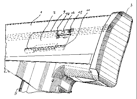
The object of the invention is explained in greater detail using an embodiment
example
and the attached schematic diagram. In its only drawing, the truncated, rear
part of a
semi-automatic rifle is shown which is constructed in the so-called Bullpup
configuration.
The rifle has a housing 1 that surrounds the breechblock and its path of
movement (not
shown). The housing 1 ends directly behind the aforementioned movement path. A
floor
CA 02444077 2003-10-10
plate 3 sits on the rear side of the housing l and thus borders directly the
rear end of the
path of movement of the breechblock. Thus, to a certain extent, the rear
property that is
most traditional in sporting rifles has been left out. On the underside of the
housing 1, a
magazine 5 is arranged near the floor plate 3. The handle piece (not shown
here) is
located in front of the magazine 5.
A first dust cover 7 is visible above the magazine 5. This dust cover 7 is
activated for
left-handed marksmen. A second dust cover for right-handed marksmen is
arranged on
the opposite side (hidden here) of the housing l and is a mirror image of the
first dust
cover 7.
The dust cover 7 covers an ejection opening 17. This opening is partially
visible here,
because the dust cover 7 is shown in a truncated manner. The dust cover 7 is
approximately rectangular. Beneath it and parallel to its underside edge, an
axle 11
extends around which the dust cover 7 swings by its underside. The free upper
edge 9 of
the dust cover 7 extends approximately parallel to this underside.
A continuous, multiply crimped, and highly ferromagnetic steel sheet metal
strip 13 is
inserted parallel to the upper edge 9 into the side of the dust cover the
faces the housing,
and specifically, such that because of its crimping, it emerges at least at
three points or at
the least lies extremely close under the surface. These points are close to
the front and
rear edge of the dust cover 7 and approximately in the middle of the upper
edge 9. The
strip 13 is manufactured together with the dust cover 7 in composite casting.
At least the
free parts of the strip 13 are treated on the surface (bonded, phosphatized,
or the like), in
order to prevent rusting.
Behind each point of the strip 13 where it emerges, a magnetic pin 15 is
inserted shut into
the wall of the housing 1 above the ejection opening. The magnetic pin 15
emerges by its
one facing surface or even projects a little above the embedded plastic of the
housing 1.
Magnetic pins 1 S and strips 13 are constructed and arranged so that they lie
flat on each
other when the dust cover 7 is closed.
On the whole, an inner contour of the opening 17 is constructed to complement
the outer
contour of the dust cover 7 (taking into account tolerances). Opposite this
inner contour,
however, the actual opening is made as a shoulder in the housing wall at least
in the area
of the magnet pins 15, so that the closed dust cover 7 sits on this shoulder,
but, in
addition, borders flush with the outer surface of the housing 1 (except for
the area of the
axle 11). Thus, interfering edges, which could lead to the untimely detachment
of the
magnetic lock, are avoided. An application of force from the outside, which
could cause
its untimely detachment, is also prevented.