Note : Les descriptions sont présentées dans la langue officielle dans laquelle elles ont été soumises.
CA 02444392 2003-10-03
LYM 501980
1
PUSH-TO-START APPLIANCE PROGRAM TIMER AND METHOD
UTILIZING SNAP-ACTION SWITCH
FIELD OF THE INVENTION
[0001] The present invention relates generally to appliance timer controls,
and more
particularly to timer control mechanisms and methods providing both timed
program
operation and start switch functionality.
BACKGROUND OF THE INVENTION
[0002] Consumer and commercial appliances, such as for example clothes dryers,
typically include some form of program timer that allows the user to select a
desired
operating cycle. In typical appliances, these program timers are embodied in a
motor driven
cam stack having a number of control switches that are operated via followers.
These
followers track one of the control faces on the cam stack. The selection of
the particular
program cycle is typically made via a rotary switch that is rotated to a
particular position
based on the graphics on the control panel of the appliance. This mechanical
interface to the
program timer control is familiar to consumers and provides a very simple user
interface.
Indeed, such a mechanical knob interface is still used in many electronic
controllers that
utilize a microprocessor to control the various operating cycles as opposed to
the rotating cam
stack.
[0003] Once the appropriate or desired program cycle is selected by the user,
the
appliance is started via actuation of a momentary contact switch. Typically,
this start switch
is a push button switch. Actuation of this nnomentary contact push button
start switch
energizes the start windings of the appliance's main motor. Once the motor
begins to rotate, a
centrifugal switch in the main motor actuates to maintain its energization.
The user is then
free to release the momentary contact push button start switch.
CA 02444392 2003-10-p3 . .
L ~M 501980
2
[0004) In one type of conventional appliance, the momentary contact push
button start
switch is integrated into the program cam stack controller. In such a
configuration, the
program selector knob is depressed to start the main motor of the appliance.
That is, in this
type of conventional appliance, the program selector knob is rotated to select
a desired
program cycle, and is then depressed momentarily to start the selected program
cycle.
[0005] Unfortunately, such a program timer with an integrated push button
start switch is
subject to misoperation by the user, resulting in shortened switch life and
erroneous program
operation. That is, because the momentary contact push button switch is
integrated into the
rotary control knob of the program timer, a user may inadvertently push in the
knob while
turning the knob to select a desired program cycle. If the knob is depressed
far enough while
rotating the knob to select a desired program cycle, the momentary contact
push button
switch may intermittently make contact. This energizes or attempts to energize
the start
winding of the appliance motor. This intermittent operation may damage the
appliance
motor, and may result in intermittent arcing between the switch contacts as
they are
intermittently connected and disconnected during the rotation of the switch.
This arcing may
damage and thus shorten the switch life itself.
[0006] Even if the momentary contact pushbutton switch is not actuated
intermittently
during rotation of the program timer control knob, the speed and consistency
at which the
user presses the control knob to start the appliance may still result in
intermittent or otherwise
inappropriate contact of the momentary contact push button switch. That is, if
the user were
to slowly depress the rotary knob the contacts may intermittently make and
break contact
numerous times before a firm contact is made. This will result in excessive
arcing between
the switch contacts and will shorten the life of the switch. Likewise, if the
user were to
withdraw the knob slowly once the appliance had been started, the slow
separation of the
electrical contacts ofthe momentary contact push button switch will draw and
sustain an
electrical arc. This will also serve to damage and thus shorten the life of
the program timer.
(0007) Recognizing the deficiency with the integrated program controller and
start
switch, many manufacturers employ an appliance control panel that separates
the program
timer control selection knob from the start switch. In such appliances, the
user first selects
02444392 2003-10-03
LYM 501980
3
the desired program cycle with the rotary program cycle select switch. Once
the appropriate
cycle has been selected, the user presses a separate momentary contact start
switch located on
the appliance's control panel. Unfortunately, while separating these two
functions eliminates
the intermittent starting of the appliance while the user is selecting a
desired program cycle,
the separate start switch is still subject to damage based on the manner in
which the user
depresses and releases the switch. That is, the arcing problem described above
resulting in
shortened life of the switch is still prevalent as the user may slowly depress
or slowly release
the separate start switch in a manner that results in arcing.
[0008] There exists, therefore, a need in the art for a program timer that can
perform the
appliance start function without the intermittent arcing problems currently
existing in the art.
BRIEF SUMMARY OF 'THE INVENTION
[0009] In view ofthe above, the present invention is directed to a new
and:improved
prograrri timer and method that overcome the above-described and other
problems existing in
the art. More specifically, the present invention is directed to a program
timer and method
that, in addition to program cycle timing functionality, also provide
appliance start
functionality without the adherent problems discussed above.
(0010] In one embodiment of the present invention the appliance start
functionality is
provided by a snap-action electrical switch that is actuated by the user
depressing the rotary
program timer knob. This knob is attached to the shaft of the program timer,
which in one
embodiment includes a switch activation wheel affixed thereto. This switch
activation wheel
is preferably larger in diameter than the cams of the cam stack. Upon
depression of the knob
by the user, the shaft and its associated wheel move a lever pivotally
positioned in relation
thereto to activate the snap-action switch to close the switch contacts.
Preferably, the shaft is
spring biased to its outward position such that upon release of the knob by
the user, the shaft
will be returned to its quiescent outward position. As the shaft and its
associated wheel are
returned to their quiescent position, the snap-action switch is allowed to
operate to open the
switch contacts.
CA 02444392 2003-10-03
LYM 501980
4
[0011] The extremely rapid action of the snap-action switch prevents the
teasing of the
switch contacts between the open and closed states. This prevents or minimizes
an
intermittent contact or sustained arc condition that could otherwise shorten
the life of the
switch. Further, the snap-action switch provides positional hysteresis to
prevent or minimize
any inadvertent, intermittent operation of the start functionality while the
user is rotating the
program selector knob to select the desired operating cycle of the appliance.
That is, once the
user has depressed the rotary knob a distance sufficient to actuate the snap-
action switch, the
knob must be released a significant distance, near its quiescent position,
before the snap-
action switch will operate to open the contacts. Further, the stored energy
that results in the
snap-action to both open and close the contacts results in a very rapid
transition between the
open and closed state such that arcing and localized high current flows at
only a portion of
the contact surface area is greatly minimized.
[0012] In a preferred embodiment of he present invention, a push-to-start
appliance
..program timer for use with an appliance comprises a housing, a program cam
stack defining
at least one program cycle, and a number of switches responsive to the program
cycle to
control operation of the appliance during the program cycle. The timer also
includes a shaft
in rotary driving engagement with the cam stack. This shaft is linearly
translatable within the
housing along an axis of the shaft through the cam stack. In this embodiment
the shaft
further includes an actuation wheel integrated with it. The timer further
includes a snap-
action start switch and an actuation lever positioned within the housing to
translate linear
movement of the shaft to actuate the snap-action switch. Preferably, the shaft
includes a user
interface knob operably coupled on one end external to the housing to rotate
the shaft and the
cam stack to select a program cycle. In this embodiment the wheel is operable
to translate
linear motion of the shaft to the lever at any rotary position of the knob.
[0013] In one embodiment the wheel has an outer diameter larger than an outer
diameter
of the cam stack. The snap-action start switch preferably includes an
actuation surface and a
push button. The actuation lever translates the linear movement of the shaft
to a normal
direction by sliding along this actuation surface to actuate the push button.
Preferably, the
timer further comprises a bias means for returning the shaft to a quiescent
position within the
CA 02444392 2003-10-03
LYM 501980
housing. In one embodiment the bias means comprises a spring positioned about
the shaft to
return the shaft to its quiescent position:
[0014] The snap-action start switch in one embodiment includes an
outwardlybiased
push button operably coupled through an actuation surface to the actuation
lever. The snap-
actuation start switch actuates to close its electrical contacts upon linear
translation of the
shaft to a first position. The snap-actuation start switch actuates to open
its electrical contacts
upon linear translation of the shaft to a second position. Preferably, the
first position and the
second position are not equal. In one embodiment, the first position and the
second position
are selected to provide positional hysteresis for actuation of the snap-action
start switch.
Preferably, the first positioni is selected to be proximate to a maximum
linear translation of
the shaft, and the second position is selected to be proximate to a quiescent
position of the
shaft. In one embodiment, the program control mechanism is a motor driven cam
stack
having a plurality of program cycles programmed thereon. This mechanism also
includes a
number of switches operating in response to the program cycles to control
operation of the
appliance. The program control mechanism may also be an electronic controller
having the : .
mechanical shaft user interface. Such controller may be microprocessor based.
[0015] In an alternate embodiment of the present invention, an appliance
program timer
comprises a shaft configured to accommodate a user interface knob affixed on
one of its ends,
a program control mechanism responsive to a rotary position of the shaft to
control operation
of an appliance, and a snap-action start switch responsive to a linear
translation of the shaft to
a first position to close its electrical contacts to begin a selected program
cycle and to a
second position to open its electrical contacts. Preferably, the first
position and the second
position are selected to provide linear positional hysteresis for the
actuation of the snap-
action start switch.
[0016] Preferably, the timer further comprises an activation lever pivotably
positioned to
translate linear motion in the shaft in a first direction to linear motion in
a normal direction to
activate the snap-action start switch. In one embodiment the shaft includes an
actuation
wheel integrated with it. In this embodiment linearmotion in the shaft is
translated to the
activation lever by the activation wheel regardless of a rotary position of
the shaft.
~ 02444392 2003-10-03
GYM 501980
6
Preferably, the timer further includes a bias means for linearly biasing the
shaft to a quiescent
linear position. In one embodiment, the bias means is a compression spring.
The shaft of this
embodiment of the invention is linearly translatable between the quiescent
linear position and
an inward depressed position. The first position is selected to be closer to
the inward
depressed position than the quiescent linear position; and the second position
is selected to be
closer to the quiescent linear position than the inward depressed position. In
another
embodiment wherein the shaft is linearly translatable between the quiescent
linear position
and an inward depressed position; the first position is selected to be
proximate to the inward
depressed position, and the second position is selected to be proximate to the
quiescent linear
position.
[0017] In a further embodiment of the present invention, a method of providing
a push-
to-start function in an appliance program timer having a shaft that is
rotatable to select a
desired program cycle and linearly translatable from an outward biased
position to an inward
depressed position to start the program cycle is presented. This method
comprises the steps
.of.providing a snap-action start switch, actuating the snap-action start
switch to close its
electrical contacts upon linear translation ofthe shaft to a first position,
and actuating the
snap-action start switch to open its electric contacts upon linear translation
of the shaft to a
second position.
[0018] Preferably, the step of actuating the snap-action start switch to close
its electrical
contacts upon linear translation of the shaft to the first position comprises
the step of
actuating the snap-action start switch to close its electrical contacts upon
linear translation of
the shaft to a first position proximate the inward depressed position. Also
preferably, the step
of actuating the snap-action start switch to open its electrical contacts upon
linear translation
of the shaft to the second position comprises the step of actuating the snap-
action start switch
to open its electrical contacts upon linear translation of the shaft to a
second position
proximate the outward biased position.
~ 02444392 2003-10-03
tv~.rso~9so
7
BRIEF DESCRIPTION OR THE DRAWINGS
[0019) The accompanying drawings incorporated in and forming a part of the
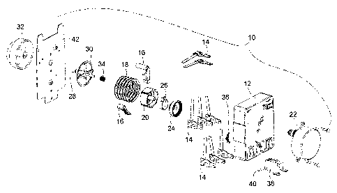
specification illustrate several aspects of the present invention, and
together with the
description serve to explain the principles of the invention. In the drawings:
[0020] FIG: 1 is an exploded isometric illustration of one embodiment of the
program
timer of the present invention;
[0021] FIG. 2 is a simplified top view illustration of the embodiment to the
present
invention illustrated in FIG. 1 illustrating relative positioning of the
components thereof;
[0022] FIG. 3 is a simplified cross-sectional illustration of the program
timer of FIG. 1
illustrated with its shaft in a quiescent position;
[0023] FIG. 4 is a simplified cross-sectional.illustration similar to FIG. 3
illustrated with
its shaft in an actuated depresses position;
[0024] FIG. 5 is an idealized graphical illustration relating program timer
shaft position
to the start switch contact state for both conventional momentary contact push
button switch
contacts and the snap-action start switch contacts of the present invention;
(0025] FIG. 6 is an idealized graphical illustration relating current flow
through a
conventional push button start switch to the program timer shaft position as
the shaft is
depressed to its fully actuated position;
(0026] FIG. 7 is an idealized graphical illustration relating current flow
through the snap-
action start switch of the present intention to the program timer shaft
position as the shaft is
depressed to its fully actuated position;
CA 02444392 2003-10-03
L ~M SOI980
8
[0027) FIG. 8 is an idealized graphical illustration relating current flow
through a
conventional push button start switch to the program timer shaft position as
the shaft is
returned to its quiescent position; and
[0028) FIG. 9 is am idealized graphical illustration relating current flow
through the snap-
action start switch of the present invention to the program timer shaft
position as the shaft is
returned to its quiescent position.
[0029] While the invention will be described in connection with certain
preferred
embodiments, there is no intent to limit it to those embodiments. On the
contrary, the intent
is to cover all alternatives, modifications and equivalents as included within
the spirit and
scope of the invention as defined by the appended claims.
DETAILED DESCRIPTION OF THE IN~IENTION
[0030) An exemplary embodiment of the push-to-start program timer 10 of the
present
invention is illustrated in exploded isometric form in FIG. 1. In such an
exemplary
embodiment having particular applicability to a consumer or commercial
appliance such as a
dryer, the assembly includes a housing 12 to accommodate the various sub-
assemblies that
perform the timing and switching functions of the appliance. The various
switch assemblies
14 are accommodated within the housing l2 and are actuated by actuators 16 in
accordance
with the operational program contained on the individual control cams of the
cam stack 18.
[0031] As is typical with a cam stack based program timer, the programmed cam
stack 18
is carried on a cam hub 20. The earn hub 20 is rotated by motor 22, which
drivingly engages
the cam hub through the drive hub 24 and a clutch spring 26. Alternatively,
the user may also
rotate the cam hub 20 via the user knob 32 which is coupled to the program
timer user shaft
28. As the user rotates the shaft 28 (via the user knob 32), the clutch spring
26 allows the
cam hub 20 to rotate without rotating the drive shaft of the motor 22 through
the drive hub
24. In this way the user may easily and quickly rotate the knob to select the
desired program
cycle. Once the cycle has been selected, operation of motor 22 will drive the
cam stack 18 to
CA 02444392 2003-10-03
L UM 501980
9
properly sequence the switch assemblies 14 (via actuators 16) to perform the
functionality
during the selected cycle.
(0032] In accordance with this embodiment of the present invention, the shaft
28 includes
therewith or attached thereto an actuation wheel 30. Preferably, this
actuation wheel 30 is of
a diameter larger than the diameter of the cams of the cam stack 18, the
reason for which will
be discussed more fully below. In this embodiment, the shaft 28 may be
linearly translated
from a quiescent position to an actuated position by a user who pushes on the
knob 32. Upon
release of the knob 32, a return spring 34 translates the shaft 28 back to its
quiescent position:
Of course, if a pull-to-start function is desired instead of a push-to-start
function, this
operation would be reversed. However, in the current embodiment, linear
actuation of the
shaft 28 also linearly translates the wheel 30, which then actuates the start
switch lever 36.
As will be discussed more fully below, actuation of the start switch lever 36
results'in
actuation of the snap-action start switch 38, which is held in place within
the housing 12 by a
start switch support pin 40. A cover 42 may be included to close the assembly
10, as desired.
(0033] The relationship between the various components of the assembly 10 may
be
better understood from the simplified top view illustration of FIG. 2. It will
be understood by
those skilled in the art that this FIG. 2 is a simplified illustration having
some components
removed from the housing 12. This simplified top view illustration shows the
relationship
between the larger diameter actuation wheel 30 as compared.to the individual
cams of cam
stack 18. In this way, the snap switch actuation lever 36 may be pivotally
positioned within
housing 12 so that linear actuation of the wheel 30 will allow it to act on
lever 36 without
interfering with the outer control surfaces of the cam stack 18. As the lever
36 is pivoted by
the linear actuation of wheel 30, it acts on the actuation mechanism of the
snap-action start
switch 38. The larger diameter of wheel 30 than the individual cams of cam
stack 18 allows
free pivoting of lever 36 without interference to the cam stack 18.
[0034] Turning now to FIGs. 3 and 4, the operational relationship between
wheel 30,
lever 36, and snap-action start switch 38 will be described as the shaft 28 is
linearly translated
between its outwardmost quiescent position (shown in FIG. 3) and its
inwardmost actuated
position (shown in FIG. 4).
- ~'~02444392 2003-10-03
LYM 501980
[0035] With specific attention to FIG. 3, the program timer of the present
invention 10 is
illustrated in its quiescent or normal program sequencing mode with the shaft
28 in its
outward most position. This position is maintained by the return spring 34. As
may be seen,
the wheel 30 is also in its quiescent or outwardmost position. The snap-action
switch 38
includes an activation mechanism comprised of an,actuation surface 44 and an
actuation push
button 46. The typical internal mechanism of the push button switch 38
maintains the push
button 46 in an outward position. The activation lever 36 is pivotally
attached within the
housing 12 such that it is in contact with the wheel 30 and the actuation
surface 44: That is,
return spring 34 maintains the shaft 28 and wheel 30 in their quiescent
position, while the
operation of the push button 46 and surface 44 maintain the lever 36 in its
quiescent position.
This is an effect of the outward bias of the pushbutton 46 by the snap-action
switch 38. In
this state, the motor 22 is free to rotate the cam stack 18; as is the user
through shaft 28,
without interference from the lever 36.
[0036] FIG. 4 illustrates the relationship between the elements of this
embodiment of the
program timer 10 of the present invention upon linear translation of shaft 28
to its inward,
actuated position. Such linear actuation typically occurs as a result of the
user depressing the
knob (not shown) to perform the push-to-start function enabled by the present
invention.
Upon such linear actuation, the lever 36 is caused to pivot by the linear
translation of wheel
30 under action of the user. This pivoting of lever 36 causes one end of this
lever 36 to slide
upon actuation surface 44, which results in the inward depression of the push
button 46 of the
snap-action switch 38. That is, the downward linear translation of the shaft
28 in the
orientation of FIG. 4 results in an outward displacement of surface 44 and
push button 46.
This translation from linear motion in one direction to linear motion in a
normal direction
provides 'packaging efficiencies which allow the addition of the push-to-start
functionality
without the requirement that the overall package of the assembly be increased.
[0037] While the above describes the construction of one embodiment of the
present
invention, the following discussion of FIGS. 5-9 is concerned with the
functionality and
advantages provided by the use of the snap-action switch to provide the push-
to-start
functionality for a consumer or commercial appliance, e.g. a dryer.
,::y 02444392 2003-10-03 .
L UM 501980
11
[0038] FIG. 5 is a graphical illustration relating the position of the shaft
28 to the opening
and closing of a conventional momentary contact push button switch as
described in the
background of the invention section above, and to the snap-action switch
contact position for
the snap-action switch 38 utilized in the program timer of the present
invention. Initially, the
shaft of the program timer is in its quiescent or released position as
indicated at time to. At
time t1, however, the shaft 28 is slowly linearly actuated by a user from its
released position
to its fully actuated or depressed position, which is reached at time t3. The
shaft 28 is held in
its fully depressed position until time t4 at which point it is slowly allowed
to return to its
fully released or quiescent position at time t6.
[0039] In conventional program timers that implement the push-to-start
function, the
contacts of the momentary contact push button switch remain open until the
program timer
shaft is fully depressed as indicated by trace 52 which transitions from an
open to a closed
position at time t3. Similarly, the contacts of the conventional momentary
contact push
button switch are:immediately opened upon initial withdrawal of the shaft as
indicated by
trace 52 at time t4. That is, with a conventional program timer, the contacts
of the start switch
do not touch until the shaft is fully depressed; and no longer touch once the
shaft begins to
return to its quiescent state. There is no difference between the linear
position of the shaft at
which the contacts open and close.
[0040] Unlike the traditional push button momentary contact switch; the snap-
action
switch 38 of the present invention provides positional hysteresis for the
opening and closing
of its electrical contacts. This may be seen from trace 54 of FIG. 5.
Specifically, as the shaft
28 is depressed beginning at time t1, the lever 36 will begin to push on
surface 44 (see FIG. 4)
depressing push button 46 and supplying potential energy to the snap-action
switch 38. At a
time t2, the amount of potential energy inputted to the snap-action switch 38
will be sufficient
to operate the snap-action contacts resulting in their rapid closure at time
t2. The linear
position at which such snap-action actuation occurs may be selected to be near
the end of the
linear travel of shaft 28, or indeed, at any point along this travel as
desired. The positional
hysteresis is illustrated as the shaft 28 is released beginning at time t4. As
illustrated by trace
54, the contacts of the snap-action switch 38 remain closed until a linear
position is reached
CA 02444392 2003-10-03
LYM 501980
12
at time is when, once again, enough potential energy has been stored within
the snap-action
switch 38 to actuate the snap-action mechanism to open the contacts. The
linear position at
which this snap-action actuation occurs may be varied as desired. In a
preferred embodiment
this actuation will occur near the fully released position of the shaft 28.
However it may be
selected to be anywhere along the linear position of the shaft 28 as desired.
[0041] By providing the positional hysteresis for actuation of the snap-action
start switch
38, the starting function will only be performed upon deliberate depression of
the shaft 28,
and will remain in operation until deliberate release of the shaft 28. This
opening and closing
of the start switch contacts at two different linear positions of the shaft 28
will preclude the
intermittent and switch life shortening operation as is common in conventional
push-to-start
switches where any hand fitter or palsy ofthe operator will result in multiple
switch openings
and closures.
[0042] The significant difference in operation between the conventional
momentary
contact push button switch and the snap-action start switch 38 of the present
invention may
be better understood through an analysis of the arcing and current flow
between the contacts
under both opening and closing conditions: With attention first to FIG. 6,
there is illustrated
an idealized graphical illustration of the shaft position 50 in the current
flow between the
contacts of the conventional momentary contact push button switch represented
by trace 56.
As may be seen; as the shaft of the program timer is linearly depressed
beginning at time t1,
the contacts of the conventional momentary contact push button switch also
linearly track this
position so that they are coming in closer proximity as the shaft is
depressed. At some point
designated to the contacts of the conventional switch will be close enough
such that the
electrical potential across the contacts will overcome the dielectric strength
of the air in the
switch, resulting in an electrical arc between these two contacts. This arc
will continue and
increase in current flaw until the two contacts are fully closed as
represented at time t3. As is
recognized by those skilled in the art, this arc will result in the
accumulation of carbon and
damage to the switch contacts themselves.
[0043] In contrast to the operation of the conventional push button switch
illustrated in
FIG. 6, FIG. 7 illustrates the same linear translation of the shaft 28 of the
program timer of
CA 02444392 2003-10-03
LVM 501980
13
the present invention and the resulting current flow between the contacts of
the snap-action
switch 38. The linear translation of the shaft illustrated by trace 50 has no
effect on the
physical spacing between the contacts of the snap-action switch 38. That is,
operation of the
snap-action switch described above initially results in the supplying of
potential energy to the
snap-action switch 38. Once a sufficient amount of potential energy is induced
into the snap-
action switch 38, its snap actuation occurs as illustrated at time t2. As may
be seen in this
idealized FIG. 7, there is no significant pre-contact arcing between the
contacts as is the case
with the conventional switch. This is because the contacts are very rapidly
transitioned
between their fully opened and fully closed position as a result of the snap
actuation of the
switch 38. The storage of the potential energy and converting of that
potential energy to a
snap closure of these contacts precludes the sustaining of any arc during this
closing
operation.
[0044] While the closing of the conventional push button switch can present an
arcing
problem if the user depresses the knob of the program timer very slowly, a
more significant
arcing problem occurs when the user releases or withdraws the knob of the
program, irner as
illustrated in FIG. 8. As may be seen in this FIG. 8, the current flow between
the contacts of
the conventional push button switch illustrated as trace 56 is initially at
its maximum while
the contacts are closed. However, at time t4 the user begins to release the
knob of the
program timer as illustrated by the increasing distance represented by trace
50. Since current
is already flowing between the two contacts, the beginning of separation of
these contacts
draws a substantial arc which will be sustained, albeit diminishing in
magnitude, until a time
te. This time is significantly longer than the arc drawn upon closing, and
results in a much
greater accumulation of carbon and the significant potential for localized
heating and melting
of the metal of the contact surface. The amount of this type of damage is
significantly
increased the slower the user allows the knob to return to its quiescent
position. Further,
since there is no positional hysteresis of the opening and closing of the
switch contacts, any
teasing of the switch (i.e. maintaining the switch contacts in close physical
proximity and
occasionally allowing them to touch) results in significant damage to the
switch contacts,
greatly shortening the life and increasing the cost of ownership of the
appliance.
~ 02444392 2003-10-03
LVM 501980
14
[0045] In contrast to the use of the conventional push button switch, the use
of the snap-
action switch 38 in the program timer 10 of the present invention
significantly reduces or
eliminates the drawing of an arc upon opening of the switch as illustrated in
FIG. 9. As
discussed above, since the linear position of the switch relates only to the
amount of potential
energy supplied to the snap-action switch 38, and not to the physical
proximity of the switch
contacts themselves. The increasing linear position of the shaft represented
by trace 50 does
not affect the current flow 58 through the contacts of the snap-action switch
until an amount
of potential energy sufficient to result in actuation of the switch 38 is
supplied. As illustrated
in this FIG. 9, this point, is reached at a time is at which point the snap
actuation of the
contacts occurs to. rapidly separate the two contacts. While an arc may well
result between
the contacts upon their opening; the speed at which the snap actuation occurs
will minimize
the potential for any contamination or damage to the switch contacts
themselves. Indeed, the
rapid separation of the switch contacts will completely or nearly remove any
potential for
melting of any portion of the switch contact material due to localized heating
caused from a
sustained electrical arc. As such, the use of the snap-action switch 38
provides significant
advantages both in overall system operation and component lifetime.
[0046] All references, including publications, patent applications; and
patents, cited
herein are hereby incorporated by reference to the same extent as if each
reference were
individually and specif cally indicated to be incorporated by reference and
were set forth in
its entirety herein.
[0047] The use of the terms "a" and "an" and "the" and similar referents in
the context of
describing the invention (especially in the context of the following claims)
are to be
construed to cover both the singular and the plural, unless otherwise
indicated herein or
clearly contradicted by context. The terms "comprising," "having;"
"including," and
"containing" are to be construed as open-ended terms (i.e., meaning
"including, but not
limited to,") unless otherwise noted. Recitation of ranges of values herein
are merely
intended to serve as a shorthand method ofreferring individually to each
separate value
falling within the range, unless otherwise indicated herein, and each separate
value is
incorporated into the specification as if it were individually recited herein.
All methods
described herein can be performed in any suitable order unless otherwise
indicated herein or
02444392 2003-10-03
LVM 501980
otherwise clearly contradicted by context: The use of any and all examples, or
exemplary
language (e.g., "such as") provided herein, is intended merely to better
illuminate the
invention and does not pose a limitation on the scope of the invention unless
otherwise
claimed. No language in the specification should be construed as indicating
any non-claimed
element as essential to the practice of the invention.
[0048] Preferred embodiments of this invention are described herein, including
the best
mode known to the inventors for carrying out the invention. Variations of
those preferred
embodiments may become apparent to those of ordinary skill in the art upon
reading the
foregoing description. The inventors expect skilled artisans to employ such
variations as
appropriate, and the inventors intend for the invention to be practiced
otherwise than as
specifically described herein. Accordingly, this invention includes all
modifications and
equivalents of the subject matter recited in the claims appended hereto as
permitted by
applicable law. Moreover, any combination of the above-described elements in
all possible
variations thereof is encompassed by the invention unless otherwise indicated
herein or
otherwise clearly contradicted by context.