Note : Les descriptions sont présentées dans la langue officielle dans laquelle elles ont été soumises.
CA 02445326 2006-08-22
1
Method for controlling a winder
The invention relates to a method for controlling a winder.
In this description, stopping means control of the speed of a winder such that
the set target speed is reached at the same instant as the set target length
or
target diameter in a paper roll being completed or, alternatively, in a paper
roll
being unwound. If the target speed is zero, the winder stops, but otherwise it
continues to run at a new target speed which is slower than the normal
io running speed.
When a paper or board web that is being completed is wound into a paper roll
for customers, paper rolls having a certain diameter or a certain web length
are usually needed. Consequently, in the winding process it must be known
before the winding is stopped at what stage the winding shall be stopped in
order that the roll being completed shall be a roll having a desired diameter
or
a desired number of metres of web, in which connection in the control of
winding it is necessary to know the stopping distance, i. e. the number of
metres of web still to be run if stopping is started at the instant in
question.
2o Another need of stopping arises when deceleration is performed at a certain
location of the roll being unwound (typically a defective area in the roll
being
unwound) or when there is stopping at the bottom of the roll being unwound
before the end of the web is able to be unwound from the roll. The stopping
distance is calculated on the basis of an estimated stopping length and the
number of remaining metres (target length less actual length) and, in prior
art
applications, a speed reference is supplied based on this to a rounder, on the
basis of which a speed reference is supplied to the drive and, based on this
calculation, the set value of speed passed to the rounder is changed upward
or downward to control the speed such that winding can be stopped at a
3o desired roll size. This control method known from the state of the art is
relatively coarse.
CA 02445326 2006-08-22
2
In the prior art arrangements, when stopping takes place according to roll
diameter, the paper caliper provided by density measurement has been used
in calculation. In the prior art applications, pulse measurements, which are
inaccurate and unreliable measurements, have been used in diameter and
density measurements.
Moreover, in the prior art methods, taking the delay of the drive into account
in
the calculation of the estimated stopping length has been somewhat
complicated and, in addition, inaccuracies have occurred, in particular if it
has
io been necessary to start deceleration in a situation in which the machine is
still
accelerating or it has already been in a deceleration phase for some other
reason.
In the prior art applications, a "bang-bang" control has been used in
is controlling deceleration in stopping: either the target value of speed or
the
target value of deceleration has been switched between two values, and an
instantaneous deceleration value has been formed as a mean value. These
are coarse and inaccurate means for deceleration control.
20 With respect to the prior art, reference is made to Fl patent No. 80432
(corresponding US patent No. 4,631,682), which discloses a method for
controlling the operation of a winder, the control system described in the
patent providing automatic control of slitter-winder deceleration and stopping
at a preset sheet length or a preset roll diameter. This system has used a
25 closed loop control of speed deceleration and automatic compensation for
layers removed after a sheet break. This method has been based on the use
of two different deceleration values, one of them being used for achieving a
desired stopping distance. This prior art method is rather coarse.
3o The present invention is directed towards the provision of a method in
which
the calculation of the stopping distance of a winder is more accurate than
CA 02445326 2008-10-24
3
parameters used to have different values (acceleration, deceleration,
roundings and
end speed).
The present invention also is directed towards the provision of a method for
controlling the winder which does not have the problems of the prior art
arrangements
and which is more versatile as to its possibilities of use.
In accordance with one aspect of the present invention, there is provided a
method for
controlling a winder, in which method the stopping of the winder is controlled
such
that winding is stopped when a desired length of a web has been wound on a
roll
being formed/unwound from a formed roll or when the desired size of the
diameter of
the roll is reached, in which method an estimated stopping length is
calculated based
on speed, acceleration and a desired end speed, wherein, in the method, the
estimated
stopping length is calculated by means of a program based on speed,
acceleration and
the desired end speed as well as rounding times.
In accordance with advantageous features of the method of the invention, when
used,
the calculation of the number of metres still to be run when stopping is
started at the
instant in question, i. e. the calculation of the stopping distance is more
accurate than
it is in the prior art applications because in it the estimated length is
calculated from
instantaneous speed, target speed, rounding times, measured instantaneous
acceleration/deceleration, target deceleration and drive delay.
The method in accordance with advantageous additional features of the
invention
allows the parameters used (acceleration, deceleration, roundings and end
speed) to
have different values. In accordance with advantageous features of the
invention, in
the calculation of the stopping distance, the actual acceleration value is
used which is
obtained by differentiating the actual speed value by means of a program. This
provides a substantial improvement from the point of view of the control of
stopping
because, when the drive delay is long, the number of metres caused by the
rounding
time of actual deceleration becomes a considerable addition to the estimated
stopping
length.
In the method in accordance with advantageous additional features of the
invention,
deceleration is solved iteratively based on the estimated stopping length
CA 02445326 2003-10-24
WO 02/088012 PCT/FI02/00328
4
and the number of remaining metres (target length - actual length), thereby
achieving correct stopping. The thus obtained reference value deceleration is
passed to the rounder of the speed reference, which calculates the speed
reference
to be passed to the drive. When desired, the deceleration reference can also
be
passed directly to the drive. In the method, the speed reference is formed for
the
drive such that the rate of change of acceleration/deceleration is constant =
target
deceleration / rounding time. Acceleration is constant, but deceleration can
vary
according to stopping calculation. The rounding times may have different
target
values in the starting and stopping of deceleration.
An exception to these rules is a situation where the phase of controlled
deceleration is not reached but the speed reference is at rounding during the
whole
time of deceleration. This situation may arise when the change of speed is
small
and the rounding times are long. In this situation, iteration cannot solve the
deceleration value because there is no time to reach it, but, instead, it
solves the
values of starting/end rounding, by means of which correct stopping is
achieved.
Alternatively, in the method in accordance with the invention, to determine
deceleration, the deceleration could be explicitly solved from an estimated
stopping length equation, by which the same end result is obtained in
practice.
However, an iterative arrangement is used in an advantageous embodiment of the
invention because programwise it is simpler and easier to understand.
Iteration
can be considered to be a unit controller of deceleration or, alternatively, a
stochastic approximation.
When the method in accordance with the invention is used for stopping
according
to a desired diameter, the remaining diameter difference is converted into the
number of remaining metres for calculating the estimated stopping length. This
takes place by using measured diameter, core diameter and measured length by
means of proportions. Thus, determination is simple and reliable in operation.
The
error which is found in the calculated value and which comes from diameter
CA 02445326 2003-10-24
WO 02/088012 PCT/FI02/00328
measurement becomes smaller towards the end and the stopping method
compensates for it effectively, enabling accurate stopping even though there
would be noise in measurements. The target diameter is converted into a target
length as follows:
5
Stop length = Measured length =(Stop diameter2 - Core diameter2)
(Measured diameter2 - Core diameter)
The stopping method in accordance with the invention enables accurate stopping
at any desired end speed such that, when reaching the end speed, the target
diameter or the target length is reached. The end speed can be, for example,
zero,
the speed during roll change in winding or a desired deceleration rate in
unwinding w11en passing an area of poor quality.
In the stopping method in accordance with the invention, stopping can be
accomplished accurately also in the case when deceleration has to be started
when
the machine is still accelerating or when it is already decelerating for some
other
reason. This is based on the accurate calculation of the estimated stopping
length
described above and advantageously on the use of the actual acceleration value
in
it.
In the stopping method in accordance with the invention, the drive delay is
taken
into account in calculating the estimated stopping length by adding it to the
stopping time (multiplied by two). This is a significant improvement also when
accelerating while stopping is going on.
In accordance with an advantageous additional feature, the stopping method in
accordance with the invention can itself measure the drive delay every time
the
machine perforins acceleration or deceleration at a constant acceleration
rate. In
the method in accordance with the invention, the drive delay is the only
tuning
parameter that is thus automatically obtained in the method as measured by the
program itself. Thus, tuning is quick and reliable, and the measured drive
delay
CA 02445326 2003-10-24
WO 02/088012 PCT/FI02/00328
6
shows at the same time how well the drive follows the speed reference. The
variable deceleration rate used in the method makes the inertia compensation
of
the drive in unwinding for tension control somewhat more difficult. This
problem
has been advantageously solved such that on the drive side there is always a
filter
in the handling of the speed reference, wliich, on the one hand, limits
changes in
speed and, on the other hand, provides an accurate deceleration value for
inertia
compensation. Here, it is possible to advantageously use, for example, a 4-
second
Finite Impulse Response filter, which provides a drive delay of about 2
seconds
and enables good operation of stopping.
In the invention, reaching the target deceleration rate is based on the fact
that, in
accordance with an advantageous additional feature, stopping is started at the
correct instant, including the drive delay. If the instant of starting
deceleration is
delayed, for example, because of an error in diameter measurement, the final
stopping is nevertheless still accurate, but in that case the reference
deceleration
solved by iteration will be higher than the target value. Similarly, the
deceleration
started too early leads to a lower deceleration rate. If in connection with
the
method in accordance with the invention, accurate stopping is desired based on
unreliable measurements, the value of the absolute maxiinum deceleration is
used
which is slightly higher than the target deceleration.
In the method in accordance with the invention, the stopping of the winding
process is advantageously performed based on the diameter provided by linear
sensors of winding stations and on the web length received from pulse
measurement. When the method in accordance with the invention is used in
connection with unwinding, stopping operations can be performed without pulse
measurements if the exact diameter is available which has been measured, for
example, by a ultrasonic sensor.
In the automatic stopping method in accordance with the invention, the
estimated
length is advantageously calculated first based on speed, acceleration,
rounding
CA 02445326 2003-10-24
WO 02/088012 PCT/FI02/00328
7
times and end speed. The estimated length obtained indicates how many web
metres would still accumulate if stopping started now. After that, a
comparison is
made whether the calculated estimated length is equal to or greater or less
than the
number of remaining metres or whether stopping is going on. If the situation
does
not yet call for it, the desired running speed is maintained. If the number of
remaining metres is smaller than the estimated stopping length, stopping is
started
and the desired end speed is set as the target speed instead of the running
speed.
After that, the estimated length and the number of remaining metres are again
compared with each other and, based on the result obtained, the deceleration
rate
is either increased or decreased. If the calculation of the estimated length
shows
that there is no time to reach this deceleration value, a corresponding
increase/decrease is made to rounding times. After that, a rounded speed
reference
value is generated for the electric drive, using the target speed, the
reference
deceleration rate/reference acceleration rate and the desired end speed as
reference
values. When the target has been reached, i.e. the number of remaining metres
is
zero, stopping and the number of metres run are zeroed and, when commanded,
running is re-started. The control cycles according to the invention are
carried out
at desired intervals using, for example a cycle of 100 ms.
In the following, the invention will be described in greater detail with
reference to
the figures of the accompanying drawing, but the invention is by no means
ineant
to be narrowly confined to the details of the figures.
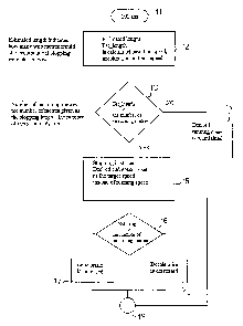
Figures 1A and 1B show schematic block diagrams of the automatic stopping
method in accordance with the invention.
Figure 2 shows curves on a graph concerning speed reference, actual speed as
well as acceleration reference and actual acceleration values.
Figure 3 shows deceleration during stopping as curves on a graph.
CA 02445326 2003-10-24
WO 02/088012 PCT/FI02/00328
8
As shown in Figs. lA and 1B, an automatic stopping cycle between blocks 11 and
23 is always carried out after a desired interval using, for example, a cycle
of 100
ms. In the bloclc 12, an estimated length is calculated based on speed,
acceleration
and end speed. The estimated length indicates how many web metres would still
accumulate if stopping started now. In the bloclc 13, the estimated length is
compared with the number of remaining metres and it is cliecked whether
stopping is already going on. If this is not the case, there is a transition
to the
block 14 and the desired running speed is maintained. If the estimated length
is
greater than the number of remaining metres or if stopping is already going
on,
there is a transition to the block 15 and stopping is started / stopping is
continued
and the desired end speed is set as the target speed instead of the running
speed.
The number of remaining metres means the number of metres given as the
stopping target less the number of metres already run. In the block 16, the
estimated length is compared with the number of remaining metres and, in
accordance with it, either the block 17 or 18 is chosen and deceleration is
increased or decreased according to whether the estimated length is greater or
smaller than the number of remaining metres. After the block 19 there is a
transition to the bloclc 20, in which a rounded speed reference value is
formed for
the electric drive by using the target speed, the reference
deceleration/acceleration
and the desired end speed as reference values. In the block 21, it is checked
whether the target has already been reached, i.e. whether the nuinber of
remaining
metres is equal to zero. If this is not the case, there is a transition to the
next cycle
through the block 23. If the target has been reached, stopping and the number
of
metres run are zeroed and, when commanded, running is re-started.
In the method in accordance with the invention, calculation is carried out
using
the following formulas in accordance with the block diagram described above.
CA 02445326 2003-10-24
WO 02/088012 PCT/FI02/00328
9
.-,
~
ti
C.1 Z =
Nh/N ry
+ 0 O
`1V
=~ ~v y
=1 V I N
=~ r O
=
y = =N
I c ^ =
~ r v bo
II o a c
=~ ^~ ~
bo
+ ~ UI
~-~ " 0 =
=
~ + q til to
o N I ~u v
~ w o ~ o ~C o
N ~I
~C c~, ,~ b-0 =~
bo
.~ ~ ~ = m
.Naa ~ o
h
I N =
c. =. .~; ti Cv .~ ',^~.
V I ~ O +""+ CS (~ ~ ~ >.r
- q ~ o
z =~ õ ~ ~ ~ I C =
~ =~ q =~ ~ q a ~i ~; I ,~ q ,~ a
~ ~ v ^ I ~ ~, II W
~ yo =~IN -'IN ~ ~, I N
b Iz
a~ a~ v
c/)
CA 02445326 2003-10-24
WO 02/088012 PCT/FI02/00328
.-,
0
~
~
U
N
v
+,.
bA
-I-
~ ti
O
^=~ r~=
V I
Z"
N '~v
U =
N " a0 a~
+
= O
N O C O
b0 = +~
cy N ti
v U ~
+I ,~ _ ~ o
^~ O
U o ^'
"v
,=~= N .,, ,,, hA
~
+
o ,y p ^ =~; a~
H ^I U - ^~ ~ O
U N py b~4 6 Q.
y bo = o~ ~ N W Q, ~
Z.
bi)
o .v =
~ ^~ = ~ ~ ~ ~ o~
= ~ ~ ~p
y ? fi~ . N G u
g."
as a~
j ^~ ^ ti
~=Lcn
zzt
ct C L". ~_ q '- c, =+~
c13 i.p.+
cz
bo
tu cj ~ = o
y cn
V .-I `~~= 'o'--~~ N N
A ~ y ~, `~' ~ Q + E" N
CA 02445326 2003-10-24
WO 02/088012 PCT/FI02/00328
11
o I~
Ci b4 ~-
G'
~ =~
~IM I ! + N
u = O
+ .O v =
'tv =~ 'V ~ v e~v
b~o
v~ ~ p~ q N L U
C = I I ~D Q
U v T bo
= I = Q
obO
~O bO
= c.t N v I
~}N o o Nbp
m rl Cj a L t
o ~o v = ~ ! c
cs '~t v v ~. = o, .?
.~ ,~ ~,! =o ~ Q I~
o I I
"~ ~t ~, =
Zs I ce c~ q o~i o
~ II II ~ II ~!
.C I! r r
CA 02445326 2003-10-24
WO 02/088012 PCT/FI02/00328
12
Fig. 2 shows curves relating to a speed reference and actual speed as well as
to an
acceleration reference and actual acceleration. The Y axis represents speed
and
acceleration (figures multiplied by a thousand) and the X axis represents
running
time. The reference numeral 35 designates the instant when stopping is started
and
the reference numeral 36 designates a situation in which the target has been
reached. In accordance with the speed reference of the curve 31, the actual
speed
values 32 follow the speed reference. The point indicated by the reference
numeral 37 shows how the electric drive follows the speed reference as a
slave.
The actual acceleration curve is designated by the reference numeral 33 and
the
acceleration reference is designated by the reference numeral 34. The point 38
shows how there is measurement noise in acceleration conditions, and the
reference numeral 39 designates a situation in which the acceleration
reference is
controlled in accordance with stopping. As seen from the curves, the actual
speed
value follows the speed reference very well and the actual acceleration value
also
follows the acceleration reference very well. The curves in Fig. 2 have been
shifted in the vertical direction to improve readability.
Fig. 3 schematically shows deceleration during stopping, the Y axis
representing
deceleration and the X axis representing running time. In otller words, this
is, in a
way, a partial enlargement of the end situation shown in Fig. 2 in which the
curves 31, 32, 33, 34 are placed in their correct positions without a vertical
shift.
In the situation of Fig. 3, the target deceleration has been -0.4, and the
point 41
shows how deceleration has been reduced in order not to run past the set
target
value.
Above, the invention has been described with reference to some of its
advantageous embodiments only, but the invention is by no means intended to be
narrowly confined to the details of the embodiments.