Sélection de la langue

Search

Sommaire du brevet 2446359 

Énoncé de désistement de responsabilité concernant l'information provenant de tiers

Une partie des informations de ce site Web a été fournie par des sources externes. Le gouvernement du Canada n'assume aucune responsabilité concernant la précision, l'actualité ou la fiabilité des informations fournies par les sources externes. Les utilisateurs qui désirent employer cette information devraient consulter directement la source des informations. Le contenu fourni par les sources externes n'est pas assujetti aux exigences sur les langues officielles, la protection des renseignements personnels et l'accessibilité.

Disponibilité de l'Abrégé et des Revendications

L'apparition de différences dans le texte et l'image des Revendications et de l'Abrégé dépend du moment auquel le document est publié. Les textes des Revendications et de l'Abrégé sont affichés :

  • lorsque la demande peut être examinée par le public;
  • lorsque le brevet est émis (délivrance).
(12) Brevet: (11) CA 2446359
(54) Titre français: SECHEUSE APPAREIL ET METHODE POUR SECHER LE LINGE
(54) Titre anglais: CLOTHES DRYER APPARATUS AND METHOD
Statut: Périmé et au-delà du délai pour l’annulation
Données bibliographiques
(51) Classification internationale des brevets (CIB):
  • D06F 58/38 (2020.01)
  • D06F 58/08 (2006.01)
(72) Inventeurs :
  • RIDDLE, DOUGLAS ALLEN (Etats-Unis d'Amérique)
  • GREEN, JEREMY MICHAEL (Etats-Unis d'Amérique)
  • MEYER, JAMES ALAN (Etats-Unis d'Amérique)
  • ABI-HABIB, EMILE EDWARD (Etats-Unis d'Amérique)
  • HAMEED, ZUBAIR (Etats-Unis d'Amérique)
(73) Titulaires :
  • GENERAL ELECTRIC COMPANY
(71) Demandeurs :
  • GENERAL ELECTRIC COMPANY (Etats-Unis d'Amérique)
(74) Agent: CRAIG WILSON AND COMPANY
(74) Co-agent:
(45) Délivré: 2010-12-14
(22) Date de dépôt: 2003-10-23
(41) Mise à la disponibilité du public: 2004-12-27
Requête d'examen: 2008-09-26
Licence disponible: S.O.
Cédé au domaine public: S.O.
(25) Langue des documents déposés: Anglais

Traité de coopération en matière de brevets (PCT): Non

(30) Données de priorité de la demande:
Numéro de la demande Pays / territoire Date
10/608,044 (Etats-Unis d'Amérique) 2003-06-27

Abrégés

Abrégé français

Sécheuse pour sécher des articles par culbutage, comprenant un tambour dont la cavité est conçue pour contenir les articles à sécher, un premier moteur d'entraînement couplé au tambour qu'il fait tourner, une source de chaleur en communication avec la cavité, ainsi qu'un moteur à vitesse variable qui entraîne un ventilateur auquel il est couplé. Le ventilateur est placé de façon à envoyer de l'air chauffé par la source de chaleur vers la cavité.


Abrégé anglais

A dryer for tumble drying articles includes a drum including a cavity configured to hold articles to be dried, a first motor drivingly coupled to the drum to rotate the drum, a heat source in flow communication with the cavity, and a variable speed motor drivingly coupled to a blower positioned to deliver heated air from the heat source to the cavity.

Revendications

Note : Les revendications sont présentées dans la langue officielle dans laquelle elles ont été soumises.


WHAT IS CLAIMED IS:
1. A dryer for tumble drying articles comprising:
a drum comprising a cavity configured to hold articles to be dried
a first motor drivingly coupled to said drum to rotate said drum;
a heat source in flow communication with said cavity; and
a variable speed motor drivingly coupled to a blower positioned to
deliver heated air from said heat source to said cavity.
2. A dryer in accordance with Claim 1 further comprising a control
operatively coupled to said variable speed motor to control at least one
operating
parameter of said variable speed motor in a fixed state.
3. A dryer in accordance with Claim 2 wherein said operating
parameter is motor speed.
4. A dryer in accordance with Claim 2 wherein said operating
parameter is motor torque.
5. A dryer in accordance with Claim 1 further comprising:
an outlet duct in flow communication with said cavity; and
a pressure sensor positioned to sense air pressure within said duct, said
sensor configured to generate a signal representative of the sensed air
pressure.
6. A dryer in accordance with Claim 5 further comprising a controller
responsive to the signal from said pressure sensor operationally coupled to
said
pressure sensor.
7. A dryer in accordance with Claim 2 further comprising a
temperature sensor positioned to sense an air temperature associated with said
cavity,
said sensor configured to generate a signal representative of the sensed air
temperature.
8. A dryer in accordance with Claim 7 further comprising a controller
responsive to the signal from said temperature sensor operationally coupled to
said
temperature sensor.
-7-

9. A dryer in accordance with Claim 7 further comprising an air inlet
in flow communication with said cavity positioned between said cavity and said
heat
source, said temperature sensor positioned within said air inlet.
10. A dryer in accordance with Claim 7 further comprising an air
outlet in flow communication with said cavity, said temperature sensor
positioned
within said air outlet.
11. A dryer in accordance with Claim 1 wherein said variable speed
motor comprises a self governing motor.
12. A blower control system for a tumble type dryer having a variable
speed blower motor driving the blower to supply heated air to the dryer cavity
through
a cavity inlet and exhaust air from the dryer cavity through a cavity outlet,
said system
comprising:
at least one temperature sensor positioned to sense a temperature
associated with the dryer and configured to generate a temperature signal
representative of the sensed temperature;
at least one pressure sensor positioned to sense a pressure associated
with the dryer and configured to generate a pressure signal representative of
the
sensed pressure; and
a controller operatively coupled to said at least one temperature sensor
and said at least one pressure sensor and configured to receive the
temperature and
pressure signals and control the operation of the variable speed blower motor
based on
at least one of the received signals.
13. A blower control system in accordance with Claim 12 wherein the
temperature signal is representative of cavity inlet air temperature.
14. A blower control system in accordance with Claim 12 wherein the
temperature signal is representative of cavity outlet air temperature.
15. A blower control system in accordance with Claim 12 wherein
said controller regulates the operation of the variable speed blower motor
based on the
temperature signal to maintain a substantially constant inlet air temperature
setpoint
for the cavity.
-8-

16. A blower control system in accordance with Claim 12 wherein
said controller is configured to receive a signal representative of clothes
load and
regulate the operation of the variable speed blower motor based on the clothes
load
signal.
17. A blower control in accordance with Claim 12 further comprising
an inverter operatively coupled to the variable speed blower motor and
configured to
control an operating parameter of the variable speed blower motor.
18. A blower control in accordance with Claim 17 wherein said
controller controls a duty cycle of said inverter.
19. A blower control in accordance with Claim 18 wherein said
operating parameter is motor speed.
20. A blower control in accordance with Claim 18 wherein said
operating parameter is motor torque.
21. A method for controlling a variable speed blower for a clothes
dryer, said method comprising:
installing a controller on the dryer in communication with at least one
temperature sensor and at least one pressure sensor;
receiving a signal in the controller from the at least one temperature
and pressure sensors; and
controlling the blower motor based on at least one of the received
temperature and pressure signals.
22. A method in accordance with Claim 21 wherein said controlling
the blower motor further comprises controlling the blower motor based on a
dryer
load size.
23. A method in accordance with Claim 22 wherein said controlling
the blower motor further comprises controlling the blower motor to maintain a
substantially constant inlet air temperature setpoint for the dryer.
24. A method in accordance with Claim 22 wherein said controlling
the blower motor comprises controlling a duty cycle of an inverter
operationally
coupled to the blower motor.
-9-

Description

Note : Les descriptions sont présentées dans la langue officielle dans laquelle elles ont été soumises.


09HL19991
CA 02446359 2003-10-23
CLOTHES DRYER APPARATUS AND :METHOD
BACKGROUND OF THE INVENTION
This invention relates generally to clothes dryers and, more
specifically, to a variable speed blower for clothes dryers.
An appliance for drying articles such as a clothes dryer typically
includes a cabinet including a rotating drum for tumbling clothes and laundry
articles
therein. One or more heating elements heat air prior to the air entering the
drum. The
warm air is circulated through the drum as the clothes and laundry items are
tumbled
to remove moisture from the articles in the drum. See, for example, U.S.
Patent No.
6,141,887.
At least one known clothes dryer utilizes an open loop control system
to determine an appropriate amount of time for drying a load of clothes. The
drying
time is determined by an operator and entered using a manual control, such as
a time
selector switch. For the duration of the drying time, the heating elements are
activated
and deactivated to maintain warm air circulation inside the drum, and for more
accurate control of the dryer heating elements, a temperature sensor is
sometimes used
in conjunction with the heating elements. The operator selects a drying time
based on
the desired dryness for the clothes and based on past experience with the
particular
machine. A longer drying time than is necessary to fully dry the clothes is
commonly
selected to ensure that the clothes are fully dried. Use of more time than is
needed for
effective drying, however, is wasteful.
While heating elements are often controlled to adjust air temperature,
the blower on known residential dryers is driven at a constant speed for the
total
drying time. This constant speed may not facilitate lowering drying time,
improving
dryer efficiency, and reducing electrical energy consumption. Drying time is
affected
by the amount of heat that can be delivered to the clothes, which is
influenced by
airflow through the dryer. Airflow, in turn, is affected by many parameters,
such as,
ducting length and the number of bends, load size, lint filter condition, etc.
BRIEF DESCRIPTION OF THE INVENTION
In one aspect, a dryer for tumble shying articles includes a drum
including a cavity configured to hold articles to be dried, a first motor
drivingly
_1_

CA 02446359 2003-10-23
09HL19991
coupled to the drum to rotate the drum, a heat source in flow communication
with the
cavity, and a variable speed motor drivingly coupled to a blower positioned to
deliver
heated air from the heat source to the cavity.
In another aspect, a blower control system for a tumble type dryer
having a variable speed blower motor driving the blower to supply heated air
to the
dryer cavity through a cavity inlet and exhaust air from the dryer cavity
through a
cavity outlet includes at least one temperature sensor positioned to sense a
temperature associated with the dryer and generate a temperature signal
representative
of the sensed temperature, at least one pressure sensor positioned to sense a
pressure
associated with the dryer and generate a pressure signal representative of the
sensed
pressure, and a controller operatively coupled to the at least one temperature
sensor
and the at least one pressure sensor and configured to receive the temperature
and
pressure signals and control the operation of the variable speed blower motor
based on
at least one of the received signals.
In yet another aspect, a method for controlling a variable speed blower
for a clothes dryer includes installing a controller on the dryer in
communication with
at least one temperature sensor and at least one pressure sensor, receiving a
signal in
the controller from the at least one temperature and pressure sensors, and
controlling
the blower motor based on at least one of the received temperature and
pressure
signals.
BRIEF DESCRIPTION OF THE DRAWINGS
Figure 1 is perspective broken away view of an exemplary dryer
appliance.
Figure 2 is a perspective broken away view of a dryer appliance
showing sensor locations.
Figure 3 is a schematic diagram of a controller control circuit for
controlling a blower in a dryer.
DETAILED DESCRIPTION OF THE INVENTION
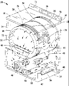
Figure 1 illustrates an exemplary clothes dryer appliance 10 in which
the herein described methods and apparatus may be practiced. While described
in the
context of a specific embodiment of dryer 10, it is recognized that the
benefits of the
-2-

09HLI9991
CA 02446359 2003-10-23
herein described methods and apparatus may accrue to other types and
embodiments
of dryer appliances. Therefore, the following description is set forth for
illustrative
purposes only, and the herein described methods and apparatus is not intended
to be
limited in practice to a specific embodiment of a dryer appliance, such as
dryer 10.
Clothes dryer I0 includes a cabinet or a main housing 12 including a
front panel 14, a rear panel 16, a pair of side panels 18 and 20 spaced apart
from each
other by front panel 14 and rear panel 16, a bottom panel 22, and a top cover
24.
Within cabinet 12 is a drum or container 26 mounted for rotation around a
substantially horizontal axis. A motor 44 rotates drum 26 about the horizontal
axis
through a pulley 43 and a belt 45. Drum 26 is generally cylindrical in shape,
having
an imperforate outer cylindrical wall 28 and a front flange or wall 30
defining an
opening 32 to drum 26 for loading and unloading of clothing articles and other
fabrics.
A plurality of tumbling ribs (not shown) are provided within drum 26
to lift clothing articles therein and then allow them to tumble back to the
bottom of
drum 26 as the drum rotates. Drum 26 includes a rear wall 34 rotatably
supported
within the main housing 12 by a suitable fixed bearing. Rear wall 34 includes
a
plurality of holes 36 that receive hot air that has been heated by an
electrical heater 40
in communication with an air supply duct 38 and duct inlet 42. The heated air
is
drawn from the drum 26 by a blower fan 48 which is driven by a blower motor
54.
The air passes through a screen filter 46 which traps any lint particles. As
the air
passes through the screen falter 46, it enters a trap duct seal and is passed
out of the
clothes dryer through an exhaust duct 50. After the clothing articles have
been dried,
they are removed from drum 26 via opening 32.
A cycle selector knob 70 is mounted on a cabinet backsplash 71 and is
in communication with a control system 56. Signals generated in control system
56
operate drum 26 and heating elements 40 in response to a position of selector
knob 70.
Blower motor 54 is a variable speed motor that is controlled by control system
56.
With reference to Figure 2, dryer 10 includes a temperature sensor 64
at drum hot air inlet 60 operable to produce a temperature signal indicative
of an inlet
air temperature. A second temperature sensor 68 is operable to produce a
temperature
signal indicative of a drum outlet temperature in outlet duct 50. A pressure
sensor 80
is operable to produce a pressure signal indicative of air pressure in outlet
duct 50.
-3-

09HL 19991
CA 02446359 2003-10-23
An inverter 66 regulates the frequency of the electric current supplied to
motor 54 to
control the operation of motor 54.
Figure 3 is a schematic block diagram of control system 56 including a
controller 90 which is in communication with temperature sensors 64 and 68 and
pressure sensor 80. Controller 90 also is in communication with drum motor 44,
inverter 66, and variable speed motor 54. Controller 90 is programmed to
perform
functions described herein, and as used herein, the term controller is not
limited to just
those integrated circuits referred to in the art as controllers, but broadly
refers to
microprocessors, computers, processors, microcontrollers, microcomputers,
programmable logic controllers, application specific integrated circuits,
field
programmable gate arrays, and other programmable circuits, and these terms axe
used
interchangeably herein.
In operation, a user selects a drying cycle through control system 56.
Controller 90 then controls motor 54 to vary the speed of blower fan 48.
Controller
90 contains multiple program algorithms associated with the drying options
available
to the user through control system 56. For example, in one drying cycle
controller 90
directs inverter 66, controlling the duty cycle of inverter 66, to maintain
blower fan 48
at a constant speed. For another drying cycle, controller 90 directs inverter
66 to vary
the speed of blower fan 48 based on temperature feedback from one or both of
temperature sensors 64 and 68. For another drying cycles controller 90 signals
inverter 66 to vary the speed of blower fan 48 based on pressure feedback from
pressure sensor 80.
In another embodiment, controller 90 directs inverter 66 to operate
motor 54 at a constant torque. In this mode, inverter 66 is similar to a
pressure sensor
in that inverter 66 automatically responds to varying pressures. Factors that
affect
pressure within duct 50 include lint buildup or a length of outlet duct 50,
including the
venting distance to the outside of the home for establishing an optimal drying
time. In
another drying cycle, an algorithm directs controller 90 to control motor 54
based on a
combination of temperature signals from drum inlet temperature sensor 64 and
drum
outlet temperature sensor 68 and pressure sensor 80 to vary airflow from
blower fam
48 to facilitate a reduction in drying time.
In another embodiment, controller 90 is programmed to determine a
ducting pressure loss based on the pressure signal from pressure sensor 80 and
regulate the operation of motor 54 based on the determined ducting pressure
loss. In
_4_

09HL 19991
CA 02446359 2003-10-23
one embodiment, controller 90 regulates the operation of motor 54 based on the
outlet
temperature of drum 26 to maintain a constant inlet air temperature setpoint
for drum
26. In yet another drying cycle, controller 90 is programmed to regulate the
operation
of motor 54 based on a signal indicative of clothes load (e.g. weight) in drum
26.
Optionally, motor 54 may be a self governing motor that varies speed
based on load such as a high slip induction motor. In this case, the dryer
would not
include an inverter.
From the preceding, it is shown that various methods are available to
control variable speed blower motor 54. In an exemplary embodiment, control
system
56 receives a signal from temperature sensor 68 and pressure sensor 80, and
control
system 56 controls the operation of blower motor 54 based on the received
pressure
and temperature signals. One method also includes controlling blower motor 54
based on the load size in drum 26. Load size can be selectively set by the
user or
automatically determined by measuring an increase of the weight of drum 26 due
to
the clothes load. One method also includes controlling blower motor 54 to
maintain a
constant inlet air setpoint for the dryer.
In describing one method in more detail, controller 90 executes one of
several algorithms stored therein to contxol blower motor 54 based on the
selection of
a drying cycle by the user of the dryer. Controller 90 controls the operation
of blower
motor 54 based on the received temperature and pressure signals and load size
indications. In one embodiment, inverter 66 is operatively coupled to blower
motor
54 wherein control of blower motor 54 is accomplished by controlling the duty
cycle
of inverter 66 based on temperature. In an exemplary embodiment, control
system 56
directs inverter 66 to control motor 54 at a constant torque and varies the
duty cycle to
inverter 66 based upon sensed temperature to adapt to different pressures for
different
ducting conditions while also controlling inverter 66 based on temperature.
The embodiments thus described provide a clothes dryer with a
variable speed blower motar that allows the dryer to be operated in a manner
that
facilitates improving dryer efficiency, reducing energy consumption, and
lowering
drying time which also facilitates extending the useful life of the dryer. In
varying the
blower speed, the capability is provided to compensate for such factors as
ducting
length and the number of bends, load size and lint filter conditions to
facilitate
delivering more heat to the clothes.
_5_

09HL19991
CA 02446359 2003-10-23
While the invention has been described in terms of various specific
embodiments, those skilled in the art will recognize that the invention can be
practiced
with modification within the spirit and scope of the claims.
_S_

Dessin représentatif
Une figure unique qui représente un dessin illustrant l'invention.
États administratifs

2024-08-01 : Dans le cadre de la transition vers les Brevets de nouvelle génération (BNG), la base de données sur les brevets canadiens (BDBC) contient désormais un Historique d'événement plus détaillé, qui reproduit le Journal des événements de notre nouvelle solution interne.

Veuillez noter que les événements débutant par « Inactive : » se réfèrent à des événements qui ne sont plus utilisés dans notre nouvelle solution interne.

Pour une meilleure compréhension de l'état de la demande ou brevet qui figure sur cette page, la rubrique Mise en garde , et les descriptions de Brevet , Historique d'événement , Taxes périodiques et Historique des paiements devraient être consultées.

Historique d'événement

Description Date
Inactive : CIB désactivée 2021-11-13
Inactive : CIB en 1re position 2021-05-31
Inactive : CIB attribuée 2021-05-31
Inactive : CIB expirée 2020-01-01
Le délai pour l'annulation est expiré 2017-10-23
Lettre envoyée 2016-10-24
Accordé par délivrance 2010-12-14
Inactive : Page couverture publiée 2010-12-13
Préoctroi 2010-09-24
Inactive : Taxe finale reçue 2010-09-24
Un avis d'acceptation est envoyé 2010-04-13
Lettre envoyée 2010-04-13
Inactive : Approuvée aux fins d'acceptation (AFA) 2010-03-31
Lettre envoyée 2008-10-30
Toutes les exigences pour l'examen - jugée conforme 2008-09-26
Modification reçue - modification volontaire 2008-09-26
Requête d'examen reçue 2008-09-26
Exigences pour une requête d'examen - jugée conforme 2008-09-26
Demande publiée (accessible au public) 2004-12-27
Inactive : Page couverture publiée 2004-12-26
Inactive : CIB attribuée 2003-12-22
Inactive : CIB en 1re position 2003-12-22
Lettre envoyée 2003-11-24
Inactive : Certificat de dépôt - Sans RE (Anglais) 2003-11-24
Demande reçue - nationale ordinaire 2003-11-24

Historique d'abandonnement

Il n'y a pas d'historique d'abandonnement

Taxes périodiques

Le dernier paiement a été reçu le 2010-09-24

Avis : Si le paiement en totalité n'a pas été reçu au plus tard à la date indiquée, une taxe supplémentaire peut être imposée, soit une des taxes suivantes :

  • taxe de rétablissement ;
  • taxe pour paiement en souffrance ; ou
  • taxe additionnelle pour le renversement d'une péremption réputée.

Les taxes sur les brevets sont ajustées au 1er janvier de chaque année. Les montants ci-dessus sont les montants actuels s'ils sont reçus au plus tard le 31 décembre de l'année en cours.
Veuillez vous référer à la page web des taxes sur les brevets de l'OPIC pour voir tous les montants actuels des taxes.

Historique des taxes

Type de taxes Anniversaire Échéance Date payée
Taxe pour le dépôt - générale 2003-10-23
Enregistrement d'un document 2003-10-23
TM (demande, 2e anniv.) - générale 02 2005-10-24 2005-09-22
TM (demande, 3e anniv.) - générale 03 2006-10-23 2006-09-22
TM (demande, 4e anniv.) - générale 04 2007-10-23 2007-09-28
TM (demande, 5e anniv.) - générale 05 2008-10-23 2008-09-26
Requête d'examen - générale 2008-09-26
TM (demande, 6e anniv.) - générale 06 2009-10-23 2009-09-22
Taxe finale - générale 2010-09-24
TM (demande, 7e anniv.) - générale 07 2010-10-25 2010-09-24
TM (brevet, 8e anniv.) - générale 2011-10-24 2011-09-27
TM (brevet, 9e anniv.) - générale 2012-10-23 2012-10-10
TM (brevet, 10e anniv.) - générale 2013-10-23 2013-09-25
TM (brevet, 11e anniv.) - générale 2014-10-23 2014-10-22
TM (brevet, 12e anniv.) - générale 2015-10-23 2015-09-22
Titulaires au dossier

Les titulaires actuels et antérieures au dossier sont affichés en ordre alphabétique.

Titulaires actuels au dossier
GENERAL ELECTRIC COMPANY
Titulaires antérieures au dossier
DOUGLAS ALLEN RIDDLE
EMILE EDWARD ABI-HABIB
JAMES ALAN MEYER
JEREMY MICHAEL GREEN
ZUBAIR HAMEED
Les propriétaires antérieurs qui ne figurent pas dans la liste des « Propriétaires au dossier » apparaîtront dans d'autres documents au dossier.
Documents

Pour visionner les fichiers sélectionnés, entrer le code reCAPTCHA :


Pour visualiser une image, cliquer sur un lien dans la colonne description du document. Pour télécharger l'image (les images), cliquer l'une ou plusieurs cases à cocher dans la première colonne et ensuite cliquer sur le bouton "Télécharger sélection en format PDF (archive Zip)" ou le bouton "Télécharger sélection (en un fichier PDF fusionné)".

Liste des documents de brevet publiés et non publiés sur la BDBC .

Si vous avez des difficultés à accéder au contenu, veuillez communiquer avec le Centre de services à la clientèle au 1-866-997-1936, ou envoyer un courriel au Centre de service à la clientèle de l'OPIC.


Description du
Document 
Date
(aaaa-mm-jj) 
Nombre de pages   Taille de l'image (Ko) 
Abrégé 2003-10-22 1 14
Description 2003-10-22 6 351
Revendications 2003-10-22 3 149
Dessins 2003-10-22 3 69
Dessin représentatif 2003-12-22 1 20
Dessin représentatif 2010-11-24 1 23
Courtoisie - Certificat d'enregistrement (document(s) connexe(s)) 2003-11-23 1 125
Certificat de dépôt (anglais) 2003-11-23 1 170
Rappel de taxe de maintien due 2005-06-26 1 109
Rappel - requête d'examen 2008-06-24 1 119
Accusé de réception de la requête d'examen 2008-10-29 1 190
Avis du commissaire - Demande jugée acceptable 2010-04-12 1 166
Avis concernant la taxe de maintien 2016-12-04 1 178
Correspondance 2010-09-23 1 37