Note : Les descriptions sont présentées dans la langue officielle dans laquelle elles ont été soumises.
CA 02448287 2003-11-20
WO 02/094348 PCT/AU02/00625
- 1 -
STAGED IL~LANTATIpN pF VEN2RTCASSIST ?DEVICES
The present invention relates to systems and devices
for the implantat~,on of ventricular assist. devices and,
more particularly, to such systems and devices su~.ted to a
staged regime.
B,ACKGfiOTIND
Blood ptxrnps are known for the purpose of assisting the
pumping function Qf a heaxt a.n a mammal.
1p In one partiGUlar form a class of pumps known as
"ventricular assist devices" assist, by pump~.nc~, the action
of the left ventricle of the heart.
Blood pumps suited for this task include those
disclosed in US6, 227, 797 (Watterspn et a~. ) and USS, 470, 20$
t5 (Kletschka}.
At the present time such pumps are relatively
expensive, partly due to current relatively low praduCtian
xuns and partly because of the relatively expensive
materials which must be utilized for the task of pumping
20 blood so as to maximize reliability c~f the pump and
minimize the possibility of blood damage.
It has been observed that, in same patients, the
"assi.st" funCtian provided by a ventricular assist device
permits the heart to recover function to the paint~where
CA 02448287 2003-11-20
WO 02/094348 PCT/AU02/00625
- 2 -
the ventricular assist device can be removed and the
patient's own heart takes over full pumping function.
Unfortunately, to date, no way has been found to
predict the likelihood of a temporary assist lead~inr~ to
satzsfactoxy or suffzci,ent recovery of heart pump function.
It is an object of the present invEntion, in at least
preferred embodiments, to provide a cost effective regime
for the use of blood pumps and which takes into account the
abavementioned problems.
1D
ENIEF L~ESt'~,IFTIaN OF INVENTION
FGaox.'da.ngl.y, in one broad f4rm of the invention there
is provided an implantation regime for a ventricular assist
device comprising:
~s (a) providing a first ventx~.cular assist device for
connection via a first ventricular assist device first
connector and a first ventricular assist device second
connector to a heart so as to assist heart function
for a first predetermined period a~ time;
z0 (b) providing a second ventricular assist device for
connection via a second ventricular ass~.st device
f~.xst connector and a second ventricular assist device
second connector to a heart. so as to assist heart
function for a second indeterminate period of time
CA 02448287 2003-11-20
WO 02/094348 PCT/AU02/00625
commencing immediately and contiguously following said
first predetermined period of t~.me.
Preferably said first ventricular assist dev~,oe is
adapted for short term use.
Preferably said first ventricular assist device is
adapted: for short term use comprising a period extending in
the range 0 to 6 months.
Preferably said fi.xst ventricular assist device is
adapted for short term use comprising a period extending in
the range 0 to 3 months.
Preferably said second ventriGUJ,ar assist device is
adapted for long term use.
Preferably sa~.d second ventricular assist devio~ is
adapted for long term use comprising a period of 1 to 20
x5 years.
Preferably sa~.d second ventricular assist device is
adapted for long term use Comprising a period of 1 to 10
years.
Preferably said first ventx~.cuJ.ar assist device is
made by a low cost process.
Tn a particular preferred form components of said
first ventricular assist device are made by an ~.njeotion
moulding p~roaess.
CA 02448287 2003-11-20
WO 02/094348 PCT/AU02/00625
- 4 -
In an alternative preferred foam components of said
first ventricular assist device are made by a vacuum
casting process.
Preferably said first v~1'itriCUlc'1r asSiSt deVlce
S includes a pump casing made from plastic components.
Preferably said first ventricular assist device
includes a pump rotor made from a plastic material.
Preferably said second ventricular assist dev~.ce
includes a pump casing made from a metallic material.
x0 Px~efe.rab~.y said second ven.txi.cuJ.ax assist device
includes a rotor made from a metallic material.
Preferably said second ventricular assist device
includes a pump casing made from a ceramic material.
Preferahly said second ventricular assist device
1,5 includes a rotor made from a ceramic material.
Tn an alternative particular farm said device
comprises a sac-type device.
Prefexablx said heart is connectable to said first
ventricular assist device by means of a respective first
'?0 cannula and second cannula interposed between said heart
and said first, connector and said heart and said second
connector respectively.
Preferably saa_d second ventricular assist device is
connectable to said heart via said first cannula and said
CA 02448287 2003-11-20
WO 02/094348 PCT/AU02/00625
- 5 -
second cannula by means of said second ventricular assist
device first connector and said second ventricular assist
device second connector respectively.
In a further broad form of the .invention there is
s provided a test procedure compri.s~.ng the connection of a
first ventricular assist device so as to assist a diseased
heart far a first predeterm~.ned period o~F t~.me: monitoring
operation of said heart over said predetermined period of
time so as to determine whether said heart can operate
without the further assistance of said first ventricular
assist device.
Preferably said first ventr~.cu~.ar assist device
incorporates short term life features {necessitated by
reduced cost of manufacturing) which render said first
1~ ventricular assist device suited to operation over a short
life span.
Preferably said short term life features ino~.ude use
of plastic materials in one or more of the pump casing a.nd
pump rotor of said first ventricular assist device.
Preferably said short life span comprises a period of
up to 6 manths.
Preferably said short life span aompx~.ses a per~.4d of
up to 3 months.
CA 02448287 2003-11-20
WO 02/094348 PCT/AU02/00625
- 6 -
In yet a further broad form of the invent~.pn there is
provided a method of mechanically assisting a heart to pump
blood; said method Coxnpri.sing releasably, sealingly
connecting via a first cannula and a second Canriula a first
ventricular assist device so as to at least assist said
heart to pump said blood; during a first predetermined
period of tzme, ascertaining if mechanical assistance
continues to be required and, if so, Subst~.tutang a second
ventr~.cuJ.ax ass~.st dev~.ce fear said first ventricular assist
1o device at the end of said first predetermined period of
time.
In yet a furthex broad form of the invention there is
provided, in Combination, a first ventricular. assist device
adapted for short term use and a second ventricular assist
device adapted far. J.onc~ term use.
In yet a further broad form of the invention there is
provided a first cannula having a proximal end for
connection to the aorta; a second can.nula having a proximal
end for connection to a ventricle; said first cannula
having a distal end including connection means for
releasably, sealingly Connecting said distal, end of said
fzxst Gannula to either an inlet of a first ventricular
assist device or an anlet of a second ventricular assist
device; a second cannula having a distal end including
CA 02448287 2003-11-20
WO 02/094348 PCT/AU02/00625
connection means for releasably, sealingly connecting said
distal end of said second cannuJ.a to either an outlet of
said .first ventricular assist device or an outlet of said
second ventricular assist device; said second ventricular
assist device adapted for subst,itutian for said fixst
ventricular assist device following a first predetermined
period of operation of said first ventricu~.ar assist
device.
In yet a further broad form of the invention there is
provided an embolisation device adapted for insCrtion into
ei.thex sa~,d fzxst cannu7.a ox said second cannula; said
embalisatian device including a stem having an end adapted
to deliver a coagulating material to a sealing position
within said proximal end of said first. cannula or said
second Cannula.
In yet a further broad form of the invention there i~
provided a pexcutaneaus lead for carriage of power to said
device; said lead having a surface; said surface including
regions which permit incorporation of the percutaneous lead
2o surface into the surrounding tissue and a region or regions
which will not allow incorporation. The region allowing
incorporation may extend the entire length of the
percutaneous lead or none of it or it may extend over
reg~,ons near the ventri,cu~.ar assist device sufficient only
CA 02448287 2003-11-20
PCTIAU02/00625
Received 26 August 2003
-S-
to help anchor the device in. place or near to the site
where the percutaneous lead exits the body and provide
good closuze to the sound so as to prevent or reduce the
occurrence of infection. In addition other areas on the
surface of the percutaneous lead may have properties
which prevent incorporation so as to facilitate easy
removal of the lead at the end of the predetermined
perj.od of Implantation of the first ventricular assist
device.
In yet a further broad form of the invcn~tion there
is provided a method of mechanically assisting a heart to
pump blood; said method comprising releasably, sealingly
connecting a first ventricular device via a first cannula
and a second cannula so as to at least assist said heart
to pump said blood during a first predetermined period of
time,, ascertaining .if mechanical assistance .continues to .
be required and, if so, substituting a second ventricular
assist device at the end of said first predeterarined
period of time and wherein first arid second ventricular
assist devices are ~mplantable into a patient's body and
are both pumping devices and wherein said first
ventricular assist device is adapted for short term use
and wherein said second ventricular assist device is
adapted for long term use.
AMEfvt.,,.-::: ~.;;~_'
IP~,~/~h
CA 02448287 2003-11-20
PCT/AU02J00625
Received 26 August 2003
-8A-
Preferably said cannular are capable of being reused
for connattion of said first ventricular assist device or
said second ventricular assist device.
Preferably said first ventricular assist device
incorporates short term life features which renders said
first ventricular assist device suited to operation over
a short life span.
Preferably said short term life features include use
of plastic material in one or more of the pump casing sad
pump rotor of said first ventricular assist device.
Preferably said cannulae are capable of being either
permanently or temporarily scaled so as to allow
permanent implantation of the cannulae without need to he
connected to either said first ventricular assist device
or said second ventricular assist device.
Preferably said_.first ..cannula includes an end for
connection to the aorta and a distal end connecting to
either an inlet of a first ventricular assist device or
an inlet of a second ventricular assist device, xn use;
and said second cannula includes an end for connection to
a ventricle and a distal end connecting to either an
outlet of said first ventricular assist device or an
outlet of said second ventricular assist device, in use.
AMi_I'y:.i; ~ _..1....
(Pt~~~
CA 02448287 2003-11-20
PCT/AU02100625
n~ceived 26 August 2003
-BH-
Preferably said second ventricular assist device is
adapted for substitution of said first ventricular assist
device following a first predetermined period of
operation of said first ventricular assist device.
Preferably the first cannula ox the second cannula
are adapted to receive the insertion of an embolisation
device.
Preferably said first ventricular assist device is
made by an injection moulding pxocess.
Preferably said first ventricular assist device is
made by a vacuum casting process.
Preferably said first ventricular assist device
includes a pump rotor made from a plastic material.
Preferably said second ventricular assist device
includes a pump casing made from a metallic material.
Preferably said, second ventricular assist device
includes a pump casing made from a ceramic material.
Preferably said second ventricular assist device
includes a rotor made from ceramic material
Preferably said short term use is a period of time
between 3 to 6 months.
Preferably said long term use is a period of time
between 7 to 1p years.
~h:~':~ .. . ..
Ipf_:,ir.~ ~
CA 02448287 2003-11-20
PCTlAU02/00625
Received 26 August 20x3
-8C
Preferably said method includes a test procedure to
determine whether heart can operate without the further
assistance of said first ventricular assist device.
Preferably said test procedure includes a monitozing
operation of said heart over said predetermined period of
t i~ne .
Preferably said method includes the use of an
insulated percutaneous lead for supplying power to either
a first or second ventricular assist device.
Preferably a portion of an outer surface of said
lead prevents incorporation of suzrounding tissue.
Preferably a portion of an outer surface of said
lead allows incorporation of surrounding tissue.
Preferably said surface comprises one surface
texture.
.Preferably said lead inc.~udes.at least two surface
textures on predetermined portions of the surface of said
lead, wherein a first surface texture allows
incorporation of said lead into tissue and whezein a
surface texture prevents incorporation of said lead into
tissue.
Preferably an amount of tissue incorporation of said
lead can be varied to suit needs by arrangement o~ the
surface textures.
AM~'ra~~h ~ '.:r,~::;
lFF.w'rtU
CA 02448287 2003-11-20
PCT/AU02/00625
Received 26 August 2003
-8D-
Preferably said surface textures comprises at least
one application of a surface treatment to said lead.
Preferably said surface texture is modified as to
the degree to which said incorporation of portions of
said lead into tissue surrounding said lead is promoted
therein,
Preferably said surface treatment includes an
application of velour to the surface of said lead.
Preferably said first surface texture has a
labyrinth arrangement.
Preferably said incorporation of portions of said
lead into tissue surrounding is promoted controlled by
selection of depth and shape of said surface textures.
Preferably the portion allowing incorporation may
extend to a length sufficient to anchor said lead to a
site.where said lead exits.the body.or proximal, to ,said . .
site.
Preferably the second surface texture prevents
incorporation so as to facilitate easy removal of the
lead.
Preferably said method includes an embolisation
device for insertably sealing a cannula, wherein said
embolisation dEvice comprises a scaling cap at a first
end, a carrier surface at a second end and an elongate
stem adapted to be inserted within the cannula.
iuli~:~~ii~~ ;_:-~4:_ ' . .
IF~J,;~
CA 02448287 2003-11-20
R~,Nroz~oob~S'
~oa~ad~-~
_s~_
Preferably the carrier surface is adapted to carry a
coagulating material.
Preferably said embolisation device seals a cannula
at a scaling point close to the heart.
Preferably said sealing cap is adapted to be
sealingly cannected to a corresponding connector on the
cannula.
Preferably the elongated stem is of a length so that
when the device is entirely inserted within said cannula,
the carrier surface is positioned to deliver coagulating
material to the sealing point.
Preferably said embolisation device is Connected
removably and releasably to the cannula, in use.
In yet a further broad form of the invention there
is provided an embolisation device for insertably sealing
a cannula. wherein said~embolisation device comprises a ~. ~ w
sealing Cap at a first end, a carrier surface at a second
end: wherein the carrier surface is adapted to carry a
coagulating material and induces an embolism at a
position proximal to said second end and an elongate stem
adapted to be inserted within the cannula.
Preferably said embolisation device seals a cannula
at a sealing point proximal to a heart of a patient, in
use.
r'~lrlei~i.W ~ .
IFi.;liu
CA 02448287 2003-11-20
PCT/AU02l00625
Received 26 August 2003
-8 F-
Preferably said scaling cap is adapted to be
sealingly connected to a corresponding connector of the
cannula.
Preferably the elongated stem is of a length so that
wheh the device is entirely inserted within said cannula,
the carrier surface is positioned to deliver coagulating
material to a sealing point at some point proximal to a
heart of a patient, in use.
Preferably said scaling point .is sufficiently close
to the heart so that there is no requirement to remove
the cannula from the body.
Preferably said embolisation device is connected
removably and releasably to the cannula, is uae.
sius~ Dssc~xr~rmrr og n~~s
One embodiment. of the present invention will now be
describEd with reference to the accompanying drawings
wherein:
Fig. 1 is a flow diagram illustrating steps in an
implantation regime in accordance with a first preferred
embodiment of the present invention.
Fig. 2 is a side section view of cannulae and an
embolisation tool in accordance with a particular
embodiment of the present invention.
AMENBVi;. v:! :."
ll~ChL4~
CA 02448287 2003-11-20
PCT/AU02/00625
Received 26 August 2003
-$G-
Fig. 3 is a cross-section through a patient's chest
and abdomen showing the ventricular assist device in
place and the path of the percutaneous lead from the exit
site in the skin to the ventricular assist device.
~r~~r~~~:~.: , y
nc;.~~:.
CA 02448287 2003-11-20
WO 02/094348 PCT/AU02/00625
DETAILED DE$CRIP'T=CiN OF PEEFERRED EL~ODtI~NT
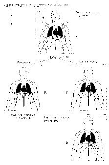
With reference to Fig. 1 comprising sub--diagrams 1A,
~F3, 1~ and 7.L~ there is illustrated steps in an implantation
regime 10 according to a first preferred embodiment o.L the
.5 present invent~.an.
In Fig. 1A a patient 11 having a heart 12 in need of
at least an assisted pumping action is fitted with a first
ventricular assist device 13 arranged, in this instance, to
provide a pumped blood flaw "in parallel" across left
ventricle 14 of heart 12.
In this instance the fluid connection is effected by
first cannula 15 and second cannula I~ as illustrated in
Fig. 1.
More particularly first cannula 15 sealingly connects
~s via first connector 17 to ventricular assist device 13
whilst second cannula 16 sealingly connects to ventricular
assist device 13 by way of second connector 18.
Tn this instance the length of cannulae 15, ~.~ is such
as to permit first ventricular assist device l~ to be
z0 placed in the abdomen 19 of patient 1X.
As will be discussed furthEr below the intention is
that first ventricular assist devioe 13 is to be utilized
for a relatively short predetermined period of time,
typically up to approximately 3 . to 6 months. ~ ThiS
CA 02448287 2003-11-20
WO 02/094348 PCT/AU02/00625
- 10 -
predetermined period of time will be sufficient to monitor
the function of heart ~.2 so as to determine whether the
assistance provided by first ventricular assist device ~.3
is sufficient to allow fu~.~. or suk~stantial recovery of
s heart 12 to the point where no ventricular assist device is
required.
In this event, as sha~rn in Fig. 1B, at the end of the
predetermined period of time 20 the first ventricular
assist device 13 is removed fram the abdomen 19 and first
connector 17 and second connector 18 sealed.
In a particularly preferred form, as illustrated in
Fig. 2, cannul~.e 15, 16 are. sealed internally at a poa.nt
sufficiently close to the heart 12 that there is no need to
xemove Gannu~.ae ~.5, x6 at the tame that first ventricular
assist device 13 is removed.
Sealing can be effected by use of a first embolisation
tool 21 and a second embolisation tool 22 fax respective
first cannula 15 and second cannula 16.
Each teal 21, 22 comprises an elongate stem 23, 24
respectively having sealing caps 17A, 18A respectively at a
first end {refer Fig. 2) and a carrier surface 25, 26 at
respective secand ends.
The carrier surfaces 25, 26 are adapted to carry a
coagulating material 27. The sealing caps-X7A. ~.8A are
CA 02448287 2003-11-20
WO 02/094348 PCT/AU02/00625
- 11 -
adapted to be sealingly connected to first connector 17 and
second connector 38 respectively upon insert~.on of the
entire length of stems 23, 24 into cannulae 15, 16.
The length of stems 23, 24 is selected so that when
,5 tools 2I, 22 are entirely inserted within cannulae 15, 16
the carrier surfaces 25, 26 are positioned so as to deliver
coagulating material 27 to sealing positions 28, 29 which
are sufficiently close to the heart 12 that, upon sealing
of cannulae 15, 16 at positions 28, 2g them is no
requirement to xemove cannulae 15, 16 from the body.
Typically it will be clear within a predetermined
period of between one and three months of use of first
ventricular assist device J.3 as to whether sufficient
recovery of hca.rt 12 will be made that the option of
x'emoval of first ventricular assist device 13 a.nd
appropriate sea~.zng or removal of cannulae 15, 16 can take
place as outlined in step H of Fig. 1.
Once the predetermined period 20 has expired and it is
budged that heart 12 is unlikely to recover th.es, as per
steps C and D in Fig. 1 first ventricular assist device 1~
is removed az~d a.mmediate~.y rep~.aced with second ventricular
assist device 30.
'The replacement is performed by disconnecting first
connector 31 of first VAD 13 from first connector 17 0~
CA 02448287 2003-11-20
WO 02/094348 PCT/AU02/00625
- 1Z -
first aannula 15 and disconnecting second connector 33 of
first VAD 13 from first connector 18 of second cannu~a I6,
withdrawing first ventricular assist device 13 from abdomen
19 and immediately substituting there~_n second ventricular
assist device 30 and then connecting first connector 32~of
second ventricular assist device 30 to fzxst cannula 15 and
second connector 34 of second ventricular assist, device 30
to second cannula 16 by way of respective first connections
17, 18 of cannulae 15, 16.
Ideally, immediately prior to disconnection of first
ventricular device 13, cannulae 15,16 are clamped so no air
can enter or blood .leak out. The clamps are maintained
while seGOnd ventriGUlar assi$t device 30 is connected to
the same cannulae. The clamps are removed once connection
IS is completed.
With reference to Fig. 3 there is illustrated an
exemplary ~rentricular assist device 13, 30 having
respective first connectors 31, 32 and respective secotxd
connectors 33, 34 zor the passage of bland through the
device.
The ventricular assist device 13, 30 requires power
which is conducted through percutaneous lead 40 from
outside of the body via exit site 44.
CA 02448287 2003-11-20
WO 02/094348 PCT/AU02/00625
- 13 -
Ta facilitate the removal of the percuta.neous lead 40
which carries electrical energy and epntrol to the
ventricular assist device 13 (and subsequently second
ventricular assist device 30), the outer surface of the
percutaneous lead 40 may be treated so as to prevent the
incorporation into surrounding tissue 41 of the
percutaneous lead 4d. Such surface treatment may extend
the eiltire length of ,the percutaneous lead 40, or may be
terminated ju$t below the suxfaoe 4~ of the skin 42 sa as
1U to allow full incorporation at the exit site 44 and hence a
barrier to infection. An example of surface treatment of
the percutaneous lead 40 is the use of silicone rubber
which naturally resifts incorporation. Tncorparation at or
near the exit site 44 may be achieved through the use of
t5 adhesively bonded woven velour 45 ar other material or
surface treatment which will provide tissue ingrowth ~.s the
outermost surface of the percutaneous lead in this region.
A~.texnat~.veJ.y the surface treatment can comprise texturing
of surface 46 of lead 40.
~n As shown in inset X in fig. ~ the texturing of surface
46 of lead 40 can be such that ingrowth of tissue 41 can be
only mildly anchored, for example by the use of a pyxam~,d-
shaped texture whereby there is little anchoring of !:issue
to. surface 46. Alternatively the texturing 'can include a
CA 02448287 2003-11-20
WO 02/094348 PCT/AU02/00625
_ 1~ _
labyrinth arrangement such as illustrated in inset 2 of
Fig. 3 wherein tissue 41 can follow a labyrinth path
through the intex~stzCes 4$ of J.abyrznth texture 47.
As previously stated the texture can extend the entire
length of lead 4p within the body from the exit $ite 44
through to device 13, 30. In the alternative the texturing
may be at selected and predetermined locations.
The texturing itself can be tailored whereby the
degree of tissue ingrowth into the surface 46 is controlled
70 and tailored as a function of displacement along the
surface of lead 40.
The surface can be tailored to provide a high degree
of ingrowth such as that provided by inset 2 or can be
tailored to provide only minimal ingrowth as, for example,
75 provided in inset 1.
zt is to be noted that, because of the location of
both first ventricular assist device 13 and second
ventricular assist dev~.ce 30 in abdomen 1~, pex~mztted by
appropriate selection of cannulae 15, 16 it follows that
'20 the substitution of second ventricular assist device 30 for
faxst ve~ntxicu~.ar assist device 13 may take place without
patient ventilation or formal heart bypass during the
procedure because there is np need to open the Chest cavity
of patient 11. This arrangement thereby may significantly
CA 02448287 2003-11-20
WO 02/094348 PCT/AU02/00625
- 15 -
limit risk to the patient as compared with the situation
where general anaesthesia or heart bypass is required.
Second ventricular assist device 30 is intended for
long term operation which is to say for many years, ideally
extending to beyond the expected lifetime of patient l1.
Tn particular both first ventricular assist device 13
and second ventricular assist device 30 will, ideally,
share the same surgically created packet in abdomen 19.
Broadly, it will be appreciated that first ventricular
1U assist device 13 is zz~tended far short term use and thereby
can have its characteristics selected for short term 'use
whil$t second ventricular assist device 30 is intended for
long term use and therefore can have its Characteristics
selected for long term use.
~y way of example first ventricular assist device 13
can take the form of almost any la~,aod pump including those
disclosed in US&,227,797 (Watterson et al) and US5,470,208
(F~Ietschka) p~'ovided only that the l~laod pump is sized to
fit in the pocket created in abdomen 19. In particular the
?0 fzrst ventricular assist device 13 may comprise an axial or
centrifugal pump, or sac~type device. Its impeller may be
suspended in any number of ways including mechanically,
magnetically and hydxodynamically or by a combination of
these. In the case of a saG-type ~d:e~-ic~e urging of the
CA 02448287 2003-11-20
WO 02/094348 PCT/AU02/00625
1~
blood through the devioe may be caused by the reciprocating
action of a pusher-plate or similar mechan~.sm in a sac-type
devi ce .
Its components can be made using mass production
techniques and utilising less expensive materials than far
the long life second ventr~.culax assist device.
In particular the components comprising the pump
casing and intexna~. surfaces and rotating parts can be made
from plastic materials including polymeric materials.
i0 Coatings (such coatings not necessarily having a
significantly long life) can be applied so as to increase
blood compatibility. It is noted that same plastic
materials such as Covalently bonded heparin are
particularly suited to receive anal support such coatings.
The Carmeda process can be utilized to perform the covalent
banding pf Heparin. In addition or alternatively the
coating may constitute a slow-release antibiotic.
In a further particular form the first ventricular
assist device 13 adapted for sho-r-t term use need not be
hermetically sealed. Instead it may con2.prise one or mare
components in respect pf which slow permeation of body
fluids is acceptable. Examples of slaw permeat~.on
materials which may be suitable include polypropylene,
epoxy or nylon.
CA 02448287 2003-11-20
WO 02/094348 PCT/AU02/00625
- 17 -
Conversely, second ventricular assist device 3d is
constructed for long term (which is to say much greater
than 3 months and typically, of the order of many years)
reliable operation and can embody, for example, the
principles of rotor support described in US6,227,797
(Watterson et al) and US5,470,20$ (Kletschka). In this
znstance, suztable mater9.als from which to construct the
pump casing and/or the pump rotor for reliable, long term
operation zna~.ude hermetically welded titan~.um alloy.
to The above describes only some embodiments of the
present invention and modifications, obvious to those
ski~.J.ed ~.n the art can be made thereto without depa~rt~,ng
from the scope and spirit of the present invention.