Note : Les descriptions sont présentées dans la langue officielle dans laquelle elles ont été soumises.
CA 02450060 2003-11-18
CYCLONE VACUUM CLEANER
BACKGROUND OF THE INVENTION
1. Field of the invention
The present invention relates generally to a cyclone vacuum cleaner, and more
particularly, to a cyclone vacuum cleaner of which an operation handle can be
directly
connected to assorted accessory brushes.
2. Description of the Related Art
A cyclone is an apparatus for separating particles in a fluid using
centrifugal
force. The cyclone has been widely used in industrial fields as a dust
collector due to its
simple structure and durability against heat and pressure. The cyclone is also
used in
vacuum cleaners.
A vacuum cleaner having a dust collector, as shown in Fig. 1, reduces the
amount of dust being collected in a paper filter which is disposed in a main
body 30, by
gathering relatively large dust which is entrained in air drawn into a cyclone
dust
collector 20. Therefore, the paper filter disposed in main body 30 can be used
for longer
periods without requiring cleaning or replacement. In addition, the vacuum
cleaner
1
CA 02450060 2003-11-18
having the cyclone dust collector 20 enables effective cleaning while
simultaneously
inhibiting overload on a motor.
A vacuum cleaner having the cyclone dust collector 20 draws in air, including
entrained dust and dirt, through a brush 10 and extension pipe 11 of the
vacuum cleaner
to an essentially cylindrical main body 21 of the cyclone dust collector 20.
The air
stream enters the cylindrical body 21 an oblique or tangential direction.
Accordingly, an
air whirlpool or cyclone is generated, and thereby the various dust and dirt
entrained in
the air are separated by centrifugal force of the cyclone, and axe collected
in a dust
receptacle 22. Air from which dust is removed reverses direction of travel
from the
bottom of the dust receptacle 22 rotating within a smaller radius and
gradually rising
toward a central portion at the top of the cyclone dust collector 20, and then
is discharged
to the main body 30 through an operation handle 23 and a flexible hose
assembly 24.
However, it is inconvenient to use a conventional vacuum cleaner having the
cyclone dust collector 20 between the extension pipe 11 and the operation
handle 23,
since an accessory brush (not shown), such as a crevice tool or a dusting
accessory, is
connected directly to the operation handle 23, and therefore, the area to be
cleaned is
obstructed by the dust collector 20. Moreover, an extension pipe with a
predetermined
length is needed to connect the accessory brush (not shown) to the operation
handle 23.
2
CA 02450060 2003-11-18
SUMMARY OF THE INVENTION
It is an object of the present invention to provide an improved cyclone vacuum
cleaner in order to removably connect an accessory brush directly to an
operation handle.
In order to achieve the above-described objects of the present invention,
there is
provided a cyclone vacuum cleaner comprising a main body, a flexible hose
assembly
extending from the main body, an operation handle, wherein one end is
connected to the
flexible hose assembly and the other end is connected to an extension pipe for
use with
a brush which is in contact with an area to be cleaned, a cyclone dust
collector for
collecting dust disposed between the main body and the operation handle, and a
brush to
draw in the dust on the area to be cleaned being connected to the operation
handle.
According to a first preferred embodiment of the invention, it is preferable
that
the cyclone dust collector is disposed between the operation handle and the
flexible
hose assembly.
In addition, according to a second preferred embodiment of the invention, the
flexible hose assembly comprises a first flexible hose to be connected to the
operation
handle and a second flexible hose to be connected to the main body. The
cyclone dust
collector is disposed between the first and second flexible hoses.
The cyclone dust collector may further comprise a cyclone body for generating
3
y , CA 02450060 2003-11-18
an air whirlpool current with respect to air flowing into the cyclone body,
which has an
air inlet leading to the operation handle, and an air outlet in fluid
communication with
the main body, a dust receptacle removably connected to the cyclone body by a
locking
unit, a first upstream prevention member integrally formed with the dust
receptacle, a
dust separation grill which is extending downwardly from the air outlet in the
cyclone
body and having a plurality of fine holes in a surface thereof, and a second
upstream
prevention member formed at the lower part of the dust separation grill
removed from
the air outlet.
The locking unit may further comprise a hinge projection formed on the
operation handle and a hinge hole formed in the dust receptacle corresponding
to the
hinge projection.
A connecting end of the dust receptacle, corresponding to a virtual arc of an
imaginary circle, having a locus on the hinge projection, the virtual arc on
the plane is
disposed in a direction perpendicular to a shaft of the hinge projection.
In addition, a cyclone vacuum cleaner according to a third preferred
embodiment may comprise a main body, a flexible hose assembly at one end
connected
to and extending from the main body, an operation handle one end of which is
connected to another end of the flexible hose assembly, and the other end of
the
4
< CA 02450060 2003-11-18
operation handle is connected to an extension pipe to be joined with a brush
which will
be contacted with an area to be cleaned, a cyclone dust collector which is
connected to
the flexible hose assembly, and the other end is connected to the main body,
and a brush
for drawing in dust on the area to be cleaned.
The cyclone dust collector may comprise a cyclone body for generating an air
whirlpool current with respect to air flowing into the cyclone body, which has
an air
inlet providing fluid communication to the flexible hose assembly, and an air
outlet
providing fluid communication to the main body, a dust receptacle removably
connected
with the cyclone body by a locking unit, a first upstream prevention member
integrally
formed with the dust receptacle, a dust separation grill extending downwardly
from the
air outlet in the cyclone body with a plurality of fine holes formed on a
surface thereof,
and a second upstream prevention member formed at the lower part of the dust
separation grill removed from the air outlet.
Further, in a cyclone vacuum cleaner according to a fourth preferred
embodiment, the air inlet of the cyclone dust collector is oriented in a
coaxial direction
relative to the air outlet.
Further, in a cyclone vacuum cleaner according to the fifth preferred
embodiment, the air inlet of the cyclone dust collector is oriented in a non-
coaxial
CA 02450060 2003-11-18
direction relative to the air outlet.
If the air inlet of the cyclone dust collector is in a non-coaxial orientation
relative
to the air outlet, it is preferable that the air path of the cyclone dust
collector is skewed.
BRIEF DESCRIPTION OF THE DRAWING FIGURES
These and other features, aspects, and advantages of the present invention
will
become better understood with regard to the following description, appended
claims,
and accompanying drawings where:
Fig. 1 is a perspective view of a vacuum cleaner having a conventional cyclone
dust collector;
Fig. 2 is a side view of a cyclone dust collector disposed between an
operation
handle and a flexible hose assembly, according to the first preferred
embodiment of the
present invention.
Fig. 3 is a partially cut-away plan view showing a structure of a dust
receptacle
of the cyclone dust collector of Fig. 2.
Fig. 4 is a side view of the cyclone dust collector shown disposed in the
middle
of the flexible hose assembly, according to a second preferred embodiment of
the
present invention.
6
CA 02450060 2003-11-18
Fig. 5 is a perspective view of a vacuum cleaner with the cyclone dust
collector
disposed between the main body and the flexible hose assembly, according to a
third
preferred embodiment of the present invention.
Fig. 6 is a side view of the main body of a vacuum cleaner according to a
fourth
preferred embodiment of the present invention.
Fig. 7 is a side view of the main body of a vacuum cleaner according to a
fifth
preferred embodiment of the present invention.
DETAILED DESCRIPTION OF THE PREFERRED EMBODIMENTS
Hereinafter, preferred embodiments of a cyclone vacuum cleaner according to
the present invention will be described in detail with reference to the
accompanying
drawings.
Figs. 2 through 4 show a cyclone dust collector disposed between an operation
handle and a flexible hose assembly. Portions having the same objective and
structure
and identifying essentially identical elements as the prior art will be
referred to by the
same reference numerals.
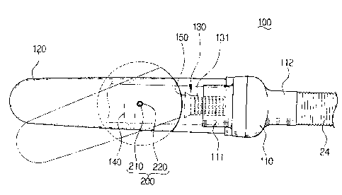
Figs. 2 and 3 illustrate a first preferred embodiment of the present
invention.
A cyclone dust collector 100 comprises a cyclone body 110, a dust receptacle
7
CA 02450060 2003-11-18
120, a dust separation grill 130, and first and second upstream prevention
members 140,
150, respectively.
The cyclone body 110 forms an air whirlpool current with respect to air
flowing
into the body 110. It comprises an air inlet 111 fluidly communicating with
the
operation handle 23, and an air outlet 112 fluidly communicating with the main
body 30
through a flexible hose assembly 24.
The dust receptacle 120 is removably connected to the cyclone body 110 by a
locking unit 200. The locking unit 200 will be described in detail below.
The first upstream prevention member 140 is integrally formed with the dust
receptacle 120 and provides a primary means for preventing dust collected in
the
cyclone body 110 from flowing into the main body 30.
The dust separation grill 130 extends downwardly nn a direction away from the
air outlet of the cyclone body 110, and has a plurality of fine holes 131
formed in a
surface thereof.
The second upstream prevention member 150 is formed at the lower part of the
dust separation grill 130, removed from the connection of the grill 130 to the
cyclone
body 110, and provides for providing secondary dust filtering, i.e., for
separating dust
which has not been filtered by the first upstream prevention member 140.
8
CA 02450060 2003-11-18
The cyclone dust collector 100 having the above structure is connected on one
end of its structure to the operation handle 23 providing the air inlet 111,
and at the
other end is connected to the flexible hose assembly 24, providing the air
outlet 112.
On the other hand, since the cyclone dust collector 100 is disposed between
the
operation handle 23 and the flexible hose assembly 24, the dust receptacle 120
may
become obstructed by the operation handle 23 when separating the two.
Therefore, the
dust receptacle 120 is removably connected with the cyclone body 110 by the
locking
unit 200 so as to provide a structure not obstructed by the operation handle
23.
The locking unit 200 comprises a hinge projection 210 extending from the
operation handle 23, and a hinge hole 220 formed in the dust receptacle 120
corresponding to the hinge projection 210 for cooperation therewith.
It is preferable that the hinge projection 210 extends from the lower surface
of
the operation handle 23. However, the hinge projection 210 can be formed on
the side
surface of the operation handle 23, if necessary or desired.
A connecting end of the dust receptacle 120 may be formed in the shape of an
arc following an imaginary circle having a center or locus at the hinge
projection 210,
when viewed from above, as shown in Fig. 3.
It is preferable that the dust separation grill 130 does not exceed in length
beyond
9
CA 02450060 2003-11-18
the connecting end, so that the rotation of the dust receptacle 120 is not
obstructed.
Fig. 4 illustrates in a side view a second embodiment of the present
invention,
wherein the cyclone dust collector 100 is disposed in the middle of the
flexible hose
assembly 24 between two separated sections of hose. Again, like or similar
elements
are identified by identical reference numerals.
In this embodiment, the flexible hose assembly 24 is comprised of a first
flexible hose 24a, one end of which is connected to the operation handle 23,
and a
second flexible hose 24b, one end of which is connected to the main body 30 of
the
cleaner. The cyclone dust collector 100 is disposed between the first and
second
flexible hoses 24a, 24b.
Therefore, it is possible to removably connect the dust receptacle 120 to the
cyclone body 110 by means of the locking unit 200, which is comprised of the
hinge
projection 210 and the hinge hole 220. However, other appropriate connection
means,
such as a rotation connection system, which is the subject an application by
the present
applicant, disclosed in Korean Patent 2001-0046138 may also be used.
Fig. 5 illustrates a third preferred embodiment of the present invention,
wherein
the cyclone dust collector 100 is directly connected to the main body 30 of
the cleaner.
In this embodiment, one end of the cyclone dust collector 100, which is the
air inlet, is
CA 02450060 2003-11-18
connected to the distal end of flexible hose assembly 24 furthest from the
operation
handle 23, and the other end, which is the air outlet, is connected to the
main body 30.
Since the cyclone dust collector 110 is fixed directly to the: main body 30 in
this case,
cleaning work becomes easier since the combination of the cyclone dust
collector 100
and main body 30 move together as one structure.
Figs. 6 and 7 show a fourth and the fifth embodiments of the present
invention,
respectively.
As shown in Figs. 6 and 7, a cyclone dust collector 300 comprises a cyclone
body 310 and a dust receptacle 320. The cyclone dust collector 300 comprises
an air
inlet 311 connected to the flexible hose assembly 24, and an air outlet 312
connected to
a suction port 31 of the main body 30. The dust receptacle; 320 collects dust
separated
by an air whirlpool current, and is removably connected to the cyclone body
310, which
itself is disposed above the main body 30.
In the cyclone body 310, as in Fig. 6, the air inlet 311 can be disposed in a
coaxial orientation relative to the air outlet 312. The air inlet 311 can also
be disposed in
a non-coaxial orientation relative to the air outlet 312, as shown in Fig. 7.
Hereinafter, the operation of the cyclone vacuum cleaner according to the
present invention will be described with reference to the accompanying
drawings.
11
CA 02450060 2003-11-18
Suction force is generated by a suction motor as power is applied, and then
air,
including entrained dust, is drawn into the cyclone dust collector 100 through
a brush 10,
which draws in dust located on an area to be cleaned, and then through an
operation
handle 23. Then, the air is directed to the air inlet 111 of the cyclone body
110, which
creates a downwardly directed whirlpool current guided by an air path forming
body.
As the centrifugal rotation force of the air whirlpool current increases, even
fine
dust entrained in the air can be separated from the rotating air whirlpool
current. The
separated dust descends along the inside wall of the cyclone body 110 and is
collected
in the bottom of the dust receptacle 120.
The downwardly directed air whirlpool current, from which dust is now removed,
reverses direction from the bottom of the cyclone body 110, and forms an
ascending
current rotating with a smaller radius within the outer, downwardly directed
air current.
Here, if the rotation force of the air whirlpool current increases,
turbulence, which is
normally generated in the bottom of the cyclone body 110 as the air current
reverses
direction, can be reduced. Accordingly, an air whirlpool current can be
generated which
can separate dust from the air more effectively. The ascending current passes
through
the dust separation grill 130, and then flows through the flexible hose
assembly 24 into a
dust collecting chamber (not shown) located in the main body 30 (Fig. 1).
12
CA 02450060 2003-11-18
Meanwhile, dust which is collected in the dust receptacle 120 may also ascend
together with the ascending current. However, relatively large particles of
dust cannot
pass through the holes 131 of the dust separation grill 130, and the large
dust particles
drop to the bottom of the dust receptacle 120.
The remaining procedures at the dust collecting chamber in the main body 30
are performed in a conventional manner as those of a general vacuum cleaner,
and are
not further described herein.
When cleaning narrow spaces, accessory brushes 4U, such as a crevice tool, can
be directly connected to the operation handle 23 instead of being connected to
an end of
an extension pipe 11.
According to the preferred embodiment of the present invention, accessory
brushes can be directly connected to the operation handle. 23, and therefore,
inconvenience resulting from having to carry a heavy extension pipe can be
reduced.
While the invention has been shown and described with reference to certain
preferred embodiments thereof, it will be understood by those skilled in the
art that
various changes in form and details may be made therein without departing from
the
spirit and scope of the invention as defined by the appended claims.
13