Sélection de la langue

Search

Sommaire du brevet 2450536 

Énoncé de désistement de responsabilité concernant l'information provenant de tiers

Une partie des informations de ce site Web a été fournie par des sources externes. Le gouvernement du Canada n'assume aucune responsabilité concernant la précision, l'actualité ou la fiabilité des informations fournies par les sources externes. Les utilisateurs qui désirent employer cette information devraient consulter directement la source des informations. Le contenu fourni par les sources externes n'est pas assujetti aux exigences sur les langues officielles, la protection des renseignements personnels et l'accessibilité.

Disponibilité de l'Abrégé et des Revendications

L'apparition de différences dans le texte et l'image des Revendications et de l'Abrégé dépend du moment auquel le document est publié. Les textes des Revendications et de l'Abrégé sont affichés :

  • lorsque la demande peut être examinée par le public;
  • lorsque le brevet est émis (délivrance).
(12) Brevet: (11) CA 2450536
(54) Titre français: CONNECTEUR D'EXTREMITE POUR CHENILLE DE TRACTEUR
(54) Titre anglais: END CONNECTOR FOR CATERPILLAR TRACKS
Statut: Périmé et au-delà du délai pour l’annulation
Données bibliographiques
(51) Classification internationale des brevets (CIB):
  • B62D 55/21 (2006.01)
(72) Inventeurs :
  • SPIES, KLAUS (Allemagne)
  • STEINEBRUNNER, NORBERT (Allemagne)
  • NEUBERT, BERND-DIETER (Allemagne)
(73) Titulaires :
  • DST DEFENCE SERVICE TRACKS GMBH
(71) Demandeurs :
  • DST DEFENCE SERVICE TRACKS GMBH (Allemagne)
(74) Agent: SMART & BIGGAR LP
(74) Co-agent:
(45) Délivré: 2010-04-27
(86) Date de dépôt PCT: 2002-06-15
(87) Mise à la disponibilité du public: 2003-01-03
Requête d'examen: 2006-04-25
Licence disponible: S.O.
Cédé au domaine public: S.O.
(25) Langue des documents déposés: Anglais

Traité de coopération en matière de brevets (PCT): Oui
(86) Numéro de la demande PCT: PCT/EP2002/006624
(87) Numéro de publication internationale PCT: WO 2003000536
(85) Entrée nationale: 2003-12-12

(30) Données de priorité de la demande:
Numéro de la demande Pays / territoire Date
101 30 385.8 (Allemagne) 2001-06-23

Abrégés

Abrégé français

Avec des raccords terminaux étroits (13), une erreur de manipulation sur la vis de serrage (30) risque d'entraîner une rupture de chaîne par le glissement des raccords terminaux (13). Ce risque est éliminé par des tiges transversales (7) placées en biais et situées sur l'extérieur de la vis de serrage (30).


Abrégé anglais


In the case of narrow end connectors 13 due to handling errors at
the clamping screw 30 there is the risk of the track coming apart due to
end connectors 13 slipping off. That is prevented by inclinedly inserted
transverse pin members 7. They bear at the outside against the clamping
screw 30.

Revendications

Note : Les revendications sont présentées dans la langue officielle dans laquelle elles ont été soumises.


6
CLAIMS:
1. An end connector for caterpillar tracks in which
track link bodies are provided with rubber-mounted pins, and
end connectors connect the pins of adjacent track
link bodies,
the width of the end connectors approximately
corresponds to the diameter of the pins,
wherein each end connector is in the form of a
closed elastic clip with two eyes and a slot connecting the
eyes, and
has a clamping means which is disposed at a right
angle with respect to the slot,
wherein transverse pin members are fixed in the
pins,
the transverse pin members lie in the slot and
form an abutment for the clamping means in the
sense of a connection securing means,
wherein
the transverse pin members bear tangentially
against the outside of the clamping means and are disposed
inclinedly to the pin axis,
such that the transverse pin members lie within
the contour of the connector which is of an only slightly
greater width than the diameter of the clamping means.
2. An end connector according to claim 1 wherein the
clamping means is a screw.

Description

Note : Les descriptions sont présentées dans la langue officielle dans laquelle elles ont été soumises.

CA 02450536 2008-07-18
26793-95
1
End connector for caterpillar tracks
The invention concerns end connectors for caterpillar tracks.
DE 34 05 699 C2 discloses end connectors for caterpillar tracks, in
which track link bodies are provided with rubber-mounted pins. The pins of
adjacent track link bodies are connected together by the end connectors.
The end connectors are in the form of closed elastic clips having two eyes
for the pins and a slot which connects the eyes. The pins are to be screwed
fast in the eyes of the end connectors by way of a clamping means such as
a screw. The rubber mountings for the pins are pre-stressed. The pre-
stressing of that rubber mounting arrangement is established by means of
transverse pin members which are fixed in the pins and which engage into
the slot. The transverse pin members are displaced laterally with respect to
the screw, more specifically being arranged at the outside.
It has been found in practice that the screw prestressing force is
reduced when handling errors occur. The risk of a track coming apart due
lu eiid connectors slipping off is great, particularly in the case of
caterpillar
tracks with only two end connectors on the track width. In order to prevent
the end connectors from slipping off, the transverse pin members engage
behind the screw in the region of the outside surface of the connectors.
In the case of end connectors of small width, the transverse pin
members cannot serve as a means for preventing the connectors from
slipping off as, for reasons of space, they cannot be arranged beside the
screw.
An aspect of the invention is to secure very narrow end connectors
to prevent them from slipping off the pins when there are handling errors
at the screw. The width of the connectors approximately corresponds to the
diameter of the pins.

CA 02450536 2009-08-10
26793-95
2
The invention relates to an end connector for
caterpillar tracks in which track link bodies are provided
with rubber-mounted pins, and end connectors connect the
pins of adjacent track link bodies, the width of the end
connectors approximately corresponds to the diameter of the
pins, wherein each end connector is in the form of a closed
elastic clip with two eyes and a slot connecting the eyes,
and has a clamping means which is disposed at a right angle
with respect to the slot, wherein transverse pin members are
fixed in the pins, the transverse pin members lie in the
slot and form an abutment for the clamping means in the
sense of a connection securing means, wherein the transverse
pin members bear tangentially against the outside of the
clamping means and are disposed inclinedly to the pin axis,
such that the transverse pin members lie within the contour
of the connector which is of an only slightly greater width
than the diameter of the clamping means.
Embodiments of the invention are illustrated in
the drawing in which:
Figure 1 is a partial view in section of a
connector and a two-pivot pin track shown in simplified
form,
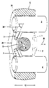
Figure 2 shows an end connector with inclinedly
inserted transverse pin members in the pins,
Figure 3 shows an elastic stirrup with transverse
pin members which are integrally connected thereto,

CA 02450536 2008-07-18
26793-95
2a
Figures 4 - 7 show stirrup securing arrangements,
Figures 8 - 10 show shoe securing arrangements,
Figure 11 shows a stirrup securing arrangement, and
Figure 12 shows a steel cable or steel plate securing arrangement.
Referring to Figure 1, arranged in track link members 1 and 2 of a
two-pivot pin track are pins 3 and 4 with known rubber bearings 5 and 6.
The pins 3 and 4 of circular cross-sections are provided at their ends with
transverse pin members 7. The pin members 7 are fitted in force-locking
engagement in bores 8 in the pins 3 and 4.
io A connector 13 is of a symmetrical configuration with respect to the
axis 20. It has two eyes 21 which are connected by a slot 24 of a width 25.
Provided on the axis 20 is a screwthread connection in the form of a screw
30, a bore 32 and a screwthreaded bore 33.
The transverse pin members 7 project into the slot 24, with a slight
amount of lateral clearance. As shown in Figure 2 those transverse pin
members 7 are fixed inclinedly in the pins 3, 4 and are disposed between
the screw 30 and the outside surface 34 of the connector 13.
Upon assembly of the connector 13, the pins 3 and 4, which are
provided with the transverse pin members 7, of the track link bodies 1 and
Zo 2 are seif-adjustingly oriented in relation to the bearing eyes 21 and the
slot 24.

CA 02450536 2003-12-12
3
The rubber bearings 5 and 6 fix the pins 3 and 4 with the transverse
pin members 7 in the track link bodies 1 and 2 in the illustrated position,
corresponding to an assembly angle 14. That assembly angle 14 is a
measurement in respect of the prestressing of the rubber bearing
arrangements (not shown) in the track link bodies 1 and 2.
As shown in Figure 2, the transverse pin members 7 are inserted
inclinedly, from the ends of the pins 3, 4, more specifically at an angle 38
of 75 .
The connector 13 is pushed on to the pins 3, 4 in the direction
indicated by the arrow 39. The screw 30 which is thereafter fitted in place
fixes the pins 3, 4 in the connector 13 in force-locking or frictional
engagement. The force-locking engagement is so designed that no relative
movement of the pins 3, 4 takes place in the connector 13. The function of
the transverse pin members 7 is to ensure the correct assembly position of
the pins 3, 4 in the connector in accordance with the angle 14 and, in the
event of handling errors in relation to the screw 30 or in the event of the
screw 30 not being sufficiently tightened, to prevent the connector 13 from
slipping off the pins 3, 4, in the opposite direction to the arrow 39. The
transverse pin members 7 bear tangentially against the outside 9 of the
screw 30.
The connector 13 is of an only slightly greater width 12 than the
diameter 11 of the screw shank 10 of the screw 30. The arrangement
therefore has only a small amount of usable space for the means according
to the invention for preventing it from slipping off.
As shown in Figure 3, provided on a stirrup 40 which is of an
approximately right-angled configuration are transverse pin members 41
which are formed in one piece thereon.
The stirrup is fitted prior to insertion of the screw 30, by a procedure
whereby the stirrup 40 is compressed until the transverse pin members 41
can be pressed into the bores 8. After insertion of the screw the stirrup 40
bears in a prestressed condition against the screw 30 in the region 42.

CA 02450536 2003-12-12
4
As shown in Figure 4 a stirrup 44 embraces approximately half the
periphery of the screw 30 and engages with hook-shaped projections 46
behind the transverse pin members 48.
A variant in that respect can be seen in Figure 5, wherein the hook-
shaped projections 50 of a stirrup 51 form a V-shape 52.
Stirrups 54, 56 with counterclockwise eyes 55, Figure 6, and
clockwise eyes 57, Figure 7, secure the connectors 13. The eyes 55 bear at
the track link body side against the transverse pin members, see Figure 6,
and, as shown in Figure 7, both against the transverse pin members 7 and
also against the screw 30.
An elastic shoe securing arrangement 60 can be seen in Figure 8.
Two shoes 62 are connected by way of an external elastic band portion 64.
The shoes 62 each have an inclined run-on surface 66 and an opening 68
for receiving the transverse pin members 7. The shoe securing
arrangement 60 comprises steel. For the assembly procedure, the shoe
securing arrangement 60 is inserted into the slot 24 of the connector 13
and fitted into the end position illustrated, by being pressed into place. In
that procedure, the inclined run-on surface 66 slides with the flat portion
69 on the transverse pin member 7. An abutment 70 secures the shoe
securing arrangement 60 after it has been fitted on by resilient
deformation. Both the shoe 62 and also the band portion 64 extend around
the screw 30.
As shown in Figure 9 there are two individual shoes 74 to provide the
securing action. The shoe securing arrangements 74 accommodate the
transverse pin member 7 in an opening 76 and bear with an arcuate
configuration 78 against the screw 30.
Figure 10 shows a rigid shoe securing arrangement 80. Provided in
an approximately square body 82 are a bore 84 for mounting the screw 30
and openings 85 for receiving the transverse pin members 7.
As shown in Figure 11 an elastic stirrup 86 of steel with receiving
bores 88 for the transverse pin members 7 is fitted in place.
What is common to the above-described securing arrangements is
that, when the structure does not involve a fixed fit of the connector 13 on

CA 02450536 2003-12-12
the pins 3 and 4, the loose connector 13 is held or bears against the
described securing arrangements.
Another structure corresponding to Figure 12 provides a securing
action in the same manner, in which the screws 30 of the connectors 13
5 which are disposed at both sides of the track link bodies 1, 2 on the pins 3
and 4 are connected by a steel cable 90. Suitable loops 92 extend around
the screws 30. As an alternative thereto, a further structure involves a
sheet metal plate or bar 94 with corresponding eyes 96.

Dessin représentatif
Une figure unique qui représente un dessin illustrant l'invention.
États administratifs

2024-08-01 : Dans le cadre de la transition vers les Brevets de nouvelle génération (BNG), la base de données sur les brevets canadiens (BDBC) contient désormais un Historique d'événement plus détaillé, qui reproduit le Journal des événements de notre nouvelle solution interne.

Veuillez noter que les événements débutant par « Inactive : » se réfèrent à des événements qui ne sont plus utilisés dans notre nouvelle solution interne.

Pour une meilleure compréhension de l'état de la demande ou brevet qui figure sur cette page, la rubrique Mise en garde , et les descriptions de Brevet , Historique d'événement , Taxes périodiques et Historique des paiements devraient être consultées.

Historique d'événement

Description Date
Le délai pour l'annulation est expiré 2019-06-17
Lettre envoyée 2018-06-15
Lettre envoyée 2016-03-16
Accordé par délivrance 2010-04-27
Inactive : Page couverture publiée 2010-04-26
Préoctroi 2010-02-10
Inactive : Taxe finale reçue 2010-02-10
Un avis d'acceptation est envoyé 2010-01-25
Lettre envoyée 2010-01-25
Un avis d'acceptation est envoyé 2010-01-25
Inactive : Approuvée aux fins d'acceptation (AFA) 2010-01-21
Modification reçue - modification volontaire 2009-08-10
Inactive : Dem. de l'examinateur par.30(2) Règles 2009-02-09
Modification reçue - modification volontaire 2008-07-18
Inactive : Dem. de l'examinateur par.30(2) Règles 2008-01-31
Lettre envoyée 2007-12-28
Exigences de rétablissement - réputé conforme pour tous les motifs d'abandon 2007-12-14
Réputée abandonnée - omission de répondre à un avis sur les taxes pour le maintien en état 2007-06-15
Lettre envoyée 2006-05-16
Toutes les exigences pour l'examen - jugée conforme 2006-04-25
Exigences pour une requête d'examen - jugée conforme 2006-04-25
Requête d'examen reçue 2006-04-25
Inactive : IPRP reçu 2004-05-12
Lettre envoyée 2004-03-05
Inactive : Page couverture publiée 2004-02-18
Inactive : Notice - Entrée phase nat. - Pas de RE 2004-02-13
Inactive : Transfert individuel 2004-01-30
Demande reçue - PCT 2004-01-12
Exigences pour l'entrée dans la phase nationale - jugée conforme 2003-12-12
Demande publiée (accessible au public) 2003-01-03

Historique d'abandonnement

Date d'abandonnement Raison Date de rétablissement
2007-06-15

Taxes périodiques

Le dernier paiement a été reçu le 2010-04-06

Avis : Si le paiement en totalité n'a pas été reçu au plus tard à la date indiquée, une taxe supplémentaire peut être imposée, soit une des taxes suivantes :

  • taxe de rétablissement ;
  • taxe pour paiement en souffrance ; ou
  • taxe additionnelle pour le renversement d'une péremption réputée.

Veuillez vous référer à la page web des taxes sur les brevets de l'OPIC pour voir tous les montants actuels des taxes.

Titulaires au dossier

Les titulaires actuels et antérieures au dossier sont affichés en ordre alphabétique.

Titulaires actuels au dossier
DST DEFENCE SERVICE TRACKS GMBH
Titulaires antérieures au dossier
BERND-DIETER NEUBERT
KLAUS SPIES
NORBERT STEINEBRUNNER
Les propriétaires antérieurs qui ne figurent pas dans la liste des « Propriétaires au dossier » apparaîtront dans d'autres documents au dossier.
Documents

Pour visionner les fichiers sélectionnés, entrer le code reCAPTCHA :


Pour visualiser une image, cliquer sur un lien dans la colonne description du document. Pour télécharger l'image (les images), cliquer l'une ou plusieurs cases à cocher dans la première colonne et ensuite cliquer sur le bouton "Télécharger sélection en format PDF (archive Zip)" ou le bouton "Télécharger sélection (en un fichier PDF fusionné)".

Liste des documents de brevet publiés et non publiés sur la BDBC .

Si vous avez des difficultés à accéder au contenu, veuillez communiquer avec le Centre de services à la clientèle au 1-866-997-1936, ou envoyer un courriel au Centre de service à la clientèle de l'OPIC.


Description du
Document 
Date
(aaaa-mm-jj) 
Nombre de pages   Taille de l'image (Ko) 
Abrégé 2003-12-12 1 8
Description 2003-12-12 5 193
Revendications 2003-12-12 3 81
Dessins 2003-12-12 12 201
Dessin représentatif 2003-12-12 1 14
Page couverture 2004-02-18 1 34
Description 2008-07-18 6 207
Revendications 2008-07-18 3 70
Description 2009-08-10 6 203
Revendications 2009-08-10 1 28
Abrégé 2010-01-25 1 8
Dessin représentatif 2010-04-06 1 8
Page couverture 2010-04-06 1 34
Rappel de taxe de maintien due 2004-02-17 1 107
Avis d'entree dans la phase nationale 2004-02-13 1 190
Courtoisie - Certificat d'enregistrement (document(s) connexe(s)) 2004-03-05 1 105
Accusé de réception de la requête d'examen 2006-05-16 1 190
Courtoisie - Lettre d'abandon (taxe de maintien en état) 2007-08-13 1 174
Avis de retablissement 2007-12-28 1 166
Avis du commissaire - Demande jugée acceptable 2010-01-25 1 163
Avis concernant la taxe de maintien 2018-07-27 1 180
PCT 2003-12-12 14 550
PCT 2003-12-13 7 282
Taxes 2007-12-14 2 61
Correspondance 2010-02-10 1 41