Note : Les descriptions sont présentées dans la langue officielle dans laquelle elles ont été soumises.
CA 02450676 2003-09-08
WO 02/072264 PCT/US02/07113
METHOD AND SYSTEM FOR MICROFLUIDIC INTERFACING TO ARRAYS
BACKGROUND OF THE INVENTION
Field of the Invention
The present invention relates generally to the field of devices for performing
detection
reactions involving biomolecules. In particular, the invention relates to
devices for
processing microarray slides used in such detection reactions. More
specifically, the
invention relates to a novel device for interfacing with a microarray slide to
provide for the
controlled delivery of fluids to selected regions of the slide surface as well
as an instrument
for performing simultaneous processing of a plurality of microarray slides,
each used in
combination with an interface device according to the invention.
Description of Related Art
A variety of biological and chemical assays have been developed for detecting
the
presence of compounds of interest in samples. In the biomedical field, methods
for detecting
the presence of specific nucleotide sequences, proteins or peptides are
utilized, for example,
in diagnosing various medical conditions, determining predisposition of
patients to diseases,
and performing DNA fingerprinting.
In general, biological and chemical assays are based on exposing an unknown
sample
to one or more known reactants and monitoring the progress or measuring the
outcome of the
reaction. It is often desirable to expose a sample to multiple reactants, to
react multiple
dilutions of a single sample with one or multiple reactants, to expose
multiple samples to a
single reactant, or to perform multiple repetitions of a particular assay for
a given sample, in
order to improve reliability. There is currently a high level of interest in
the development of
high throughput methods for performing multiple biological and chemical
analyses of this
type simultaneously, quickly, and conveniently.
One recently developed method for performing multiple chemical reactions
simultaneously is to form a microarray of multiple spots of reactant molecules
on a planar
substrate such as a glass microscope slide, typically in a two-dimensional
grid pattern, and
apply liquid reagents and reactants to the slide to contact multiple spots
simultaneously.
Various reaction steps may be perfonned with the bound molecules in the
microarray,
including exposure of bound reactant molecules to liquid reagents or
reactants, washing, and
incubation steps. The progress or outcome of the reaction (or other
association between
bound molecules and reagents which is not truly a reaction) may be monitored
at each spot in
1
CA 02450676 2003-09-08
WO 02/072264 PCT/US02/07113
the microarray in order to characterize either material(s) immobilized on the
slide or
material(s) in a liquid sample. Although it is typical to immobilize known
reactants on the
substrate and expose an unknown liquid sample (e.g., a "probe solution") to
the immobilized
reactants and monitor the reaction between the sample and the various
reactants in order to
characterize the sample, it is also possible to immobilize one or more unknown
samples on
the substrate and expose them to a liquid containing one or more known
reactants.
Microarrays are frequently used in analysis of DNA samples, but may also be
used in
diagnostic testing of other types of patient samples. Spots in microarrays may
be formed of
various large biomolecules, such as DNA, RNA, and proteins, smaller molecules
such as
drugs, co-factors, signaling molecules, peptides or oligonucleotides. Cultured
cells may also
be grown onto microarrays. As an example, if it is desired to detect the
presence of particular
DNA sequences in a patient sample, the sample is exposed to a microarray of
spots formed of
oligonucleotides having sequences complementary to sequences of interest. If
the DNA
sequence of interest is present in a patient sample, it will hybridize with
the bound
oligonucleotides. The occurrence of hybridization at a particular spot then
indicates the
presence of the sequence associated with that spot in the sample.
Hybridization can be
detected by various methods, many of which give indication of the quantity, as
well as
presence, of sequences of interest in the sample. One commonly used method
involves
labeling the sample with a fluorescent dye so that fluorescence can be
detected at spots where
hybridization occurred. Various types of slide readers are commercially
available for reading
microarray slides.
Microarrays offer great potential for performing complex analyses of samples
by
carrying out multiple detection reactions simultaneously. However, a current
limitation of
microarrays is the time and care required to process slides to obtain reliably
high quality
results. The need for high quality processing is particularly pronounced
because individual
microarrays slides are expensive and only limited quantities of the samples
used in the
reactions may be available, making it particularly important to obtain good
results
consistently.
Both manual and automated methods of processing microarrays have been
developed.
However, to date, no method has been completely satisfactory. In order to
process a
microarray manually, at certain reaction steps the appropriate reagent or
reactant solution is
applied to the microarray slide and a cover slip applied to spread the
solution out into a thin
layer that covers the entire microarray and prevents evaporation. Washing
steps are typically
carried out by placing slides in jars of wash solution. Each processing step
must be carried
2
CA 02450676 2009-07-13
WO 02/072264 PCT/US02/07113
out by hand, necessitating a large amount of human effort. Moreover, the
success of the
procedure is largely dependent on the skill of the human technician. A single
technician is
typically able to process at most only 10-15 slides per day. An additional
drawback of
manual processing techniques is that an essentially open system is used,
presenting a high
potential for evaporation, spilling or leakage of samples or reagents. If
microarray slides are
allowed to dry out, data quality will be compromised. Leakage and spilling can
be a
significant problem, in that certain samples or reagents may be hazardous, and
also because
leakage or spilling of genetic material, even in minute aniounts, can
contanlinate other
samples being processed in the lab and lead to erroneous results.
Various methods have been developed to overcome the limitations of manual
slide
processing. These range from simple slide processing chambers designed to
simplify the
application of solutions to microarray slides and reduce evaporation and
leakage of solutions,
to large and expensive machines capable of processing large numbers of slides
simultaneously.
Loeffler et al. (PCT publication WO 00/63670, dated 10/26/00) describe a slide
processing chamber designed for processing microarray slides. Freeman (U.S.
Patent
5,958,760, issued 9/28/99), Stapleton et al. (U.S. Patent 5,922,604 issued
7/13/99), Stevens et
al. (U.S. Patent 5,605,813, issued 2/25/97) and Richardson (U.S. Patent
6,052,,224, issued
4/18/00) all disclose slide processing chambers not specifically disclosed for
use in
microarray processing, but which serve to illustrate the general state of the
art relating to the
processing of individual slides.
Devices capable of processing multiple slides simultaneously in an automated
fashion
are described by Custance (U.S. Patent 6,238,910, issued 5/29/01) and Juncosa
et al. (U.S.
Patent 6,225,109, issued May 1, 2001).
llevices for automated processing of microarray slides offer many advantages,
but are
prohibitively expensive for labs that do not need to process large numbers of
slides. In
addition, even with improved reproducibility delivered by automation, the
results obtained
with commercially available instruments of this type frequently do not meet
the high quality
and consisteney standards that are desirable, particularly because of the cost
of microarray
slides and the often limited availability of samples.
With increased interest and development effort in the field of microarrays,
equipment
used to manufacture microarrays on slides has been developed which allows for
the
3
CA 02450676 2003-09-08
WO 02/072264 PCT/US02/07113
formation of arrays with higher spot densities and smaller individual spot
sizes. At the same
time, detection equipment used with microarrays is becoming capable of
detecting smaller
spots at higher densities. However, some tests are best performed with a
number of spots less
than the total number that can be formed on a slide. It would be desirable to
exploit the
higher spot density and higher density detection capability by performing
several such tests
simultaneously on a single slide, essentially breaking one large high density
array into a
number of smaller arrays. It would thus be advantageous to have a method of
interfacing to a
microarray which would permit selective access to portions of a microarray.
There remains a need for a method of interfacing to microarray slides which
eliminates or minimizes leakage or spillage, provides reliable, reproducible
results, requires
minimal volumes of samples and reagents, and can be used conveniently for
manual
processing of small numbers of slides but may also be adapted to automated
slide processing
for handling larger numbers of slides.
SUMMARY OF THE INVENTION
The present invention is a system for processing microarray slides that is
made up of a
microarray interface device and an instrument capable of holding a plurality
of microarray
slides, interfacing with the microarray slides via their associated interface
devices, and
controlling various reaction conditions during processing of the microarray
slides. The novel
microarray interface device can be connected to a substrate bearing a
microarray of spots
made up of DNA, RNA, oligonucleotides, proteins, or other biomolecules. In
particular, the
array interface device is adapted for interfacing with glass microscope slides
and similar
planar substrates. The interface device provides for the delivery of sample,
reagents, rinses,
and so forth, to selected portions of the array in a controlled manner. In an
alternative
embodiment of the invention, the selective access to the array substrate
provided by the
interface device may be used in the formation of the spot microarray on the
substrate.
Although the device has been designed particularly for interfacing with slides
bearing
microarrays, the device may also be used to provide a fluid interface to
slides bearing various
other types of samples, and the application of the device is not limited to
use with microarray
slides.
The interface device seals against the surface of the microarray substrate. A
sealing
layer or gasket positioned between the interface device and substrate provides
a uniform,
non-leaking seal between the interface device and substrate. A clamp mechanism
may be
used to secure the interface device and substrate together. Indentations or
grooves in surface
4
CA 02450676 2003-09-08
WO 02/072264 PCT/US02/07113
of the interface device are aligned with spots in the microarray, so that when
the interface
device is sealed to the microarray substrate, the indentations or grooves form
one or more
reaction chambers, chambers or channels containing spots in the microarray.
Alternatively,
interface channels, chambers, or wells may simply be defined by openings in a
sealing or
gasket layer. Interface channels, chambers, or wells may access individual
spots, groupings
of spots, e.g. rows or blocks of spots within the array, or all spots in the
array. Size and
configuration of interface channels or wells are selected to provide uniform
filling with
minimal bubble formation. Interface channel volumes are kept low to reduce the
amounts of
sample and reagents that must be used.
The interface device includes one or more inlets and one or more outlets,
which
communicate with the interface channels, chambers or wells and which allow
fluids to flow
into and out of the interface channels, chanibers or wells to contact the
spots contained
therein. The invention may be provided with inlet and outlets suitable for
manual
introduction and removal of fluids via pipette or syringe, for example, or
automated
introduction and removal of fluids from the device via tubing connected to a
device such as a
pump device.
The interface device may include pre-array fluidic circuitry between the
inlets to the
interface device and the interface channels, chan-ibers, or wells, and post-
array circuitry
between the outlets of the interface channels, chambers or wells and the
outlets of the
interface device. Microfluidic circuitry may also be provided in series
between several
interface channels, chambers, or wells. Fluidic circuitry may include various
microfluidic
circuit elements, such as valves, reservoirs, structures for mixing or
dividing fluid streams,
stop junctions, air inlets, and air vents, which may be used to perform
various fluid control,
handling or processing steps with liquid reagents or reactants. Alternatively,
or in addition,
pre- or post-array processing may be provided in one or more separate modules
connected to
the interface device. Reactants may be present in the microfluidic circuitry
within the
interface device or in pre-processing or post-processing modules so that
reaction or
processing steps may be performed in these structures as well as on the
microarray slide
itself. As an example, the array interface and pre- or post-processing modules
may be
configured to perform labeling, pre-hybridization, and hybridization steps
used in the
processing of microarray slides.
The interface device has the capability to collect and store waste fluids
subsequent to
their passing through the device. In a preferred embodiment of the device,
waste fluids are
contained in a disposable portion of the interface device.
5
CA 02450676 2003-09-08
WO 02/072264 PCT/US02/07113
The interface device may include electrodes or other sensors for monitoring
the
movement of fluids within the system and the progress of reactions occurring
therein.
Electrodes may also be included within the device for producing electrokinetic
movement of
molecules in solution within the device. Heating elements or mixing mechanisms
may be
included in some embodiments of the interface device.
The interface device may be constructed by microfabrication or other
techniques
similar to those used in the integrated circuit and microelectromechanical
systems (MEMS)
and microfluidic systems industries, which are effective for fabricating
micrometer sized
structures for manipulating small volumes of fluids.
In a preferred embodiment of the invention, the interface device and slide are
placed
in a base that supports and stabilizes the slide and interface device,
controls various
parameters of slide processing, and may perform a number of auxiliary
functions. In the
most preferred embodiment of the invention, the base is a part of an
instrument that may
handle the processing of multiple slides simultaneously. The mechanism for
clamping
together the slide and the interface device may be incorporated into the base.
The base may
include a humidity chamber that surrounds the exterior of the seal between the
slide and
interface device. Heating or cooling elements may be provided in the base or
in the
instrument to allow reactions to be carried out at various temperatures. The
base or
instrument may include a mechanism for mixing or agitating of fluids within
the interface
channels and possibly other portions of the interface device to enhance
chemical reactions.
In certain embodiments of the invention, the instrument is capable of
receiving and securing
multiple slides for simultaneous processing in an automated slide processing
system. The
instrument may include a microprocessor, memory, and other electronics for
controlling
heating, cooling, mixing, and other functions carried out by the inventive
device. In certain
embodiments of the invention, the base is formed separately from an external
control module
that controls heating or mixing functions performed by the base.
It is an object of the invention to provide controlled delivery of fluids to
one or more
selected regions of a microarray slide. This is accomplished by appropriate
choice of size
and shape of interface channels or wells. By delivering fluids selectively to
several different
regions of the microarray, it is possible for multiple reactions to be carried
out
simultaneously, for parallel processing of multiple different samples or
multiple repetitions of
a single sample.
It is an object of the invention to provide a method and system for processing
microarray slides using very small volumes of samples and reagents at all
processing steps.
6
CA 02450676 2003-09-08
WO 02/072264 PCT/US02/07113
This is achieved by including microfluidic pre- and post-processing circuitry
in the interface
device and attached modules to allow all processing steps to be performed with
microvolumes of fluids. Minimal use of reagents and sample is cost effective
and makes the
system useful in cases where limited amounts of sample are available.
It is a further object of the invention to provide a method and system for
processing
microarrays which provides mixing of fluids on the microarray surface, while
at the same
time requiring only small volumes of sample and reagents. This is accomplished
by using a
reaction chamber having flexible wall portions that are moved by a novel
pneumatic mixing
system.
It is an object of the invention to provide a device for filling an interface
chamber on a
microarray slide evenly and without bubble formation. This is accomplished by
appropriate
selection of chamber size and configuration. Even, bubble-free filling results
in more
controlled delivery of reactants and reagents to the microarray and
consequently better results
from the processed microarray.
It is an object of the invention to provide an interface device that seals
reversibly to a
microarray slide without leaking or sample loss. Reversible, leak-free sealing
is obtained
tllrough the use of appropriately selected gasket or 0-ring material between
the interface
device and slide. A good seal provides for more successful processing of the
microarray and
minimizes problems associated with contamination of lab space by leaked
reagents and
reactants.
It is an object of the invention to provide a microarray interface device for
interfacing
with microarray slides that allows for performance of pre- and post-processing
steps. This is
accomplished by providing microfluidic circuitry in the interface device, and,
depending on
the processing steps required, additional pre- or post processing modules
attached in fluid
communication with the interface device. By providing for all stages of
processing to be
performed with the use of the inventive interface device, convenience and
efficiency of slide
processing is greatly enhanced.
It is an object of the invention to provide for the capture and containment of
waste
fluids resulting from microarray processing. This is achieved by providing a
waste reservoir
within the interface device connected to the outlet(s) of the interface
channels or wells. By
storing waste in the interface device, the collection and disposal of waste is
greatly simplified
and the safety and convenience of microarray processing is improved.
It is an object of the invention to provide a system for performing manual
processing
of individual microarray slides in a reliable and reproducible fashion. This
is accomplished
7
CA 02450676 2003-09-08
WO 02/072264 PCT/US02/07113
through the use of an interface device that receives manually delivered
reagents and reactants
and provides them to the surface of a microarray slide in a controlled manner.
It is an object of the invention to provide a system for processing multiple
microarray
slides simultaneously in an automated fashion. This object is achieved by
multiplexing the
microarray slide processing system to accommodate a desired number of slides.
BRIEF DESCRIPTION OF THE DRAWINGS
FIG. 1 is a perspective view of an exemplary embodiment of a slide processing
device
manufactured according to the invention;
FIG. 2 is a perspective view of a microarray slide/interface device
combination;
FIG. 3 is a cross-sectional view of the microarray slide/interface device
combination of FIG.
2;
FIG. 4 is a perspective view of a microarray of spots formed on a planar
substrate and an
embodiment of an interface device constructed according to the present
invention;
FIG. 5 is a perspective view of the interface device and microarray substrate
of FIG. 4 sealed
together;
FIG. 6 is a top view of the microarray substrate and interface device as shown
in FIG. 5;
FIG. 7 depicts an alternative method of forming inlets and outlets in an
interface device;
FIG. 8 depicts another alternative method of forming inlets and outlets in an
interface device;
FIG. 9 is a top view of an embodiment of the interface device, showing the
microarray,
including pre- and post-array microfluidics;
FIG. 10 is a perspective view of a three-dimensional interface device sealed
to a microarray
substrate;
FIG. 11 illustrates a method of clamping the interface device to a microarray
substrate;
FIG. 12 illustrates an alternative method of clamping an interface device to a
microarray
substrate;
FIG. 13 is an exploded view of a further exemplary embodiment of the interface
device;
FIG. 14 is a top view of the microfluidic circuitry layer of the embodiment of
the invention in
FIG. 13;
FIG. 15 is a cross sectional view of the microfluidic circuitry layer taken
along section line
15-15 in FIG. 14;
FIG. 16 is a bottom view of the microfluidic circuitry layer of the embodiment
of the
invention in FIG. 13;
FIG. 17 is a top view of the UO layer of the embodiment of the invention in
FIG. 13;
FIG. 18 is a cross sectional view of the I/O layer taken along section line 18-
18 in FIG. 17;
8
CA 02450676 2003-09-08
WO 02/072264 PCT/US02/07113
FIG. 19 is a schematic diagram of the microfluidic circuitry of the embodiment
of the
invention depicted in FIG. 13;
FIG. 20 is a top view of the assembled UO layer, microfluidic circuitry layer,
and microarray
slide;
FIG. 21 is a cross sectional view taken along section line 21-21 in FIG. 20;
FIG. 22 is a cross sectional view taken along section line 22-22 in FIG. 20;
FIG. 23 is an exploded view of another embodiment of the interface device
showing
alternative clamping and fluid inlet designs;
FIG. 24 is an assembled view of the device of FIG. 20;
FIG. 25 depicts an interface channel configuration for accessing an entire
microarray on a
microarray slide;
FIG. 26 is a cross section of an interface channel designed to reduce
formation of bubbles
during fluid introduction;
FIG. 27 depicts an interface channel configuration for accessing multiple
microarrays on a
microarray slide;
FIG. 28 depicts a system for mixing fluid on the microarray, within the array
interface;
FIG. 29A shows a first step of a microfluidic fluid circulation process;
FIG. 29B shows a second step of a microfluidic fluid circulation process;
FIG. 29C shows a third step of a microfluidic fluid circulation process;
FIG. 29D shows a fourth step of a microfluidic fluid circulation process;
FIG. 29E shows a fifth step of a microfluidic fluid circulation process;
FIG. 29F shows a sixth step of a microfluidic fluid circulation process;
FIG. 29G shows a seventh step of a microfluidic fluid circulation process;
FIG. 30 is a exploded perspective view of an alternative embodiment of the
invention;
FIG. 31 is an exploded perspective view of an alternative embodiment of the
invention;
FIG. 32 is a top view of the assembled device of FIG. 31;
FIG. 33 is a cross sectional view of an interface channel containing a liquid
filler;
FIG. 34 is a cross sectional view of an interface channel containing a
solidified filler;
FIG. 35 is a block diagram of an instrument for controlling processing of a
microarray slide;
FIG. 36 is a perspective view of an external control module connected to
multiple bases;
FIG. 37 is a perspective view of an adapter for delivering samples from a
multipipettor to
multiple interface devices;
FIG. 38 is a perspective view of an instrument including an adapter for
delivery of samples
from a multipipettor to multiple interface devices;
9
CA 02450676 2003-09-08
WO 02/072264 PCT/US02/07113
FIG. 39. is a perspective view of an instrument including a manifold for
delivering a single
sample to multiple interface devices; and
FIG. 40 is a schematic diagram of the microfluidic circuitry of FIG. 39.
DETAILED DESCRIPTION OF THE INVENTION
FIG. 1 depicts an example of a presently preferred embodiment of the
invention. The
invention includes an instrument 600, which includes multiple bays 602, each
of which is
adapted to receive a reaction device 604, which is made up of a microarray
slide in
combination with a microarray interface device. Bays 602 are located in base
603 on heat
block 606, which fits into well 608 in instnunent 600. Base 603 is formed as a
part of heat
block 606, or is formed separately and mounted on heat block 606. In either
case, base 603
and bays 602 are in thermal communication with heat block 606. Reaction
devices 604 are
heated by heat block 606 during microarray processing. Each reaction device
604 mates with
air connectors 609 and 610, visible in the empty bay 602. Air line connectors
609 and 610
are connected to a pressure source in instrument 600, which is used to drive
mixing of fluid in
reaction device 604. In the embodiment of the invention depicted in FIG. 1,
sample, reagent,
and wash liquids are introduced into each reaction device via inlet hole 612,
while air or
liquid exits reaction device via outlet hole 614. Inlet hole 612 and outlet
hole 614 are formed
in interface device 616 and are in fluid communication with a reaction chamber
on the
surface of the microarray slide. Control panel 618 allows the user to control
the various
functions performed by instrument 600, e.g. heat block temperature and mixing
parameters.
In this particular example, instrument 600 is made up of a commercial
laboratory heater 620
of the type used for heating test tubes, Eppendorf tubes, and the like, and a
pump unit 621, so
that the pump unit 621 and heat block 606 portion of the device can be
manufactured
separately from laboratory heater 620. Pump unit 621 pumps air alternately
into and out of
air line connectors 609 and 610 of each reaction device 604 via manifold 622.
The same
functions could be provided by an instrument in which pump and heating units
were built in
the same instrument case. Instrument 600 may include an opaque lid 624 to keep
the
microarray slides from being exposed to light, since light may bleach out dyes
commonly
used during microarray processing. Lid 624 may also provide thermal
insulation.
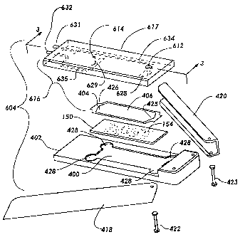
FIG. 2 is an exploded view of reaction device 604. As described in connection
with
FIG. 1, reaction device 604 includes interface device 616 sealed to microarray
slide 150. In
this case, interface device 616 is made up of main interface layer 617 and
gasket 404. A
reaction chaniber is formed between the upper surface of slide 150 and the
lower surface of
CA 02450676 2003-09-24
WO 02/072264 PCT/US0 2/117 1 1 3
main interface layer 617, the boundaries of the reaction chamber being defined
by opening
406 in gasket 404. Fluids are injected into the reaction chamber via inlet
612. As fluids are
injected, air or fluid already present in the reaction chamber may escape via
outlet 614. The
reaction chamber allows interaction of fluids with substances spotted onto
slide 150 in
microarray 154. Air bladders 628 and 629 are fonned in the interior of main
interface layer
617, and joined to connectors 631 and 632 via air channels 634 and 635,
respectively.
Connectors 631 and 632 allow reaction device 604 to mate with air line
connectors 609 and
610 of instrument 600. The lower surfaces of air bladders 628 and 629 are thin
and flexible,
so that they are deflected downward or upward as the pressure in air bladders
628 and 629
either increased or decreased. The lower surface of main interface layer 617
can be fornied of
a menibrane of a thin, flexible material, attached to a niore rigid material
which forms the
bulk of main interface layer 617, or the lower surface may be fonned of the
same material as
the remainder of main interface layer 617, with the flexibility imparted by
the thinness of the
material. In this case, in order to form open structures in the interior of
main interface layer
617, main interface layer 617 can be formed in one or more layers that are
attached together
by various standard manufacturing methods. Interface device 616 and slide 150
are claniped
together by placing slide 150 into recess 400 in base 402, placing interface
device 616 (which
includes gasket 404 attached to the underside thereof) over slide 150, and
clamping
everything together with a clanip mechanism such as C-channel clamps 418 and
420, which
pivot inward on pins 422 and 423.
FIG. 3 shows a cross section of the reaction device 604. Gasket 404 seals main
interface layer 617 to niicroaiTay slide 150 to form reaction chamber 640.
Fluid enters
reaction chaniber 640 via inlet 612, and as it enters, air escapes via outlet
614. Air bladders
628 and 629 are located over either end of reaction chamber 640, but do not
communicate
directly with reaction chamber 640. In order to agitate the fluid in reaction
chamber 640, one
bladder (e.g. bladder 628) will be pressurized to cause the lower surface 643
to be deflected
downward into reaction chamber 640, while the other (e.g. bladder 629) will be
depressurized
to cause lower surface 642 to deflect upward. By alternately inflating and
deflating the two
bladders, in reciprocal fashion, fluid movement sufficient to cause mixing can
be generated in
reaction chamber 640. Positive and negative pressure is provided to bladder
628 via air
channel 634, and bladder 629 via air channel 635 (not shown). The height of
reaction
chamber 640 is defined by the thickness of gasket 404. In the preferred
embodiment of the
invention, gasket 404 has a tliickness of at least about 15 m and at nlost
about 300 m, more
preferably behveen about 20 pm and about 30 pm, niore preferably about 23 pm
to about 27
11
CA 02450676 2003-09-08
WO 02/072264 PCT/US02/07113
m, and most preferably about 25 m. As gasket thickness is decreased,
roughness of the
slide surface and lower surface of the interface device, and nonuniformity of
the gasket may
become problematic. Moreover, if the gasket thickness is decreased further,
the chamber
may become too difficult to fill. Therefore, while it is desirable to have a
small reaction
chamber volume, it appears that reducing the volume by reducing the chamber
height causes
problems if the height goes below about a certain height. The chamber volume
can be
reduced by changing the size of opening 406 in gasket 404. If opening 406 in
gasket 404 is
large enough to fit around the largest microarray typically formed by
commercial spotting
equipment, a reaction chamber volume of at most about 36 l to about 54 l,
more preferably
about 41 l to about 49 l, and most preferably about 45 1 will be obtained.
Providing that
it is acceptable for reaction chamber 640 to contain a smaller microarray (or
partial
microarray), opening 406 can be made considerably smaller, with an associated
reduction in
chamber volume.
FIGS. 2 and 3 depict an interface device which forms a single reaction chamber
on the
surface of a microarray slide. However, reaction chambers, channels, and wells
having
various configurations can be formed on microarray slides according to the
present invention.
The following examples illustrate more clearly the important aspects of
reaction chambers,
channels, and wells formed by interface devices.
FIG. 4 depicts a microarray slide 1 and interface device 3 prior to sealing of
the two
together. Microarray slide I includes a plurality of spots 5 arranged in a
spot array 6 on
surface 7 of planar substrate 9. Spots 5 are formed of biomolecules or other
reactant
materials immobilized on surface 7. Planar substrate 9 is commonly a glass
microscope slide,
but substrates formed of other materials and having other dimensions may be
used as well.
The invention is not limited to any particular substrate; however, it is
necessary that the
interface device can be sealed against the surface of whatever substrate is
used. Spot array 6
can be formed by various methods, including pin spotting, ink jet technology,
or by selective
growth of molecules on the substrate.
The spots in exemplary spot array 6, as shown in FIG. 4, are arranged in
regularly
spaced columns 11 and rows 12. In this example, for simplicity, four columns
11, each
containing ten spots, are used. In practice, microarrays typically contain
much larger
numbers of spots, but the invention is not limited to any particular number of
spots, nor is it
limited to any particular arrangements of spots. Array patterns are used
because the row and
column arrangement makes it easy and convenient to reference specific spots,
but the
invention may be used to interface with arrays or other patterns of spots
containing anywhere
12
CA 02450676 2003-09-08
WO 02/072264 PCT/US02/07113
from a single spot to very large numbers of spots, limited only by the size of
the substrate and
the minimum spacing required for visualization of individual spots during
detection or
monitoring steps. Moreover, interface device 3 may also be used with a
substrate 9 on which
biomolecules or reactants are not localized into spots, but may be arranged in
other groupings
or distributed substantially uniformly over surface 7 of substrate 9.
In certain applications, it may be desirable to use the interface device to
access one or
more complete spot microarrays on a microarray slide. As shown in FIGS. 25 and
27, arrays
154 of spots on the microarray slide 150 are accessed by one or a few whole-
array reaction
chambers 230 formed at the interface of microarray slide 150 and the main
interface layer
144. The shape and height of the reaction chamber 230 may be defined by gasket
146, or the
reaction chamber may extend into the bottom surface of the main interface
layer as well. In
order to minimize the formation of bubbles as fluid is introduced to the
reaction chamber, it
may be desirable for the reaction chamber to have a stepped cross section, as
shown in FIG.
26. Smooth, uniform, filling of the reaction chamber, without bubble
formation, is provided
by utilizing an reaction chamber 230 that is relatively narrow at the fluid
inlet and widens
gradually outward to the full width of reaction chamber 230. Similarly,
reaction chamber 230
narrows gradually at the outlet. If hydrophobic materials are used for
microarray slide 150
and main interface layer 144, and fluid is introduced through the inlet at the
larger end of
reaction chamber 230, the fluid will tend to spread out to fill the entire
area between the inlet
and line 231, before entering the slightly shallower region of reaction
chamber 230 between
lines 231 and 232. Similarly, the region between lines 231 and 232 will tend
to fill before the
still shallower region between lines 232 and 233. This will reduce uneven
filling patterns that
may lead to bubble formation. If a hydrophilic material is used, the same
stepped reaction
chamber configuration may be used, but fluid should be introduced at the
shallower end of
the reaction chamber, because with hydrophilic materials, the shallower region
will fill first,
due to stronger capillary forces. A gradually sloping, rather than stepped,
reaction chamber
profile would function in substantially the same manner.
Another example of an interface device for accessing a large portion of a
microarray
slide is shown in FIG. 30. In this embodiment of the invention, microarray
slide 150 is set
into recess 400 in base 402, gasket 404 is preferably positioned on microarray
slide 150 so
that opening 406 forms a reaction chamber 413 containing microarray 154, and
interface
device 408 is positioned over gasket 404 so that inlet channel 410 and outlet
channel 412
communicate with reaction chamber 413 formed between interface device 408 and
microarray slide 150 and bounded by opening 406 in gasket 404. Pivoting c-
channel clamp
13
CA 02450676 2003-09-24
WO 02/072264 PCT/US02/07113
members 418 and 420, which are pivotally mounted on base 402 by pins 422 and
423 swing
inward to slide onto the edges of the "sandwich" formed by base 402,
microarray slide 150,
gasket 404 and interface device 408. Clamp members 418 and 420 are linear
sections of c-
channel, which may be fornied of nietal, plastic, or other rigid niaterials.
If an appropriately
selected gasket material is used, good sealing of microarray slide 150, gasket
404, and
interface device 408 can be obtained without a large amount of pressure. We
have found that
effective sealing is obtained with gaskets formed of flexible thermoplastic
film composed of
butadiene, low niolecular weight polyetliylene and paraffin wax, and sold
under the name
Parafilm MTM by the American Can Conipany. Another suitable alternative gasket
material is
MJ FilmTM, a wax sheet material sold by MJ Research, Inc., Walttiam, MA. These
materials
undergo defotnlation that is primarily plastic, rather than elastic, when
compressed. Once the
gasket has defonned (compressed) due to the pressure applied by clamp members
418 and
420, the system of microarray slide 150, gasket 404 and interface device 408
is sealed and
held together but no longer undex significant pressure. Gasket 404 may also be
fon-ned of
elastic materials, such as silicone rubber, or may be formed as a separate
component or
applied directly to the underside of interface device 408, by silk-screening,
printing, etc.
As discussed previously in connection with the embodiment of the invention
shown in
FIGS. 25-27, the reaction chamber is narrow at inlet end 425 and outlet end
426, and angles
outward gradually to its full width to provide for smooth, bubble-free filling
and emptying.
The amount of compression of gasket 404 may be controlled by stops or shims
(not shown)
having a known thickness formed in the surface of base 402 or interface device
408 adjacent
gasket 404 by machining, or by application of a thin layer of material by silk-
screening or
other methods. By forming shims or stops at a specified thickness, the height
(and thus the
volume) of reaction chamber 413 can be controlled.
In the example depicted in FIG. 30, recess 400 of base 402 includes finger
enlargements 428 at its corners to permit easy placement and removal of
microarray slide
150. Waste reservoir 430 is provided on the upper surface of interface device
408.
Serpentine seal 432 permits the escape of air, but not fluid. Waste reservoir
430 and
serpentine seal 432 are covered by cap 434, which may be sealed to interface
device 408 by
various methods (epoxy, heat sealing, etc.). Air vent 436 in cap 434
communicates with the
end 431 of serpentine seal 432 to perniit the escape of air. Various
alternative structures
could be used to allow air such as, for example, a hydrophobic membrane or a
capillary tube.
The device of FIG. 30 may be used as an independent device, to provide a low
volume
reaction chaniber for convenient delivery of fluids to the microarray slide
surface, and need
14
CA 02450676 2003-09-24
WO 02/072264 PCT/US02/07113
not be used in connection with an instrunient, as shown in FIG. 1. It does not
include air
bladders to provide pneumatic mixing.
In an alternative embodiment of the invention, recess 400 may be configured as
a
humidity chamber, through the inclusion of a gasket, 0-ring, or other sealing
means to form a
water-tight seal between base 402 and interface device 408. By adding a
suitable fluid to
recess 400 before base 402 and interface device 408 are sealed together (with
microarray
slide 150 positioned in recess 400), a humid environment can be created around
the seal
between niicroarray slide 150 and interface device 408 to prevent the
evaporation of fluid
from reaction chaniber 413.
Base 402 niay also include structures for providing heating and mixing
functions
during microarray processing.
In soine cases, it may be desirable to use the novel interface device to
selectively
access certain portions of a microarray slide. FIG. 4 illustrates an
embodiment of the
invention which allows fluids to be delivered to individual eolumns 11 of a
microarray. In
FIG. 4, interface device 3 has an interface surface 13 adapted to fit against
surface 7 of
microarray slide 1, a top surface 15, sides 17 and 19, and ends 21 and 23.
Interface surface
13 includes parallel grooves 25 corresponding to columns l 1 of spot array 6,
which are
separated by dividing walls 27 and bordered by outer walls 29. Grooves 25 are
connected to
interface inlets 31 by inlet channels 33 and to interface outlets 35 by outlet
channels 37.
As shown in FIG. 5, when interface surface 13 is pressed against surface 7 of
microarray slide 1, grooves 25 are closed or covered by surface 7 to fonn
closed interface
channels 39. In this embodiment of the invention, each interface cliannel 39
contains a
column 11 of spots 5. Interface inlets 31 and interface outlets 35 in
interface device 3
provide access to interface chaiuiels 39.
FIG. 6 shows a top view of interface device 3, including spots 5 on microarray
slide 1,
interface channels 39, inlet channels 33, outlet channels 37, interface inlets
31, and interface
outlets 35. In this example, fluid sainples may enter interface inlets 31,
travel through
interface channels 39 and over spots 5, and exit the interface device through
interface outlets
35.
The embodiment of the invention sliown in FIGS. 4-6 permits columns 11 of
spots 5
to be accessed individually. Continuotis flow of saniples, reagents, or other
reactants may be
provided to each eolumn of spots. Inlet channels 33 and outlet channels 37 may
be closed
channels formed in the interior of interface device 3, as shown in these
figures. It would also
be possible to form inlet channels 33 and outlet channels 37 as open grooves
in interface
CA 02450676 2003-09-08
WO 02/072264 PCT/US02/07113
surface 13 of interface device 3, continuous with grooves 25, which would
similarly form
closed channels when interface device 3 was sealed to microarray slide 1. Two
alternative
methods of forming inlet channels 33 and outlet channels 37 are shown in FIGS.
7 and 8. In
the embodiment shown in FIG. 7, inlet channels 33 and outlet channels 37 are
formed
perpendicular to interface channel 39, and interface inlets 31 and interface
outlets 35 are in
top surface 15 of interface device 3. In the embodiment of FIG. 8, a recess 41
is formed in
interface device 3, sized to receive micro array slide 1. Inlet channels 33
and outlet channels
37 are formed parallel and continuous with interface channel 39, and interface
inlets 31 and
interface outlet 35 are in the ends of interface device 3. Interface inlets 31
and interface
outlets 35 may include threads 42 for connection to external tubing, as shown
in FIGS. 7 and
8, or other types of connectors as are well known to those of ordinary skill
in the art.
Interface inlet 31 and interface outlets 35 may be threaded, or include other
types of
connectors in the other embodiment of the invention, as well.
FIG. 9 depicts an alternative two-dimensional embodiment of the invention in
which
pre-array microfluidic circuitry 43 is included between interface inlet 31 and
interface
channel 39, and post-array microfluidic circuitry 45 is included between
interface channe139
and interface outlets 35. In this example, pre-array microfluidic circuitry 43
includes
branching point 47 which divides fluid entering via a single interface inlet
31 into four pre-
array channels 49, 50, 51 and 52, which are delivered to individual interface
channels 39.
Post-array microfluidic circuitry 45 receives the outputs of multiple
interface channels 39 via
four post array channels 53, 54, 55, and 56, and combines them at junction
point 57 to form a
single output stream which exits interface device 3 via a single interface
outlet 35.
In the example shown in FIG. 9, pre-array microfluidic circuitry 43 performs
the
simple task of dividing a single fluid stream into multiple fluid streams,
while post-array
microfluidic circuitry 45 adds multiple fluid streams to form a single fluid
stream. However,
pre- and post-array microfluidic circuitry may perform more complex processing
using
microfluidic methods and structures as are known in the art or as may be
developed
subsequently. Pre- and post-array microfluidic circuits may have any number of
inlets and
outlets, as required by the particular application.
A three-dimensional embodiment of the invention, which may be used to
selectively
access individual spots or groups of spots in a microarray, is shown in FIG.
10. Multiple
individual spots or multiple discrete groups of spots (other than those in a
columnar
arrangement or a limited number of other arrangements) cannot readily accessed
with a
substantially planar or "two-dimensional" interface device as shown in FIGS. 1-
9, because
16
CA 02450676 2003-09-24
WO 02/07226-1 PCT/US02/07113
inlet and outlet channels and microfluidic circuitry would overlap. By moving
inlet and
outlet channels to different planes or levels of the interface device
structure, more selective
access to different spots can be obtained. 3D interface device 60 includes
reaction chambers
62, 64, 66 and 68, which provides access to a single spots 70, 72, 74 and 76
on substrate 9,
and reaction chamber 78, which provides access to a group of spots 80, 81, 82,
and 83 on
niicroarray slide 1. Interface inlets 85, 86, 87 and 88 allow fluid to be
introduced to reaction
clianibers 62, 64, 66 and 68, respectively, via channels 90, 91, 92 and 93.
Interface inlet 94
allows fluid to be provided to reaction chamber 78, via channel 95. Chaiuiels
96, 97, 98 and
99 carry fluid from reaction chambers 62, 64, 66 and 68 to interface outlets
100, 101, 102 and
103, respectively. Thus, each of spots 70, 72, 74 and 76 can be accessed
individually by a
single fluid stream with direct flowtluough. In contrast, channel 105 from
reaction chamber
78 leads to a post-array microfluidic circuit made up of branching point 106,
wllich diverts
the fluid streani from chamiel 105 into three branches 107, 108 and 109
leading to reservoirs
110, 111, and 112, and air escape channels 113, 114, and 115, which provide
for the escape
of air or other gas from reservoirs 110, 111 and 112, via interface outlets
100,101, 102 and
103. Valves 117 at branching point 106 control the flow of fluid into branches
107,108 and
109, and stop junctions 119 at the outlets of reservoirs 110,111, and 112
prevent the flow of
fluid, but not air, out of the reservoirs. This post-array microfluidic
circuitry is representative
of the type of circuitry used in processing of DNA.
The 3D interface device 60 depicted in FIG. 10 illustrates a number of
important
-features of the invention. It shows that it is possible to interface with
multiple individual dots
or with non-columnar groups of dots. It also illustrates that both a larger
number of chamiels
connecting interface inlets, well, and interface outlets may be included in a
3D sti-ucture than
in a 2D, or planar structure, and that microfluidic circuitry (either or both
pre- and post-array)
may be included in the interface device, and positioned over the array if
desired. By
including a sufficient number of layers in the 3D structure, it would be
possible to access
every spot in the microarray individually, if desired, or to include a variety
of microfluidic
circuitry in the interface device.
The inventive interface device makes it possible to incorporate individual
spots or
groups of spots in a microarray into one or niore microfluidic circuits. This
allows the use of
various microfluidic methods in the processing of the spots. The examples
presented in
FIGS. 1-10 include several examples of microfluidic circuitry. However, the
inventive
interface device niay include other types of microfluidic circuitry as desired
for processing of
spots on the microarray, and the invention is not limited to the microfluidic
circuitry shown
17
. . .. . . .. .... . . ..... ... .. . . . .. . .. . ..... ...... ..... . . . .
. ....,,..
CA 02450676 2009-07-13
WO 02/072264 PCT/US02/07113
herein. The types of microfluidic circuit components that may be fonned in the
interface
device include, but are not limited to branclles, junctions, valves, stop
junctions, and
reservoirs. Microfluidic circuitry may include structures for mixing or
dividing of fluid
streams and starting and stopping the flow of fluid into and out of specific
channels, wells, or
reservoirs.
Fluids may be moved into and through microfluidic circuits by a number of
methods,
including electrokinetics, electro-hydrodynamics, and applied pressure. The
most appropriate
choice will depend on the flow rates involved, whether or not the solution is
ionic, and the
type of materials used for the microarray substrate and the interface device.
Passive control
of fluids within microfluidic circuits is also possible, by taking advantage
of capillarity
caused by the attraction or repulsion of a fluid toward certain materials.
Commonly owned
U.S. Patent 6,296,020, issued October 2, 2001 discloses a number of
mierofluidic circuit
structures based on hydrophobic passive valving that are suitable for use in
the present
invention. However, other types of inicrofluidic circuit components may be
used, as well,
and the invention is not limited to any particular type of microfluidic
circuitry.
Various types of valves can be included in pre- and post- array microfluidic
circuitry,
including niechanical valves, and passive valves such as hydrophobic fluid
channel
narrowings and capillary valves. Remote valving, which controls fluid flow by
using
external valves to control the venting of air in specific regions of the
circuit, thus modulating
backpressure that opposes fluid movement, may also be used. A method and
system for
remote valving is disclosed in commonly owned PCT International Patent
Publication No.
WO 02/12734.
Air escape channels and stopping means may be included in the fluid circuitry.
In
mostutilizations of pressure driven flow, the microfluidic circuit is open to
the atmosphere at
one or more points downstream of the moving fluid so that air displaced by the
moving fluid
is allowed to escape the circuit. This prevents unwanted buildup of pressure
that may oppose
the desired fluid movement. The fluid may be prevented from escaping the
circuit tlirough the
air displacenient ducts by use of capillary valves, porous llydrophobic
membranes, or similar
metliods, where air may escape but the fluid is contained. As noted above,
modulating the
escape of air can be used to control niovement of fluid within the circuit.
Interface devices according to the present invention, are preferably formed
from
materials such as glass, silicon, or certain plastics, sucll as PTFE, FEP,
PFA, PET, PMAA or
PC. Two-dimensional and three-dimensional nlicrofluidic circuitry of the
interface device
can be formed by various techniques, including micro-lithography, chemical
etching, thin
18
CA 02450676 2003-09-08
WO 02/072264 PCT/US02/07113
film deposition, hot embossing, micro-injection molding, or laser machining
using both IR
and UV lasers.
Channels, wells, reservoirs, valves, and other components of microfluidic
circuitry
can generally be easily formed in a surface of a piece of material used to
construct the
interface device, but are less readily formed in the interior of a solid piece
of material.
Therefore, in order to form circuit components located within the interface
device, and to
form multi-layer (3D) structures, the interface device may be formed in
multiple layers. For
example, an open channel (groove) or well is formed in a first layer, and a
second layer is
sealed or secured to the first layer to form a top surface which closes the
channel or well.
Individual layers are aligned and sealed to form a three dimensional, multi-
layer structure.
The sealing method is dependent on the materials that are to be joined, but
may include
eutectic or anodic bonding, the use of adhesives or epoxies, or ultrasonic
welding. In cases in
which a straight channel penetrates into the interior of the interface device
from an exterior
surface (e.g., channels 31 and 35 in FIGS. 4, 7 or 8), the channel can be
formed by machining
or etching from the exterior of the interface device.
Some fluid control techniques require electronic access to a part of the
fluidic circuit.
For example, both electro-kinetic and electro-hydrodynamic fluid control
utilize electrodes
that are attached to flow channels and valves within a fluid circuit. In some
cases it may be
desirable to include heating elements within the interface device structure.
Mechanical
valves or pumps, or heating elements all require electrical interfacing. If
these control
elements are embedded within a multi-layer system, then electrical traces may
have to be
brought to the outside of the interface device to connect to control
circuitry. All such
additional components are considered to be within the scope of the invention.
Although the interface device may be formed of either hydrophobic or
hydrophilic
materials, in many cases it is advantageous to utilize a hydrophobic material
for some or all
of the device. Hydrophilic materials generate capillary forces which are
inversely
proportional to the size of the feature. Thus, small gaps in hydrophilic multi-
layer structures
can generate huge capillary forces, causing hydrophilic capillary systems to
be generally
unstable. Structures formed of hydrophobic materials and using hydrophobic
capillary valves
allow better control of fluid flow, because aqueous fluids are not drawn into
hydrophobic
channels, but must be driven in under pressure. In addition, the interface
surface of the
interface device must be fit closely to and seal with the surface of the
microarray substrate. If
the interface device is formed from a hydrophobic material, or has a
hydrophobic surface
coating, leakage of aqueous solutions between the interface device and
substrate will be
19
CA 02450676 2003-09-08
WO 02/072264 PCT/US02/07113
minimized. Suitable hydrophobic materials include PTFE, FEP and PFA. The
interface
device may also be constructed froin a non-hydrophobic material, such as
silicon, glass, PET,
PMMA, or PC, and, if desired, hydrophobic coatings can be formed on
hydrophilic materials
by vacuum deposition techniques, spin coating, or vapor deposition of
hydrophobic materials.
Gaskets used to provide sealing between the interface device and microarray
slide
may be formed of a resilient material such as silicone, closed-cell foam, or
rubber, or of a less
resilient material coated with a resilient material, e.g. silicone-coated PTFE
or other plastic.
We have found that another suitable gasket material is a flexible,
thermoplastic film
composed of butadiene, low molecular weight polyethylene and paraffin wax, and
sold under
the name Parafilm MTM by the American Can Company, Chicago, IL. Yet another
suitable
gasket material is MJ Fi1mTM, a wax sheet material sold by MJ Research, Inc.,
Waltham, MA.
These materials are primarily plastic rather than elastic. Other sealing
structures which may
be used include 0-rings of elastic or plastic materials, or layers of sealant
materials applied or
formed directly on the interface device or the slide. Sealing of the interface
device to the
microarray slide may also be accomplished with the use of an adhesive "gasket"
layer, in
which case it may not be necessary to clamp the slide and interface device
together to achieve
sealing. However, in some cases it may be effective to provide both clamping
and an
adhesive layer, with the clamping functioning to increase the strength of the
bond provided
by the adhesive.
The interface device may be manufactured in such a way that some or all of it
can be
disposable. In the case of multi-layer devices, it may be desirable to make
certain layers
disposable, and others non-disposable. In particular, it is advantageous for
layers that contact
sample and reagent materials to be disposable, while layers that contain
active elements
(electrodes, heating elements, and the like) or other expensive-to-manufacture
components,
are preferably reusable. Naturally, it must also be possible to manufacture
the device in such
a way that after use the device can be separated into disposable and reusable
portions.
Although it would be possible to permanently attach the interface device to
the
substrate, it is presently considered preferable to provide for temporary
sealing of the
interface device to the microarray substrate, so that some or all processing
steps can be
performed with the use of the interface device, but so that the slide, once
processed, can be
separated from the interface device and read with any of the various existing
slide reading
technologies. Various methods of clamping the device together may be devised,
and are
considered to fall within the scope of the invention. For example, C-channel
clamps such as
those used in FIGS. 2 and 30 may be used. Other examples include those
depicted in FIGS.
CA 02450676 2003-09-24
WO 02/072264 PCT/US02/07113
11 and 12. In FIG. 11, interface device 3 is positioned with respect to
microarray slide 1 and
secured with clip 121. Other types of clips or clamping devices could be used,
as well. A
gasket 123 having opening corresponding to channels or wells in the interface
surface of
interface device 3 may be positioned between interface device 3 and microarray
slide 1 to
fonil a better seal. Alternatively, as shown in FIG. 12, an alternative
interface device 125
nlay include slots 127 in opposing side walls 129 and 131 that are sized to
receive the edges
of nlicroarray slide I so that interface device 125 can be slid onto
niicroarray slide I and thus
secured thereto. As shown in FIG. 11, in order to achieve correct alignnient
of interface
device 3 with microarray slide 1, one or more lenses 133 may be included in
interface
device 3 to allow for optical aliglunent by visualization of an alignment
marking on
microarray slide I through lens 133. In instrument-based systems in which the
reaction
device formed of the microarray slide and interface device are connected to an
instrument, a
clamp may be provided that clamps the interface device and microarray slide
down to the
instrunient and at the same down holds the interface device in sealing
relationship with the
microan-ay slide.
FIGS. 13-22 depict another embodinlent of the invention, which utilizes yet
another
clanip meclianism, and illustrates a nuniber of other possible features that
may be included in
the invention. In the embodiment of FIG. 13, interface device 140 is fonned of
UO layer
142, microfluidic circuitry layer 144, and gasket 146. In this embodiment of
the invention,
gasket 146 contains parallel slots 148. Parallel slots 148 define interface
channels on
microarray slide 150, witli the height of the interface channels determined by
the thickness of
gasket 146 and the top and bottom surfaces of the interface channels defined
by the underside
of interface device 140 and microarray slide 150. The various components of
interface
device 140 are assenibled to each other and to microarray slide 150 and
secured with clainp
member 152. Interface device 140 and microarray slide 150 are assembled as
follows: gasket
146 is positioned with respect to microarray 154 on microarray slide 150, and
removably
secured thereto. Microfluidic circuitry layer 144 is positioiied with respect
to gasket 146, and
UO layer 142 of interface device 140 is then positioned with respect to
mierofluidic circuitry
layer 144, and tlius with respect to gasket 146 and rnicroarray 154. The
layered structure thus
assembled is secured together by nieans of clamp member 152 or an alteniative
clamping
structure. A resilient meniber 153 is located between clamp member 152 and
microarray
slide 150 so that microarray slide 150 is held safely and securely. The
present invention is
not limited to any particular clamping structure or mechanism.
21
CA 02450676 2003-09-08
WO 02/072264 PCT/US02/07113
Microarray slide 150 is, as described in connection with previous embodiments
of the
invention, a planar slide having biomolecules or other reactants immobilized
thereon.
In the example shown in FIG. 13, inlet 160 and outlet 162 are formed in I/O
layer
142. Inlet 160 is a large volume opening that could, for example, be threaded
to receive a
fitting or adapter for connection with a tube for delivering samples and
reagents to interface
device 140. Outlet 162 has dimensions similar to those of inlet 160; in
addition, it may
include hydrophobic membrane 164 to permit escape of air while preventing the
escape of
fluids. The inventive device may include various types of inlets and outlets,
including
hydrophilic capillary inlets, inlets or outlets sized to provide pipette tip
access. The inlet may
be formed directly in I/O layer 142 or formed separately and glued, press fit,
or otherwise
secured in UO layer 142. Alternatively, one or both of inlet 160 and outlet
162 could instead
be formed or secured in microfluidic circuitry layer 144.
The pre-array microfluidic circuitry 166 and post-array microfluidic circuitry
168 of
the present example of the invention is formed in the upper surface 170 of
microfluidic
circuitry layer 144, as depicted in FIGS. 14-15. Fluid is introduced into
inlet channel 174 of
pre-array microfluidic circuitry 166 via inlet 160, which passes through I/O
layer 142 from
upper surface 176 to bottom surface 178. The structure of I/O layer 142 is
shown in FIG. 17
and 18.
FIG. 19 is a schematic diagram of the microfluidic circuitry of the embodiment
of the
invention in FIGS. 13-18. This microfluidic circuit is designed to divide a
fluid stream and
deliver to multiple interface channels. The two sets of wells located
downstream of the
interface channels function in cooperation with passive valves at the outlets
of the interface
channels and the outlets of the wells to make it possible to provide
controlled delivery of
tlzree fluids in sequence to the interface chamiels. The fluids could be, for
example, a sample
solution followed by two rinses or a sample solution followed by a reagent and
a rinse
solution, or any other combination of fluids as required by the reaction that
is to be carried
out. The first fluid enters at inlet 160, flows through inlet channel 174, and
is divided into
fourteen fluid streams 182 by microfluidic circuitry having a four-level
binary bifurcation
pattern. Fourteen streams, rather than sixteen, are obtained because one third
level branch is
omitted. At each bifurcation point 184, the channel size decreases. The step
decrease in
channel size produces an increased resistance to fluid flow which fiinctions
as a passive
valve. Providing the step change in resistance to flow is large enough, fluid
will fill all
branches at each level before overcoming the resistance to flow and entering
branches at the
next level.
22
CA 02450676 2003-09-24
WO 02/072264 PCT/US02/07113
Passive valves located at inlets 186 to interface channels 188 prevent fluid
from
filling interface channels 188 until fluid has advanced to the inlets 186 of
all interface
channels. Interface channels 188 thus are filled substantially simultaneously
with the first
fluid. Fluid fills each interface cliannel 188 and stops at outlet 190 of the
interface channel
because of the smaller size (and thus higher resistance to fluid flow) of
outlet channel 192
relative to interface channel 188.
When the second fluid is injected into inlet 160, the first fluid moves from
each
interface channel 188, through outlet channel 192 and into first reservoir
194, to just fill first
reservoir 194 and be stopped at outlet 196 of reservoir 194. Reservoir 194 is
sized to receive
all of the first fluid from interface channel 188, so that interface channel
188 then fills with
the second fluid. Again, all interface channels 188 will fill with the second
fluid before fluid
in the system moves beyond outlet 196 of any of the multiple reservoirs 194.
Siinilarly, when the thii-d fluid is injected into inlet 160, to the interface
channels 188,
the second fluid iiioves into first reservoir 194, and the first fluid moves
into second reservoir
200. As fluid nioves into the system, air escapes via an air escape channe1202
leading froni
each second reservoir 200. The individual air escape channels join main air
escape channel
204, which joinsoutlet channel 206, and subsequently outlet 162.
As illustrated in FIGS. 13-15, pre-array microfluidic circuitry 166 and post-
array
microfluidic circuitry 168 in upper surface 170 of microfluidic circuitry
layer 144 are
connected by via lioles 208 and 210, respectively, to the lower surface 172 of
microfluidic
layer 144. As shown in the cross-sectional view in FIG. 22, via holes 208 and
210 align with
and deliver fluid to the inlet ends 186 and outlet ends 190 of interface
chaniiels 188 foniied
by slots 148 in gasket 146. To simplify alignnient of via holes 208 and 210
and slots 148, the
ends of slots 148 could be made larger (giving each slot 148 a dumbbell shape)
to increase
the area in which via holes 208 and 210 can be positioned. The ends of slots
148 could be
staggered if necessary to provide additional space for the enlarged ends.
In certain applications of the interface device, it may be desirable to rinse
microarray
slide 150 with a large volume of buffer or other rinse material after
processing. The rinse
volume niay be larger than can be contained in reservoirs in interface device
140, in which
case interface device 140 must include a lluid outlet to permit rinse and
other fluids to be
released and collected after passing through interface device 140.
In order to position gasket 146 with respect to microarray 154, spots in
microarray
154, which may be relatively transparent and invisible to the naked eye, may
be visualized
through the use of polarization fringes or interference fringes. Gasket 146 is
positioned
23
CA 02450676 2003-09-24
WO 02/072264 PCT/US02/07113
nianually, or mechanically with a niicronianipulation device. Gasket 146 may
be provided
witli a sticky or tacky material or adhesive on some or all of its lower
surface, such that it
may be moved for positioning with respect to niicroarray slide 150, but, once
in a suitable
position, can be reniovably secured to microarray slide 150 by applying
pressure over the
regions bearing the adhesive material. A suitable adhesive material may be,
for example
silicone or a pressure sensitive adhesive.
Alignnient of microfluidic circuitry layer 144 with respect to gasket 146 may
be
accomplished by various methods. Microfluidic circuitry layer 144 and gasket
146 may be
sized so that alignment can be achieved by aligning two or more edges of the
devices.
Alternatively, microfluidic circuitry layer 144 may be provided with a recess
145 into which
gasket 146 fits when properly aligned, as shown in FIGS. 16 and 22. As seen in
FIG. 16,
recess 145 is surrounded by rim 147, which in this example fonns a continuous
wall around
the recess, but which could have gaps, rather than being continuous. In order
to permit
gasket 146 to compress sliglltly to provide a good fit between microarray
slide 150 and
microfluidic cireuitry layer 144, it is preferable that the depth of recess
145 be slightly less
than the thickness of gasket 146. Therefore, in this embodiment of the
invention it is not
necessary or desired that rim 147 of microfluidic circuitry layer 144 seal
against microarray
slide 150, since the sealing function is provided by gasket 146.
Alignnient of I/0 layer 142 with respect to microfluidic circuitry layer 144
may be
accomplished by several possible methods, as well. I/O layer 142 and
microfluidic circuitry
layer 144 may be sized so that alignnlent can be achieved by aligning two or
niore edges of
the devices. Alternatively, one of I/0layer 142 and microfluidic circuitry
layer 144 may be
provided with one or more pegs or projections that mate with corresponding
holes or recesses
in the other one of I/0 layer 142 and tnicrofluidic circuitry layer 144. In
yet another
alternative enibodiment, both layers niay include aligned holes through which
alignment
posts can be passed. In still another alternative embodiment, lower surface
178 of UO layer
142 may include a recess sized to receive microfluidic circuitry layer 144,
comparable to
recess 145 in the underside of microfluidic circuitry layer 144.
Referring back to FIG. 13, clanip member 152 includes base plate 212 and
upwardly
extending prongs 214 and 216 that splay resiliently outward when downward
pressure is
applied to angled faces 218 and 220, respectively. UO layer 142 is pushed down
far enough
that projection 222 on prong 214 and projection 224 on prong 216 fit into
recesses 226 and
228 on either side of 1:/0 layer 142. Resilient member 153 between base plate
212 and
microarray slide 150 provides upward bias force to microarray slide 150, which
is transmitted
24
CA 02450676 2003-09-24
WO 02/072264 PCT/US02/07113
through gasket 146 and microfluidic circuitry layer 144 to press I/O layer 142
against the
underside of projections 222 and 224 on prongs 214 and 216, respectively, thus
securing
interface device 140 to microarray slide 150.
Interface device 140 is adapted to be removed froni microarray slide 150
following
processing of the slide, to allow niicroarray slide 150 to be read in a
regular slide reader. In
this case, niicroarray slide is preferably washed to remove reactants,
processing chemicals,
and so forth, prior to removal of interface device 140. Ttte final processing
step carried out in
interface device 140 would thus be a high volume wash so that only buffer
remains on
microarray slide 150. In addition, air or gas (e.g., nitrogen) may be flowed
through interface
device to dry microarray slide 150 after rinsing.
An alternative clamp meclianism is shown in FIGS. 23 and 24. In this
altenlative
enibodiment, 1/0 layer is 142 is omitted. In the embodiment of FIGS. 13-22, UO
layer 142
performs two functions: the first is to serve as a lid and, in conibination
with the clanip
member, to hold the various layers of the interface device together. The
second is to provide
for the introduction of fluid and release of air from the device. In the
embodiment of FIGS.
23 and 24, these two functions are perfonned by separate elements. A hinged
lid 260 is
provided which clamps down on and seals the surface of microfluidic circuitry
layer 144.
Tiie lid is comiected to the base 261 of the clainp mechanism by a hinge 263.
The fluid
introduction function is performed by a hydrophilic capillary tube 265 that
teads into
microfluidic circuitry layer 144 and connects to inlet channel 174. The
microarray slide and
gasket are fornled as described in comiection with FIGS. 13-22. The base 261
of the clamp
member includes a groove 266 for slide aligiunent, and, in this exaniple,
includes two strips
268 of resilient material between the base of the clamp member and the
microarray slide.
Likewise, the underside of the lid includes a layer 270 of a resilient
niaterial, such as silicone,
which provides for a good seal and forms a top surface for the microfluidic
circuitry in
microfluidic circuitry layer 144. It niay also be desirable, and in some cases
preferable, to
include a thin layer of material over the upper surface of niicrofluidic
circuitry layer, which
would form the top layer of the microfluidic channels and prevent
containination of the
underside of the lid by the materials contained within the microfluidic
channels. Although
FIGS. 23 and 24 depict an independent device, it will be appreciated that a
plurality of clamp
niechanism of this type could be incoiporated into an instrument of the type
shown in FIG. 1,
to secure multiple niicroarray slides, each in combination with an interface
device, to the
instrunient.
CA 02450676 2003-09-24
WO 02/072264 PCT/US02/07113
FIGS. 31 and 32 show another embodinient of the inventive device, similar to
that
shown in FIG. 30, except that opening 406 in gasket 404 is asyrnnietrical and
clamp members
440 and 442 are not mounted to base 402. FIG. 31 depicts an exploded
perspective view of
the device, while FIG. 32 is a top view of the assembled device. Li this
embodiment, no base
is provided, and clamp members simply clanip together interface device 408 and
niicroarray
slide 150, with gasket 404 positioned in between to provide sealing and form
an interface
chaiuiel containing microarray 154. Interface device 408 includes inlet 410
and outlet 412,
which provide access to the interface channel 413. Interface device 408 is
preferably formed
of a transparent material to pennit visualization of interface cltannel 413.
Clamp members
440 and 442 are preferably each fornied from a single piece of c-channel
material which has
been notched and bent to form an L-shape to provide clamping along adjacent
long and short
edges of interface device 408 and microarray slide 150..
In certain applications it may be desirable to mix or recirculate fluid within
the
interface channels during processing. For example, if the microanay is used to
detect
materials that occur in low concentrations in the liquid sample, the amount of
time needed for
molecules in the liquid sample to diffuse to spots in the microarray may be
larger than is
convenient, and the binding (and subsequent detection) of low concentration
materials will be
enhanced by providing mixing.
If a whole-array reaction chainber is used, of the type depicted in FIGS. 25
or 27,
mixing of fluid can be achieved by moving fluid back and forth across the
array to bring low
concentration material in the sample solution within a short diffusion
distance of each spot in
the array. One mechanism for achieving mixing is shown in cross section in
FIG. 28. This is
the same mixing mechanism used by the slide processing device illustrated in
FIGS. 1-3, with
sliglitly different design of the interface device. In both version, two air
bladders are
alteniately inflated and deflated; in the version of the invention depicted in
FIG. 28, the lower
surface of the air bladders is fonned by a flexible diaphragm layer, while in
the embodiment
of FIGS. 1-3, the lower surface (as illustrated) is fonned of the same
niaterial as the main
interface layer (analogous to niicrofluidic circuitry layer here). Referring
now to FIG. 28, a
flexible diaphragni 250 is positioned between gasket 146 and niicrofluidic
circuitry layer 144.
Diaphragm 250 is secured to one or both of gasket 146 and microfluidic
circuitry layer 144,
except at recess 251 and recess 252 formed in microfluidic circuitry layer 144
above reaction
chamber 230. Recess 251 and recess 252 overlay opposite sides of one surface
of reaction
chamber 230. Recess 251 and recess 252 are separated by divider 253, to which
diaphragm
250 is connected to fonn separate air reservoirs (i.e., air bladders) 257 and
258. Air
26
CA 02450676 2003-09-08
WO 02/072264 PCT/US02/07113
reservoirs 257 and 258 communicate with air channels 254 and 255,
respectively, but not
with each other. A pressure source 256 generates a positive pressure in one
air reservoir,
while generating a negative pressure in the other. In the example of FIG. 28,
positive
pressure in air reservoir 258 drives diaphragm 250 outward, while negative
pressure in air
reservoir 257 draws diaphragm 250 inward, thus generating movement of fluid in
reaction
chamber 230 in the direction indicated by the white arrow. Pressure source 256
could be a
piston, as indicated in FIG. 28, or a peristaltic pump, or comparable device.
Pressure changes
in air channels 255 and 256 are preferably of equal amplitude but opposite
sign, but may be
generated by various means, by a single pressure source or by independent
pressure sources.
By alternately expanding and contracting air channels 255 and 256, fluid is
moved back and
forth in reaction chainber 230. As illustrated and described in connection
with FIG. 1, a
manifold may be used to distribute a pressure signal from a single source
among multiple
reaction devices.
Another method for providing mixing or agitation is to use piezoelectric
actuators.
Piezoelectric actuators can be mounted in or on either interface device (e.g.,
408 in FIG. 30),
on microarray slide 150, or in base 402. Alternating electrical potential
applied across a
piezoelectric actuator causes it to vibrate at the frequency of the
alternating potential. The
alternating potential may be a sinusoid, square wave, triangle wave, or other
wavefonn.
Piezoelectric actuators may be attached to interface device 408 or base 402 by
various
method known to those of ordinary skill in the relevant art, for example UV
curable epoxy or
mechanical clamping. Electronic circuitry used to control piezoelectric
actuators in base 402
or interface device 408 would preferably be connected piezoelectric actuators
by wires by
located in an external control module. One exemplary configuration would be
for base 402 to
include two piezoelectric actuators operating 180 degrees out of phase with
each other and
positioned at a distance from each other in order to generate vibration and
mixing within
interface channel. Another alternative would be to use three piezoelectric
actuators operating
120 degrees out of phase with each other. However, the invention is not
limited to any
particular number of piezoelectric actuators or any particular phase
relationship between
signals used to drive the actuators.
Another method for mixing fluid is to recirculate fluid over the microarray by
connecting multiple interface channels in series, forming a single, serpentine
channel that
communicates with all rows of the array. Fluid can be recirculated through the
serpentine
channel. One embodiment of a microfluidic recirculator, and its method of use,
is illustrated
in FIGS. 29A-29B. FIG. 29A depicts a fluid circuit 300 with an inlet 301, an
outlet 302, a
27
CA 02450676 2003-09-24
WO 02/072264 PCT/US02/07113
forward fluid path 303 and a return fluid path 304. The fluid circuit contains
air ducts 305 -
308. Ducts 305 and 307 are simple ducts that are always open, whereas ducts
306 and 308
have air pumps 309 and 310 connected to them that are designed to inject air
into the fluid
circuit. Downstream valve 311 is a valve connected to outlet 302 that is used
to control the
displacement of fluid and air out of the fluid channel. Downstream valve 311
is connected
somewhere downstream of 302. Passive valves 312 and 313 are t-Nvo hydrophobic
restrictions
that act as stopping means. Otlier types of passive valves, such as
hydrophilic restrictions,
may also be used. 314 is the sample or fluid that is being pushed through the
fluid circuit
using some form of pumping means. The forward path 303 is a serpentine
chaiuiel, but can
be any channel configuration. The return path 304 is shown to be more direct,
but can also be
serpentine, or any other type of patli. Forward path 303 and return path 304
define a loop
channel which is necessary in order for fluid to be circulated. The volumes of
the forward
chaniiel 303 and retuni chaiuiel 304 between the inlet 301 and outlet 302
should be somewhat
equal. For niost of the recirculating process, the downstream valve 311 is
closed, indicated
by a circle with a cross in it. For the last step shown in FIG. 29G, where
fluid is pumped out
of the recirculated path, downstream valve 311 is shown in an open
configuration as
indicated by the circle with an open channel in it.
In FIG. 29A, the fluid 314 is entering the circuit for the first time. In FIG.
29B, the
fluid 314 is pumped further into the circuit. The fluid does not flow past the
passive valve
means 312 because it generates a barrier to flow. The fluid is pumped to the
second passive
valve 313. The fluid may not reach 313, but it should definitely not be pushed
through it at
this stage. The volume of fluid delivered may be controlled by knowing the
volume of the
fluid circuit and displacing that exact volunie, or by a pressure feedback
mechanism that
indicates when both passive valves 312 and 313 liave been encountered, or by a
sensor that is
able to detect when the fluid reaches 313, or by some other ineans.
In FIG. 29B, once the fluid reaches or nears 313 the fluid pumping stops. Air
is
displaced into the fluid circuit via the pump 309 and air valve 306. In the
FIGS. 29C and
29D, the air pushes the fluid through passive valve 313, which is designed to
be a weaker
barrier than passive valve 312. Once air pump 309 has pushed the fluid past
passive valve
313, the pumping stops. The air that is displaced on the return path 304
escapes the system
via the air duct 305. Both air ducts 305 and 307 are immediately adjacent to
the passive
valves so that air can re-set the valve, but not push the fluid too far away
from the valve
because it is desired that the valve be wetted through so as to eliminate the
barrier, such as at
312 in FIG. 29D.
28
CA 02450676 2003-09-08
WO 02/072264 PCT/US02/07113
In FIG. 29E, once passive valve 313 is re-set, the air pump 130 injects air
into the
circuit via air duct 308 to push the fluid througli the return path 304. The
pump 130 pushes
the fluid until it is puslled past passive valve 312, thus re-setting that
valve, as shown in FIG.
29F. At this point the fluid can be recirculated again, or the outlet valve
311 can be opened
and the fluid pumping can resume to push all of the fluid in the forward path
303 out of the
circuit, as in FIG. 29G. It is also possible that the fluid may be pumped out
through both
branches 303 and 304 of the circuit instead of just the forward path 303. The
plug of fluid,
315 in FIG. 29C and 31.6 in FIG. 29E, serves as a physical barrier to air flow
down the wrong
channel.
It is frequently desirable to minimize the volume of an interface channel, in
order to
minimize the amount of sample required for processing the microarray. However,
interface
channels or wells that cover a relatively large portion of a microarray slide
must be extremely
shallow in order to give the desired low sample volumes. Limitations on the
smoothness of
components formed by molding and machining make it difficult to obtain a
chamber having a
unifonnly low depth. In one aspect of the present invention, a filler material
is flowed into an
interface channel having a larger-than-desired volume to either temporarily or
pennanently
partially fill and thus reduce the volume of the channel. The filler may form
a smoother and
more uniform interior surface than could be obtained otherwise The filler
material may be a
liquid filler 454 that is immiscible with the sample 450 that is to be passed
through the
channel, as illustrated in FIG. 33, or it may be a material that flows into
the interface channel
in liquid form but which solidifies to become a solidified filler 452 that is
a part of the inner
surface of the interface channel, as illustrated in FIG. 34. An example of an
immiscible
liquid is a mineral oil or vegetable oil used in combination with an aqueous
sample. An
example of a filler material that would initially be in liquid form but would
solidify to
become a part of the inner surface of the interface channel would be a
paraffin material that
could be wanned to liquefy it prior to being flowed into the channel, and then
cooled to
solidify it. The filler material would necessarily have a melting point that
was higher than the
highest temperature to which it would be exposed during microarray processing,
if it was to
remain solid. However, it may not be necessary that the filler material remain
solid so long
as it is immiscible with the reactant and reagent solutions that come in
contact with it. It is
necessary, however, that the filler material does not adhere to the microarray
slide 150 and
exclude sample or reagent solutions from the vicinity of the dots on the
microarray. Affinity
of the filler material for the surface of the microarray slide must be
considered. Likewise, the
density of the filler relative to the reagent/reactant solutions used and the
orientation of the
29
CA 02450676 2003-09-24
WO 02/072264 PCT/US02/07113
microarray slide 150 with respect to the interface chamber would also need to
be considered
in determining whether a particular filler material could be used without
interfering with the
surface of the microarray slide 150.
The inventive interface device rnay include various types of sensors,
including but not
limited to fluid sensors, temperature sensors, pressure sensors, electrodes,
and optical sensors
for real-tinie detection of reactions occurring in the interface device, and
for feedback control
of various reaction conditions. The interface device may include heating
elements or other
mechanism for regulating reaction coiiditions. For example, heating elements
may be used to
perform thermo-cycling during PCR. As noted previously, the base may include
heating
elements. It is preferred that pennanent components be included in one portion
of the
inventive device, wliile other portions of the device (e.g., the interface
device) be made
disposable. Control and data signals from heating elements and various sensors
would
preferably sent to and from an external control module via wiring.
One of the advantages of the inventive system is that it can be configured for
use in
processing a single slide, or it can be niultiplexed to handle the processing
of multiple slides.
The functionality of an instniment for use in a niultiplexed system, of which
the embodiment
of FIG. I is an example, will now be described in geater detail. FIG. 35 shows
the preferred
scliematic of the invention. A user interface 618 allows the user to specify
the reaction
conditions pi-ovided by the invention, including heating parameters such
desired temperature
as well as duration of lieating or cooling, and mixing parameters such as
pumping pressure,
mixing frequency, duty cycle, and duration of mixing (for pneumatic mixing as
used in the
embodiments of FIGS. 1-3 and 30). Data input at user interface 618 is
transniitted to
temperature controller 650 and pump controller 652, which may include
components such as
a microprocessor and a meniory device, and which regulate paraineters as set
on the user
interface 6. A control signal is sent from temperature controller 560 to heat
block 606. A
temperature feedback signal is sent back to temperature controller 650 to
allow the desired
temperature to be properly maintained and regulated. A pump 654 (or other
pressure source),
as directed by the user interface 618 and regulated by the pump controller
652, develops
positive and negative pressure differentials that enter the pressure manifold
622 and are
distributed to each reaction device 604 via tubes 606 and 661. Pressure
differentials can be
transferred through two niediums: gas (preferably air), as described herein,
or liquid
(preferably water). As illustrated in FIG. 35, temperature controller 650 and
pump controller
652 may be packaged separately. However, as noted previously, it would also be
possible for
CA 02450676 2003-09-24
WO 02/072264 PCT/US02/071l3
both controllers, as well pump 654, manifold 644, and heat block 606 to be
packaged in the
same instniment case.
lf other active elements such as electrodes, active valves, piezoelectric
elements, etc.
are included in the interface device or in the instrunient, the instrument may
include one or
inore additional coniponents that may receive inputs from user interface 618,
and send
control signals to the active elenients via an electrical coiuiection to
activate them in the
desired fasliion. In the case the active elements are sensors such as sensing
electrodes or
optical or temperature sensors, etc., the additional components may receive
electrical signals
from the active elements via an electrical connection, and may display
information
concei-ning the signals received from the active elements on the user
interface. It would
also be possible to program a computer to function as a user interface and to
generate control
signals to operate the heat block, pump, or other active elements used in the
device.
FIGS. 36-39 depict several alternative approaches to coiuiecting reaction
device and
instruments or bases. In one alternative enibodiment of the invention, a
single external
control module controls and receives data from a plurality of bases to control
heating, mixing,
and other fiinctions, which are provided in the bases, each of which is
connected to a single
slide and interface device, as depicted in FIG. 36. In the embodiment of FIG.
36, sample and
reagent fluids are delivered manually into an opening in the upper surface of
each reaction
device, in the same manner as witli other embodiments previously described. In
other
embodiments of the invention, a multi-slide instrument that accommodates
multiple slides
and interface devices is used, as depicted in FIG. 39. A single external
control module may
control one or more bases, each of which may support one or multiple slides
and interface
devices. Alternatively, both the base, which supports one or niore slides and
interface
devices, and the electronics for controlling heating, mixing, and other base
functions, may be
incorporated into the instrunient itself. In the embodiments of FIGS. 37 and
38, multiple
fluid aliquots are loaded into the instniment, and from there distributed to
individual reaction
devices. In the embodiment of FIG. 39, a single fluid aliquot is loaded into
the instrument,
divided into niultiple aliquots via a maiiifold, and delivered to multiple
reaction devices
seated in the instrument.
For delivering samples and reagents to a small number of slides, it is
convenient for a
lab technician to simply pipette sample and reagents into the inlets of an
individual interface
devices sealed to individual slides. However, if larger nunibers of slides are
processed, it is
preferable that samples and reagents be delivered to slides in a more
automated manner.
31
CA 02450676 2003-09-08
WO 02/072264 PCT/US02/07113
Multipipettor devices have been developed and are commonly used in
laboratories
that process large numbers of DNA samples. Such multipepettors are capable of
pipetting
multiple samples simultaneously into microtiter plates. Multipipettors have
multiple pipette
tips spaced evenly at a standard distance of (typically) 9mm. Such
multipipettor devices
could be used to deliver samples to multiple slides, via interface devices
according to the
present invention, with an adaptor having inlets spaced to receive the pipette
tips of the multi
pipettor, and outlets capable of mating with inlets of the interface device.
As shown in FIG.
37, adaptor 500 has a plurality of inlets 501a - 501d on its upper surface, at
the same spacing
as multpipettor pipette tips 502a - 502d. Adaptor channels 504a-504d pass
through the
interior of adaptor 500 to nipples 506a-506d on the underside of adaptor 500,
which mate
with the inlets of interface devices 508a-508d. Adaptor channels 504a-504d as
shown in
FIG. 37 are all of the same length, because in many cases it will be desirable
to have the same
volume of dead space. However, adaptor channels can be manufactured with
varying
lengths, if that is more convenient or more desirable in a particular
application.
FIG. 38 depicts instrument 550 capable of receiving multiple slides, each with
its own
interface device 560. In this example, slides are positioned on either side of
adaptor inlets
565, to minimize the distances between adaptor inlets 565 and inlets 570 of
the interface
devices.
FIG. 39 depicts a manifold design for distributing fluid from a single inlet
564 to
multiple slides. In this example, the multiple slides and their associated
interface devices 560
are secured in a single base 600, which also includes fluid manifold 562. FIG.
39 also shows
an extemal control module 475 connected to base 600, to control heating and
mixing
functions included in base 600. It would also be possible to form the manifold
in a structure
separate from the base, comparable to adaptor 500 depicted in FIG. 37.
Manifold 562 may
include passive valving to achieve uniform distribution of sample among
interface devices
and deliver sample to each slide substantially simultaneously. A schematic
diagram
depicting the microfluidic circuit formed by manifold 562 and the connected
interface
devices 560 is shown in FIG. 40. Each interface device includes a single
interface channel,
with several downstream passive valves (indicated by reference numbers 566,
567 and 568.
If each interface device is processed individually, the passive valving may
not be functionally
meaningful, but if multiple interface devices are processed in parallel, the
passive valving in
the individual interface devices can regulate distribution of fluid among all
of the interface
devices.
32
CA 02450676 2003-09-08
WO 02/072264 PCT/US02/07113
In another embodiment of the invention, multiple slides are processed
simultaneously
by stacking microarray slides and interface devices incorporating microfluidic
circuitry to
minimize the amount of space occupied by the slides. If desired, the underside
of microarray
slides can fiinction as the top surface of microfluidic circuitry used in
processing the next
slide in the stack. Inlets and outlets to the microfluidic circuitry would
then be made via one
or more edges of each interface device, rather than via the top surface of the
device.
The inventive microarray interface device facilitates delivery of sainples and
reagents
to microarray slides to achieve on-slide processing of microarrays. As noted
previously,
microarray slides may include spots of molecules of interest, which may be
DNA, RNA,
oligonucleotides, or proteins. Although various methods are known for
processing these
different molecules, and in particular, methods for processing proteins will
differ from
methods for processing nucleic acids, nevertheless certain basic processing
steps will be
carried out for all microarray slides and should preferably be accommodated by
the
microarray interface device.
The general method of using the inventive interface device is as follows:
Microarray slides may be obtained commercially, manufactured in the lab where
they
are processed, or obtained by other means. Various types of slides may be used
in the
practice of the invention, including glass slides, including those with
various types of treated
surfaces, as well as plastic slides. Prior to being sealed to interface
device, slides with
double-stranded DNA are typically subjected to a heating step to separate
double strands,
followed by washing to remove unbound strands. In addition, in order to obtain
good sealing
between the gasket and the slide, it is preferred that the portions of the
slide that will contact
the gasket be smooth and clean.
The interface device is sealed to the slide by positioning slide, gasket (or
other sealing
means), and interface device properly with respect to each other, and clamping
them together
to obtain a good seal. After the interface device is sealed to the slide, the
following basic
steps are carried out to process the microarray slide:
1) Pre-binding- a solution that includes substances that block non-specific
binding sites
is introduced to the interface cliannel(s) via the interface device. The
blocking
solution may include surfactant to aid in cleaning the slide. The blocking
solution
may be incubated on the slide to allow complete reaction to occur. If the
process to
be carried out on the microarray is hybridization of nucleic acids, the
blocking
solution will be a pre-hybridization buffer, as known in the art, and the
microarray
33
CA 02450676 2003-09-08
WO 02/072264 PCT/US02/07113
slide will be incubated with the pre-hybridization buffer for typically 45
minutes to 2
hours at 42 degrees C.
2) Washing - a wash solution is passed through the interface channel(s) to
remove
extraneous materials from the microarray that could cause non-specific binding
3) Binding - a binding solution containing a molecule (or molecules) that
binds
selectively to molecules of interest on the microarray and either directly or
indirectly
generates a detectable signal is injected into the interface channel(s). The
slide is then
incubated with the binding solution. If hybridization of nucleic acids is
being
performed, the binding solution will be a hybridization solution, and the
incubation
will typically be performed overnight at 42 degrees C. Mixing or agitation of
the
solution may decrease the time required to obtain complete maximum binding.
Various types of binding reactions may be carried out and subsequently
detected on
microarray slides, including, but not limited to, protein-protein, "drug"-
protein,
peptide-protein, and RNA-DNA binding reactions.
4) Washing - a second washing step is performed to remove unbound molecules
from
the binding solution, as well as extraneous materials which may cause noise or
interference in detection of binding (e.g., SDS, typically used in pre-
hybridization
buffer, produces fluorescence that competes with the fluorescence produced by
bound
molecules of interest)
5) Detection - binding molecules from the binding solution to molecules on the
microarray slide is typically determined by detecting fluorescence,
radioactivity, color
change, and so forth, occurring at sites where binding occurred. It is
frequently the
case that the binding molecule in the binding solution is labeled, for example
with a
fluorescent dye, so that sites where binding has occurred fluoresce, and the
amount of
fluorescence is a function of the number of bound molecules at a given
location.
Detection may be performed while the interface device is attached to the
slide,
providing the interface device includes a viewing window to permit visual
access to
the slide, or the slide may be removed from the interface device for detection
to be
carried out on the slide alone.
The present invention can be used to carry out binding reactions of various
types of
irrnnobilized chemical compounds on a slide with binding compounds in a
solution, typically
with little or no modification to the basic design of the device. The main
design constraints
imposed by particular slide processing protocols are the need for the device
to maintain a
34
CA 02450676 2003-09-08
WO 02/072264 PCT/US02/07113
good seal during any heating steps, to provide any necessary mixing or
agititation during
incubation steps, and to provide sufficient waste storage volume or allow for
diversion of
waste to an external storage device. The steps outlined above need not all be
carried out with
the use of the inventive interface device. For example, blocking steps may be
performed
before the slide is sealed to the interface device. Similarly, the detection
step may be
performed after the slide is removed from the interface device. Moreover, the
interface
device may be used for processing slides by methods other than that described
above, and the
invention is considered to include the use of the interface device for
processing steps other
than those specifically disclosed above.
Various pre-processing modules may be connected to the inventive interface
device,
to perforrn various steps in the biochemical processing of binding compounds
before they are
applied to the microarray. Exemplary pre-processing modules include a
separation module, a
labeling module, and a purification module. The modules would preferably be
connected to
the interface device in series, so that a crude tissue sample would first be
introduced to the
separation module for purification of a binding compound (such as DNA, RNA or
protein)
from the crude tissue sample. Next, the purified sample would go into the
labeling module
for labeling and/or amplification. Finally, the labeled binding compound would
go into the
purification module for final cleanup prior to addition to the array.
Alternatively, individual
pre-processing steps could be completed manually such that the user could plug
into any
module in this series or add appropriately prepared sample directly into the
interface device
for introduction to the microarray. Waste reagents and wash solutions exiting
each pre-
processing module would preferably be routed from the pre-processing module
directly to a
waste storage container, rather than into another pre-processing module or
into the
microarray interface device.
A separation module would separate the compound to be provided in the binding
solution from crude tissue samples or cells prior to labeling and
hybridization. A crude liquid
extract from cells, or tissue consisting of lipids, polysaccharides, proteins,
nucleic acids, salts,
and so forth would be applied directly onto this module and based on
differential affinity
matrices, size exclusion or dialysis principles, electrophoretic behavior, the
binding molecule
(RNA, DNA, or protein) would be separated from unwanted contaminants
The labeling/amplification module would incorporate a fluorescent or other
label onto
the binding molecules that are to be hybridized to the array using the
interface device. The
labelirig reagents can be eitlier pre-loaded in the module (preferably in
dried form) or
coinjected with the sample. The labeling reactions typically include the
linkage of readily
CA 02450676 2003-09-08
WO 02/072264 PCT/US02/07113
detectable tags to the sample such as fluorescent or radioactive nucleotides,
enzymatic
molecules, and antigenic peptides or other molecules such as biotin that have
affinity to
readily detectable tags. Amplification steps include, but are not limited to,
methods which
amplify nucleic acids, such as polymerase cliain reaction, rolling circle
amplification, ligase
chain reaction, and Eberwine amplification, or other amplification methods
using various
fonns of DNA or RNA polymerases. These various techniques for labeling and
amplification
methods will hereafter and forever be referred to simply as labeling and
amplification steps.
The sample purification module, which would purify sample(s) immediately prior
to
application to the array, would accept liquid samples containing the binding
molecule, which
can be DNA, RNA, or proteins and various contaminants remaining from previous
biochemical steps. Contaminants could include, but are not limited to,
unincorporated
fluorescently labeled nucleotides, salts, polysaccharides, lipids, and
proteins. The
purification may be based on differential affinity matrices (immobilization of
target and
washing away of contaminants), size exclusion, dialysis principles, or
electrophoretic
behavior.
Although the embodiments of the invention depicted herein are shown in use
with
planar microarray slides, it is envisioned that the inventive array interface
device could be
adapted for use with non-planar substrates. In particular, the interface
channels or wells of
the interface device could have sizes and spacings which allow them to
interface with
substantially planar substrates such as microtiter plates having wells. In
addition, an interface
device according to the present invention could be constructed which would
conform to and
seal with substantially non-planar substrates, such as bundles of optical
fibers.
The present invention is described and disclosed in connection with a number
of
examples. However, the scope of the invention is not limited to the specific
examples
provided herein, but is intended to included various modifications as may be
devised by those
of ordinary skill in the art, and is defined by the claims appended hereto.
36