Sélection de la langue

Search

Sommaire du brevet 2450717 

Énoncé de désistement de responsabilité concernant l'information provenant de tiers

Une partie des informations de ce site Web a été fournie par des sources externes. Le gouvernement du Canada n'assume aucune responsabilité concernant la précision, l'actualité ou la fiabilité des informations fournies par les sources externes. Les utilisateurs qui désirent employer cette information devraient consulter directement la source des informations. Le contenu fourni par les sources externes n'est pas assujetti aux exigences sur les langues officielles, la protection des renseignements personnels et l'accessibilité.

Disponibilité de l'Abrégé et des Revendications

L'apparition de différences dans le texte et l'image des Revendications et de l'Abrégé dépend du moment auquel le document est publié. Les textes des Revendications et de l'Abrégé sont affichés :

  • lorsque la demande peut être examinée par le public;
  • lorsque le brevet est émis (délivrance).
(12) Brevet: (11) CA 2450717
(54) Titre français: RACCORD COMPRENANT UN ELEMENT DE PROTECTION LATERAL TORDU
(54) Titre anglais: LINK HAVING A TWISTED SIDE GUARD
Statut: Périmé et au-delà du délai pour l’annulation
Données bibliographiques
(51) Classification internationale des brevets (CIB):
  • B65G 17/06 (2006.01)
  • B65G 17/08 (2006.01)
  • B65G 17/10 (2006.01)
(72) Inventeurs :
  • HANSEN, KEVIN S. (Etats-Unis d'Amérique)
  • KOEFERL, PAUL M. (Etats-Unis d'Amérique)
(73) Titulaires :
  • REXNORD CORPORATION
(71) Demandeurs :
  • REXNORD CORPORATION (Etats-Unis d'Amérique)
(74) Agent: MCCARTHY TETRAULT LLP
(74) Co-agent:
(45) Délivré: 2008-11-04
(86) Date de dépôt PCT: 2002-06-20
(87) Mise à la disponibilité du public: 2003-01-09
Requête d'examen: 2003-12-15
Licence disponible: S.O.
Cédé au domaine public: S.O.
(25) Langue des documents déposés: Anglais

Traité de coopération en matière de brevets (PCT): Oui
(86) Numéro de la demande PCT: PCT/US2002/019519
(87) Numéro de publication internationale PCT: US2002019519
(85) Entrée nationale: 2003-12-15

(30) Données de priorité de la demande:
Numéro de la demande Pays / territoire Date
60/302,206 (Etats-Unis d'Amérique) 2001-06-29

Abrégés

Abrégé français

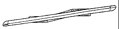
L'invention concerne un lien (14) de courroie modulaire comprenant une base (22) pourvue d'au moins un élément (32) d'articulation servant à connecter le lien (14) à des liens adjacents. Un élément de protection (16) est fixé à la base (22) du lien, et définit une paroi non plane (48) comprenant une partie inférieure (44) et une partie supérieure (42) reliées par les côtés (46). La paroi (48) est tordue par rapport à un axe de rotation (50) s'étendant de la partie supérieure (42) à la partie inférieure (44).


Abrégé anglais


A modular belt link (14) which includes a link base (22) having at least one
hinge barrel (32) for connecting the link (14) to adjacent links. A side guard
(16) is fixed to the link base (22), and defines a non-planar wall (48) having
a bottom (44) and top (42) joined by sides (46). The wall (48) is twisted
relative to an axis of rotation (50) extending through said top (42) and
bottom (44).

Revendications

Note : Les revendications sont présentées dans la langue officielle dans laquelle elles ont été soumises.


Claims
We claim:
1. A modular belt link comprising:
a link base having at least one hinge barrel for connecting the link to
adjacent links,
said link base having a direction of travel;
a side guard fixed to said link base, and defining a non-planar wall having a
bottom and top joined by sides, said wall being twisted relative an axis of
rotation extending
through said top and bottom.
2. The modular belt link as in claim 1, in which said bottom defines a first
angle
of rotation relative to said base direction of travel and said top defines a
second angle of
rotation relative to said base direction of travel, wherein said first and
second angles of
rotation are unequal.
3. The modular belt link as in claim 2, in which said second angle of rotation
is
greater than said first angle of rotation.
4. The modular belt link as in claim 1, in which said base includes a body,
and
said hinge barrel and said side guard are fixed to said body.
5. The modular belt link as in claim 4, in which said body includes a planar
top
surface, and said axis of rotation is substantially perpendicular to said top
surface.
6. The modular belt link as in claim 1, in which said bottom is thicker than
said
top.
7. The modular belt link as in claim 1, in which said base is formed as an
integral part of said side guard.

8. A side guard for use on a conveyor belt, said side guard comprising:
a non-planar wall defined by a top edge and bottom edge joined by side edges,
and including an axis of rotation extending between said top edge and said
bottom edge,
wherein said non-planar wall is twisted relative to said axis of rotation,
wherein a first
vertical plane defined by said bottom edge passes through said axis of
rotation, and a second
vertical plane defined by said top edge passes through said axis of rotation,
wherein said first
and second planes are not coplanar.
9. The side guard as in claim 8, including a link based fixed to said bottom
edge.
10. The side guard as in claim 9, in which said base is formed as an integral
part
of the side guard.
11. The side guard as in claim 8, in which said bottom edge is thicker than
said
top edge.
12. A belt link comprising:
a link base having at least one hinge barrel for connecting the link to
adjacent
links, said link base having a direction of travel;
a side guard fixed to said link base, and including a non-planar wall defined
by a top edge and bottom edge joined by side edges, said non-planar wall
including an axis of
rotation extending between said top edge and said bottom edge, wherein said
non-planar wall
is twisted relative to said axis of rotation.
13. The belt link as in claim 12, in which a first vertical plane defined by
said
bottom edge passes through said axis of rotation, and a second vertical plane
defined by said
top edge passes through said axis of rotation, wherein said first and second
planes are not
coplanar.

14. The belt link as in claim 12, in which said base is formed as an integral
part of
the side guard.
15. The belt link as in claim 12, in which said bottom edge is thicker than
said top
edge.

Description

Note : Les descriptions sont présentées dans la langue officielle dans laquelle elles ont été soumises.


CA 02450717 2007-07-06
LINK HAVING A TWISTED SIDE GUARD
Backaound Of The Invention
The present invention relates to modular conveyor chains, and more
particularly to
a side guard for use on a modular conveyor chain link.
Modular belting is formed from interconnected links which are supported by a
frame and driven to transport a product. Each link has a support surface which
supports the
product as the belting is being driven along the frame. In certain
applications, side guards are
fixed to, or are formed as an integral part of, the link to prevent a conveyed
load from falling
off of the belt. Side guards attached to the belt move with the product being
conveyed to
minimize relative motion between the support surface and the side guard.
Minimizing the
relative motion reduces product damage.
Prior art side guards, such as shown in Figs. 1-4, are fixed to a modular
belt, and
are arranged in overlapping relation to prevent large longitudinal gaps from
fonming when the
belt flexes around a drive or idle sprocket. The side guards are typically
attached to the belt
near the belt width edges, and are fixed at an angle, known as a shingle
angle, relative to the
belt edge to avoid interference between adjacent side guards.
The height of the side guard and amount of belt flexing required determines
the
extent of side guard overiap. As height or flexing requirements increase, more
overlap is
I

CA 02450717 2008-08-12
required to prevent gaps from opening up as the belt flexes. Increasing the
overlap, typically
requires a greater shingle angle to prevent interference between the side
guards as the belt flexes.
Increasing the shingle angle to prevent interference between the side guards
increases the clearance between adjacent side guards. When conveying small
products,
increasing overlap, and thus the shingle angle, between side guards is
undesirable because the
product can wedge between the side guards causing damage to the side guards
and the product.
Moreover, increasing the shingle angle causes the side guards to consume more
of the belt area,
thus reducing the usable area of the belt. Accordingly, a need exists for a
belt having a side guard
which can negotiate small sprockets without requiring a large shingle
clearance.
Summary Of The Invention
According to a first broad aspect of the present invention, there is provided
a
modular belt link comprising a link base having at least one hinge barrel for
connecting the link
to adjacent links, the link base having a direction of travel; a side guard
fixed to the link base,
and defining a non-planar wall having a bottom and top joined by sides, the
wall being twisted
relative an axis of rotation extending through the top and bottom.
According to a second broad aspect of the present invention, there is provided
a side guard for use on a conveyor belt, the side guard comprising a non-
planar wall defined by a
top edge and bottom edge joined by side edges, and including an axis of
rotation extending
between the top edge and the bottom edge, wherein the non-planar wall is
twisted relative to the
axis of rotation, wherein a first vertical plane defined by the bottom edge
passes through the axis
of rotation, and a second vertical plane defined by the top edge passes
through the axis of
rotation, wherein the first and second planes are not coplanar.
2a

CA 02450717 2008-08-12
According to a third broad aspect of the present invention, there is provided
a
belt link comprising a link base having at least one hinge barrel for
connecting the link to
adjacent links, the link base having a direction of travel; a side guard fixed
to the link base, and
including a non-planar wall defined by a top edge and bottom edge joined by
side edges, the non-
planar wall including an axis of rotation extending between the top edge and
the bottom edge,
wherein the non-planar wall is twisted relative to the axis of rotation.
A general objective of the present invention is to provide a side guard link
which
intends to minimize interferences while maximizing product support surface
area. This objective
is sought to be accomplished by twisting the side guard to increase clearances
at the side guard
top while minimizing the encroachment of the side guard bottom on the support
surface are of
the belt.
This and still other objectives and advantages of the present invention will
be
apparent from the description which follows. In the detailed description
below, preferred
embodiments of the invention will be described in reference to the
accompanying drawings.
These embodiments do not represent the full scope of the invention. Rather the
invention
2b

CA 02450717 2003-12-15
WO 03/002433 PCT/US02/19519
may be employed in other embodiments. Reference should therefore be made to
the claims
herein for interpreting the breadth of the invention.
Brief Descrintion Of The Drawings
[0011] Fig. 1 is a perspective view of prior art modular belt link having a
side guard;
[0012] Fig. 2 is a top view of the link of Fig. 1;
[0013] Fig. 3 is an elevational view of the link of Fig. 1;
[0014] Fig. 4 is an edge view of the link of Fig. 1;
[0015] Fig. 5 is a perspective view of a modular belt incorporating the
present invention;
[0016] Fig. 6 is a top view of the belt of Fig. 5; and
[0017] Fig. 7 is a sectional view along line 7-7 of Fig. 6.
[0018] Fig. 8 is a perspective view of the side guard link of Fig. 4;
[0019] Fig. 9 is a top view of the link of Fig. 8;
[0020] Fig. 10 is an elevational view of the link of Fig. 8;
[0021] Fig. 11 is an edge view of the link of Fig. 8.
Detailed Description Of The Invention
[0022] A modular conveyor belt 10, shown in Figs. 5-7, includes a plurality of
chain links
12 and side guard links 14. The links 12, 14 are pivotally linked to adjacent
links 12, 14 to
form the continuous belt 10. The side guard links 14 include side guards 16,
and are arranged
to define a continuous sidewall 18 which defines an edge of a belt support
area 20.
[0023] Referring to Figs. 8-11, each side guard link 14 includes a link base
22 including a
body 24 having a top surface 26 joined by lateral edges 28 and ends 30. Hinge
barrels 32 are
formed as an integral part of the link body 24 extend alternatively past the
opposing lateral
edges 28. Each hinge barrel 32 extending past the same lateral edge 28
includes an opening
34 which is aligned with a hinge barrel of an adjacent link to receive a hinge
pin 36 (shown
3

CA 02450717 2003-12-15
WO 03/002433 PCT/US02/19519
in fig. 5) which pivotally links the adjacent links 12, 14 together. Although
a link base having
a body is preferred, the base can be the hinge barrels without the body, such
as shown in Fig.
1-4, without departing from the scope of the present invention.
[0024] The side guard 16 is, preferably, formed as an integral part of the
link base 22, and
has a top 42 and bottom 44 joined by sides 46 which define a non-planar
wal148. The non-
planar wal148 extends substantially perpendicular to the link body top surface
24 and defines
a portion of one of the continuous sidewalls 18. Although forming the side
guard 16 as an
integral part of the link base 22 is shown, the side guard 16 can be fixed to
the link base 22
using methods known in the art, such as by welding, mechanical fasteners,
interference fits,
and the like without departing from the scope of the present invention.
Moreover, as
disclosed above, the side guard 16 can be fixed directly to the hinge barrels
32 without an
intervening link body 24, such as shown in Figs. 1-4, without departing from
the scope of the
present invention.
[0025] The non-planar wall 48 is twisted relative to an axis of rotation 50
extending
through the side guard top 42 and bottom 44. Preferably, the axis of rotation
50 is
perpendicular to the link top surface 24. As shown in Fig. 9, the amount of
twist is defined by
the difference between the angle A that the side guard bottom 44 is rotated
about the axis 50
relative to a link direction of trave141 and the angle B that the side guard
top 42 is rotated
about the axis 50 relative to the link direction of trave141. Advantageously,
the twisted side
guard 16 accommodates the increased interference requirement at the side guard
top 42
without decreasing the useable belt support area 20 proximal the side guard
bottom 44.
[0026] The amount of twist can also be quantified by an angle C defined by a
first
vertical plane 43 defined by the side guard bottom 44 and passing through the
axis of rotation
50 and a second vertical plane 45 defined by the side guard top 42 and passing
through the
axis of rotation 50. The two planes 43, 45 are not coplanar and intersect at
the axis of rotation
4

CA 02450717 2003-12-15
WO 03/002433 PCT/US02/19519
50 to define the angle C which is not 0 . Most preferably, the side guard top
42 is rotated
more than the side guard bottom 44.
[0027] The amount of twist is dependent upon the height of the side guard 16,
the greatest
amount of belt back flex required, and the desired clearances between adjacent
side guards
16. Providing a twisted side guard 16 is especially advantageous for conveyor
belts with
small pitches, such as less than one inch. Small pitch belts are generally
used to convey small
products which can pass between gaps 52 (shown in Fig. 6) between the side
guards 16, and
the belt is typically required to back flex to a tighter radii than longer
pitch belts.
[0028] The thickness of the side guard 16 can also be varied to minimize the
gaps 52
while maintaining required clearances between the adjacent side guards 16.
Preferably, as
shown in Fig. 7, the side guard wall thickness decreases from the side guard
bottom 44 to the
side guard top 42 to efficiently close the gaps 52 between the adjacent side
guards 16
proximal the side guard bottom 44 while providing the necessary clearance
proximal the side
guard top 42.
[0029] Referring back to Figs. 5 and 6, the side guard links 14 intermesh with
typical
chain links 12 to form the belt 10. As shown in Figs. 5 and 6, a typical chain
link 12, can
include a link body 54 having a top surface 56 joined by lateral edges 58 and
ends 60. Hinge
barrels 62 are formed as an integral part of the link body 54 extend
alternatively past the
opposing lateral edges 58, and interdigitively mate with hinge barrels 62
formed in an
adjacent link body 54. Each hinge barrel 62 extending past the same lateral
edge 58 includes
a coaxial opening 64 which receive a hinge pin 36 to pivotally link adjacent
links 12, 14
together.
[0030] The side guard links are, preferably, molded plastic, and formed as a
single piece.
However, the link base and side guard can be formed separately from the same
or different
materials, and comprise multiple pieces without departing from the scope of
the invention.

CA 02450717 2003-12-15
WO 03/002433 PCT/US02/19519
For example, the side guard can be formed from a metal, such as stainless
steel, which is
joined to a base formed from plastic, and vice versa, without departing from
the scope of the
claims.
[0031) While there has been shown and described what are at present considered
the
preferred embodiments of the invention, it will be obvious to those skilled in
the art that
various changes and modifications can be made therein without departing from
the scope of
the invention defined by the appended claims.
6

Dessin représentatif
Une figure unique qui représente un dessin illustrant l'invention.
États administratifs

2024-08-01 : Dans le cadre de la transition vers les Brevets de nouvelle génération (BNG), la base de données sur les brevets canadiens (BDBC) contient désormais un Historique d'événement plus détaillé, qui reproduit le Journal des événements de notre nouvelle solution interne.

Veuillez noter que les événements débutant par « Inactive : » se réfèrent à des événements qui ne sont plus utilisés dans notre nouvelle solution interne.

Pour une meilleure compréhension de l'état de la demande ou brevet qui figure sur cette page, la rubrique Mise en garde , et les descriptions de Brevet , Historique d'événement , Taxes périodiques et Historique des paiements devraient être consultées.

Historique d'événement

Description Date
Le délai pour l'annulation est expiré 2014-06-20
Lettre envoyée 2013-06-20
Inactive : IPRP reçu 2009-07-14
Accordé par délivrance 2008-11-04
Inactive : Page couverture publiée 2008-11-03
Exigences de modification après acceptation - jugée conforme 2008-08-28
Lettre envoyée 2008-08-28
Modification après acceptation reçue 2008-08-12
Préoctroi 2008-08-12
Inactive : Taxe de modif. après accept. traitée 2008-08-12
Inactive : Taxe finale reçue 2008-08-12
Un avis d'acceptation est envoyé 2008-02-15
Lettre envoyée 2008-02-15
Un avis d'acceptation est envoyé 2008-02-15
Inactive : Approuvée aux fins d'acceptation (AFA) 2007-11-30
Inactive : Demande ad hoc documentée 2007-11-02
Inactive : Supprimer l'abandon 2007-11-02
Inactive : Abandon. - Aucune rép dem par.30(2) Règles 2007-08-09
Modification reçue - modification volontaire 2007-07-06
Inactive : Dem. de l'examinateur par.30(2) Règles 2007-02-09
Inactive : IPRP reçu 2006-07-14
Inactive : Correspondance - Formalités 2006-07-04
Inactive : Correspondance - Formalités 2006-06-14
Inactive : CIB de MCD 2006-03-12
Lettre envoyée 2004-04-08
Inactive : Transfert individuel 2004-03-01
Inactive : Lettre de courtoisie - Preuve 2004-02-24
Inactive : Page couverture publiée 2004-02-20
Inactive : Acc. récept. de l'entrée phase nat. - RE 2004-02-18
Lettre envoyée 2004-02-18
Demande reçue - PCT 2004-01-13
Exigences pour l'entrée dans la phase nationale - jugée conforme 2003-12-15
Exigences pour une requête d'examen - jugée conforme 2003-12-15
Toutes les exigences pour l'examen - jugée conforme 2003-12-15
Demande publiée (accessible au public) 2003-01-09

Historique d'abandonnement

Il n'y a pas d'historique d'abandonnement

Taxes périodiques

Le dernier paiement a été reçu le 2008-06-16

Avis : Si le paiement en totalité n'a pas été reçu au plus tard à la date indiquée, une taxe supplémentaire peut être imposée, soit une des taxes suivantes :

  • taxe de rétablissement ;
  • taxe pour paiement en souffrance ; ou
  • taxe additionnelle pour le renversement d'une péremption réputée.

Les taxes sur les brevets sont ajustées au 1er janvier de chaque année. Les montants ci-dessus sont les montants actuels s'ils sont reçus au plus tard le 31 décembre de l'année en cours.
Veuillez vous référer à la page web des taxes sur les brevets de l'OPIC pour voir tous les montants actuels des taxes.

Historique des taxes

Type de taxes Anniversaire Échéance Date payée
Requête d'examen - générale 2003-12-15
Taxe nationale de base - générale 2003-12-15
TM (demande, 2e anniv.) - générale 02 2004-06-21 2003-12-15
Enregistrement d'un document 2004-03-01
TM (demande, 3e anniv.) - générale 03 2005-06-20 2005-06-17
TM (demande, 4e anniv.) - générale 04 2006-06-20 2006-06-14
TM (demande, 5e anniv.) - générale 05 2007-06-20 2007-06-11
TM (demande, 6e anniv.) - générale 06 2008-06-20 2008-06-16
2008-08-12
Taxe finale - générale 2008-08-12
TM (brevet, 7e anniv.) - générale 2009-06-22 2009-06-01
TM (brevet, 8e anniv.) - générale 2010-06-21 2010-06-01
TM (brevet, 9e anniv.) - générale 2011-06-20 2011-05-31
TM (brevet, 10e anniv.) - générale 2012-06-20 2012-05-30
Titulaires au dossier

Les titulaires actuels et antérieures au dossier sont affichés en ordre alphabétique.

Titulaires actuels au dossier
REXNORD CORPORATION
Titulaires antérieures au dossier
KEVIN S. HANSEN
PAUL M. KOEFERL
Les propriétaires antérieurs qui ne figurent pas dans la liste des « Propriétaires au dossier » apparaîtront dans d'autres documents au dossier.
Documents

Pour visionner les fichiers sélectionnés, entrer le code reCAPTCHA :


Pour visualiser une image, cliquer sur un lien dans la colonne description du document (Temporairement non-disponible). Pour télécharger l'image (les images), cliquer l'une ou plusieurs cases à cocher dans la première colonne et ensuite cliquer sur le bouton "Télécharger sélection en format PDF (archive Zip)" ou le bouton "Télécharger sélection (en un fichier PDF fusionné)".

Liste des documents de brevet publiés et non publiés sur la BDBC .

Si vous avez des difficultés à accéder au contenu, veuillez communiquer avec le Centre de services à la clientèle au 1-866-997-1936, ou envoyer un courriel au Centre de service à la clientèle de l'OPIC.

({010=Tous les documents, 020=Au moment du dépôt, 030=Au moment de la mise à la disponibilité du public, 040=À la délivrance, 050=Examen, 060=Correspondance reçue, 070=Divers, 080=Correspondance envoyée, 090=Paiement})


Description du
Document 
Date
(aaaa-mm-jj) 
Nombre de pages   Taille de l'image (Ko) 
Dessins 2003-12-14 4 69
Abrégé 2003-12-14 1 47
Revendications 2003-12-14 3 68
Description 2003-12-14 6 218
Dessin représentatif 2003-12-14 1 2
Description 2007-07-05 6 213
Revendications 2007-07-05 3 74
Description 2008-08-11 7 244
Dessin représentatif 2008-10-19 1 3
Accusé de réception de la requête d'examen 2004-02-17 1 174
Avis d'entree dans la phase nationale 2004-02-17 1 198
Courtoisie - Certificat d'enregistrement (document(s) connexe(s)) 2004-04-07 1 105
Avis du commissaire - Demande jugée acceptable 2008-02-14 1 164
Avis concernant la taxe de maintien 2013-07-31 1 171
PCT 2003-12-14 4 124
Correspondance 2004-02-17 1 25
Taxes 2005-06-16 1 40
Taxes 2006-06-13 1 23
Correspondance 2006-06-13 1 23
PCT 2003-12-15 4 144
Correspondance 2006-07-03 1 23
Taxes 2007-06-10 1 26
Correspondance 2008-08-11 1 30
Taxes 2008-06-15 1 27
PCT 2003-12-15 3 134