Sélection de la langue

Search

Sommaire du brevet 2450817 

Énoncé de désistement de responsabilité concernant l'information provenant de tiers

Une partie des informations de ce site Web a été fournie par des sources externes. Le gouvernement du Canada n'assume aucune responsabilité concernant la précision, l'actualité ou la fiabilité des informations fournies par les sources externes. Les utilisateurs qui désirent employer cette information devraient consulter directement la source des informations. Le contenu fourni par les sources externes n'est pas assujetti aux exigences sur les langues officielles, la protection des renseignements personnels et l'accessibilité.

Disponibilité de l'Abrégé et des Revendications

L'apparition de différences dans le texte et l'image des Revendications et de l'Abrégé dépend du moment auquel le document est publié. Les textes des Revendications et de l'Abrégé sont affichés :

  • lorsque la demande peut être examinée par le public;
  • lorsque le brevet est émis (délivrance).
(12) Brevet: (11) CA 2450817
(54) Titre français: ELEMENT A CONNEXION EN DEUX ETAPES
(54) Titre anglais: TWO-STEP CONNECTING ELEMENT
Statut: Durée expirée - au-delà du délai suivant l'octroi
Données bibliographiques
(51) Classification internationale des brevets (CIB):
  • A47C 1/036 (2006.01)
  • A47C 7/38 (2006.01)
  • A47C 7/46 (2006.01)
(72) Inventeurs :
  • EKORNES, ARVE (Norvège)
  • KROVEL, JAN KARE (Norvège)
  • BUEIDE, JOSTEIN (Norvège)
(73) Titulaires :
  • EKORNES ASA
(71) Demandeurs :
  • EKORNES ASA (Norvège)
(74) Agent: KIRBY EADES GALE BAKER
(74) Co-agent:
(45) Délivré: 2011-02-01
(86) Date de dépôt PCT: 2002-07-05
(87) Mise à la disponibilité du public: 2003-01-16
Requête d'examen: 2007-02-02
Licence disponible: S.O.
Cédé au domaine public: S.O.
(25) Langue des documents déposés: Anglais

Traité de coopération en matière de brevets (PCT): Oui
(86) Numéro de la demande PCT: PCT/NO2002/000248
(87) Numéro de publication internationale PCT: NO2002000248
(85) Entrée nationale: 2003-12-16

(30) Données de priorité de la demande:
Numéro de la demande Pays / territoire Date
20013342 (Norvège) 2001-07-05

Abrégés

Abrégé français

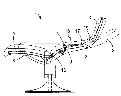
L'invention concerne un dispositif se trouvant dans une chaise (1), notamment une chaise à dossier réglable (2) et à appui-tête (3), dans lequel au milieu d'une section de l'appui-tête (3) et d'une section de fixation sur la construction de la chaise, un élément de connexion (18) est disposé au moyen par exemple d'une tige (17), qui par le mouvement du dossier réglable de la chaise (2) est disposé de manière à modifier l'angle de l'appui-tête (3) par rapport au dossier de la chaise (2) et en vue de donner des instructions à un appui-tête qui par des moyens simples peut être déboîté dans une position inclinée du dossier de la chaise, cette invention a prévu une rainure (21), un dispositif de blocage (22) et un organe de couplage (24) s'appliquant à la position inclinée du dossier de la chaise de façon manuelle ou automatique.


Abrégé anglais


The present invention concerns a device in a chair (1), especially a chair
with an adjustable back of the chair (2) and head rest (3), in that in between
a section of the head rest (3) and an attachment section on the chair
construction is arranged a connecting element (18) with for example a rod
(17), which by movement of the adjustable back of the chair (2) is arranged to
affect the angle of the head rest (3) in relation to the back of the chair
(2), and for the purpose of giving instructions on a head rest that by simple
means be uncoupled in a reclined position of the back of the chair, there is
according to the invention proposed a groove (21), a blocking device (22) and
a coupling organ (24) which come into effect in the reclined position of the
back of the chair, either in a manual or automatic way.

Revendications

Note : Les revendications sont présentées dans la langue officielle dans laquelle elles ont été soumises.


8
claims
1. Connecting element for a chair (1), with adjustable back
of the chair (2) and head rest (3), for positioning between
a section on the head rest (3) and an attachment section on
the chair, which by movement of the adjustable back of the
chair (2) is arranged to affect the angle of the head rest
(3) in relation to the back of the chair (2), in that the
angle of the head rest in the reclined position of the back
of the chair (2) may be changed by altering the effective
length of the connecting element, in that the connecting
element (18) comprises a guide (20) that receives a slider
(23) that may be locked in relation to each other,
characterised in that the guide (20) and the slider (23)
cooperate with a gravity influenced blocking device (22),
to cause a locked connecting position for the connecting
element (18) in a short state of the connecting element.
2. ~Connecting element according to claim 1,
characterised in that the connecting element (18) is
accomplished with a stopping device (25) that limits the
outer movement of the slider (23) in the guide (20).
3. ~Connecting element according to claim 2,
characterised in that the stopping device (25) consists of
a stopper attached to the guide (20) that runs in a track
(26) in the slider (23), which track limits the movement of
the slider (23) in the guide (20) to a first end
restriction (C) and likewise hinders that the slider (23)
is pulled out of the guide (20) by a second end restriction
(D).
4. ~Connecting element according to claims 1-3,
characterised in that the guide (20) of the connecting
element (18) and/or slider (23) and/or rod (17) is made of
a mouldable material such as a plastic material.

9
5. ~Connecting element according to the claims 1-4,
characterised in that the connecting element (18) is
equipped with a rod (17) that may be partly made of a
flexible material and/or is slightly arched or contains at
least a slight angle.
6. ~Connecting element according to the claims 1-5,
characterised in that the rod (17) is further attached to
the slider (23) in a way which allows rotation and/or
variation of the angle between them
7. ~Connecting element according to the claims 1-6,
characterised in that the connecting element has a cross
section which is mainly circular, oval, square or multi-
sided, preferably circular.
8. ~Connecting element according to the claims 1-7,
characterised in that the blocking device (22) is in the
form of a sphere or a cylinder or other movable blocking
device, preferably a sphere.
9. ~Chair (1) with adjustable back of the chair (2) and head
rest (3), with a connecting element according to one of the
preceding claims, arranged between a section on the head
rest (3) and an attachment section on the chair, which by
movement of the adjustable back of the chair (2) is
arranged to affect the angle of the head rest (3) in
relation to the back of the chair (2), in that the angle
of the head rest in the reclined position of the back of
the chair (2) may be changed by altering the effective
length of the connecting element,
characterised in that the blocking device (22) in an
upright position of the back of the chair (2) is locked
between a shallow part (A) of the coupling organ (24) in
the slider (23) and groove (21) in the guide (20) to
perform the head rest function until the back of the chair
is totally reclined,

10
- and in that a small (manual) forward pull of the head
rest in the reclined position of the back of the chair will
release the blocking device (22) from the locked position
and fall down in the deeper position (B) of the coupling
organ (24) due to gravity, in order to uncouple the head
rest (3),
- and in that the blocking device (22) first in a new
upright position of the back of the chair (2) again will
fall down between the shallow part (A) in the coupling
organ (24) in the slider (23) and groove (21) in guide (20)
in order to regain the function of the head rest in
cooperation with the connecting element (18).
10. Chair according to claim 9,
characterised in that it comprises a driver (30) attached
between the head rest (3) and the back of the chair (2)
limiting the rotational movement of the head rest, in
addition to a connecting element according to any claims
1-9.

Description

Note : Les descriptions sont présentées dans la langue officielle dans laquelle elles ont été soumises.


CA 02450817 2003-12-16
WO 03/003879 PCT/N002/00248
1
Two-step Connecting Element
Background of the Invention
The present invention relates to a length-adjustable
connecting element for a chair, with adjustable back of the
s chair and head rest, arranged between the head rest and the
chair construction, which by movement of the adjustable
back of the chair is arranged to affect the angle of the
head rest in relation to the back of the chair, as the
angle of the head rest may be altered by changing the
effective length of the connecting element in the reclined
position of the back of the chair.
Prior Art
From WO 92/06621, which is incorporated herein as
reference, a device for a chair with adjustable back of the
~s chair and head rest is known, wherein the head rest may be
adjusted in relation to the relative reclining positions of
the back of the chair, using a telescopic length adjustable
connecting element that stretches between the head rest and
a suitable location on the chair. This device has relative
zo complicated and expensive regulating organs and locking
organs which must be operated through the upholstery of the
chair, and they are difficult to make functioning in a
satisfactory way.
Purpose of the Invention
as The basis of the present invention lies in the object of
presenting a connecting element that comprises simple
parts, that is robust and dependable and that is silent in
use.
An additional object of the present invention is to provide
so a connecting element with manual or automatic adjustment
that may be adapted to any chair with a head rest,

CA 02450817 2003-12-16
WO 03/003879 PCT/N002/00248
2
including such chairs having arched guides, and also such
chairs with adjustable lower back support.
Short Description of the Invention
The aforementioned objects are achieved by a device of the
s introductory given kind, which according to the invention
is characterised by the features evident from the enclosed
patent claim 1.
Additional features and advantages of the present invention
will be apparent from the following description taken in
to association with the enclosed drawings, and the additional
enclosed patent claims.
Short Description of the Drawings
Fig. 1 is a phantom drawing of a chair according to the
invention seen from the side, wherein the back of the chair
~s is in a reclined position, simultaneously as the head rest
is shown in a reclined position in dotted line.
Fig. 2-5 depicts different positions of the head rest in
relation to the back of the chair, in one embodiment of the
connecting element according to the present invention, in a
no length profile .
Fig. 6 and 7 depicts the connecting element in fig 2-5 in a
locked and an uncoupled position, respectively, in larger
detail.
Description of Bmbodimeats
is On fig. 1 the framework of a chair 1 of the type disclosed
in WO 92/06621 is mainly shown, which chair 1 comprises an
adjustable back of the chair 2 with an adjustable head rest
3.

CA 02450817 2003-12-16
WO 03/003879 PCT/N002/00248
3
It should be understood that the chair specified in fig. 1
has a special adjustment of the head rest 3. The head rest
is active in that it maintains an upright position when the
back of the chair is reclined. In the reclined position of
s the back of the chair this function of the head rest may be
disconnected by pulling the head rest somewhat forward. The
head rest may then be reclined.
In fig. 1 the back of the chair 2 is supported about an
axis of rotation 9 making it possible for the back of the
chair 2 to take different angular positions, as the back of
the chair in the lower part at the same time has a
connection joint 10 to the chair seat 5, which is
accomplish by a known movement mechanism 8.
In fig. 1 a connecting element 18 with a rod 17 is also
~s shown, which is attached at the top to a joint 19 on the
head rest, and which in the lower part is attached to a
joint 7 on a permanent part of the framework of the chair,
in a distance from the axis of rotation 9. The connecting
element 18 with the rod 17 may take mainly two different
ao length positions and has its shortest length amongst others
when the back of the chair 2 is in an upright position,
wherein the head rest 3 is almost an extension of the back
of the chair 2, and forms its largest angle (almost 180°)
with the back of the chair. When the back of the chair 2 is
as reclined to the position shown in fig. 1, the relative
movement of the back of the chair 2, and the connecting
element 18 with the rod 17, will imply that the head rest 3
is pulled forward to a steeper angle in relation to the
back of the chair 2. With the help of a mechanism, the
ao connecting element may then be lengthened, so that the head
rest may be reclined to the dotted position 3'.
In fig. 2-5 one embodiment for a connecting element
according to the present invention is shown.

CA 02450817 2003-12-16
WO 03/003879 PCT/N002/00248
4
In this embodiment the connecting element 18 comprises
groove 21, blocking device 22 and coupling organ 24 which
cooperate with each other so that the head rest 3 may be
affected in the above mentioned ways by changing the length
s of the connecting element. The length of the connecting
element 18 is further restricted in this embodiment by the
stopping device 25 and track 26.
In fig. 6 and 7 it is shown in greater detail that the
connecting element 18 comprises a guide 20 in the form of a
circular cylinder, a blocking device 22 in the form of a
sphere, a slider 23 and a stopping device 25. The coupling
organ 24 is in the form of a first track in slider 23,
wherein the coupling organ 24 has a more shallow part A and
a deeper part B, which cooperate with the blocking device
~s 22 and a groove 21 in guide 20.
Likewise, it may from fig. 6 and 7 be seen that the
connecting element may comprise a track 26 in slider 23
with end restrictions C and D which cooperate with a
stopping device 25 placed in a hole in guide 20. The
zo stopping device 25 is held in place in guide 20 by a spring
ring 27 surrounding the guide 20.
The main parts of the connecting element, such as the guide
20, the slider 23, and the rod 17 may be produced in a
mouldable material such as a plastic material.
zs In an upright position of the back of the chair 2, the
blocking device 22 will fall down between the shallow
position A in the coupling organ 24 in the slider 23 and
the groove 21 in the guide 20, due to gravity as is evident
from fig. 2. When the back of the chair 2 is reclined as
3o shown in fig. 3, the head rest function is locked. In the
reclined position of the back of the chair 2 as shown in 4,
a small (manual) pull forwards of the head rest 3 will
release the blocking device 22 out of clamp between the
shallow position A in the coupling organ 24 and the groove

CA 02450817 2003-12-16
WO 03/003879 PCT/N002/00248
21, down into the deeper position B of the coupling organ
24 due to gravity, and thereby uncouple the head rest as
shown in fig. 5. This implies that the slider 23 will move
in the guide 20, and not fall down between position A in
s the coupling organ and the groove 21 until in a new upright
position of the back of the chair 2. when the back of the
chair 2 is reclined down again, the blocking device 22 will
lock the slider 23 to the guide 20 and the head rest
function is regained in cooperation with the connecting
element 18.
The movement of the head rest 3 is further restricted in
this embodiment by the movement of the slider 23 in guide
20 being restricted by the guiders stopping device 25,
which run in the gliders track 26 between the end
~s restrictions C and D. This restricts the movement of the
head rest forward, in upright position, as the slider 23
may not be moved further into the guide 20 than when the
stopping device 25 stands against the end restriction C in
track 26, see fig 1 and fig 6. In the reclined position of
zo head rest 3, the movement both forward and backwards is
restricted, where the latter is of most current interest in
that the slider 23 moves in the direction out of the guide
20 until the stopping device 25 stands against end
restriction D in then track 26, see fig. 5 and 7.
is In the embodiment shown in fig. 2-5 the chair is further
equipped with a driver 30 attached to the back of the chair
in its one end and to the joint 19 on the head rest in its
other end by a track 31, as shown in fig. 4. The driver 30
secures the head rest 3 against backward distortion in the
so reclined position, and brings the head rest 3 with it when
the back of the chair 2 is raised up such that the slider
23 moves all the way down into the guide 20 in the upright
position, making the blocking device 22 fall down between
the groove 21 and position A in the coupling organ 24
as again.

CA 02450817 2003-12-16
WO 03/003879 PCT/N002/00248
6
In other embodiments the stopping device with track as
described over may be arranged on other places in the
connecting element than shown in the figures, or on other
movable parts between the back of the chair 2 and the head
rest 3, such as for example on the arched guides of the
head rest or as separate stopping devices similar to the
driver 30, or the function may be attended by the
upholstery.
The driver 30 may likewise be arranged on other places
~o between the back of the chair 2 and the head rest 3, or its
function may be attended by the upholstery for example, or
devices in the arched guides of the head rest. Further, the
driver 30 may be constructed in other ways such as a wire
or a similar flexible organ with a certain length.
~s The connecting element may in its upper end be formed as a
rod 17, which is fastened in the joint 19 on the head rest.
The rod part may have a shape which gives a suitable
elastic flexibility. Alternatively the rod may be somewhat
arched or contain at least one slight angle. Further, the
ao rod 17 may be attached to the slider 23 in a way that
allows rotation and/or variation of the angle between them.
A person skilled in the art will understand that the
embodiment over is only one example, and that the invention
is restricted only by the claims enclosed. The guide 20
as with slider may have another cross section than circular,
such as for example oval or square. Likewise the blocking
device 22 may be a roll or another element influenced by
gravity. The coupling organ 24 and the groove 21 may have
another suitable design adapted to the blocking device 22,
3o such as a simple v-formed track which secures the above
mentioned function of the groove 21, blocking device 22 and
coupling organ 24.
Even if it is preferable both in technical production and
in costs to produce most of the parts of the connecting

CA 02450817 2003-12-16
WO 03/003879 PCT/N002/00248
7
element according to the invention from a mouldable plastic
material, it will be understood that other materials such
as metal or sintered materials may be used.

Dessin représentatif
Une figure unique qui représente un dessin illustrant l'invention.
États administratifs

2024-08-01 : Dans le cadre de la transition vers les Brevets de nouvelle génération (BNG), la base de données sur les brevets canadiens (BDBC) contient désormais un Historique d'événement plus détaillé, qui reproduit le Journal des événements de notre nouvelle solution interne.

Veuillez noter que les événements débutant par « Inactive : » se réfèrent à des événements qui ne sont plus utilisés dans notre nouvelle solution interne.

Pour une meilleure compréhension de l'état de la demande ou brevet qui figure sur cette page, la rubrique Mise en garde , et les descriptions de Brevet , Historique d'événement , Taxes périodiques et Historique des paiements devraient être consultées.

Historique d'événement

Description Date
Inactive : Périmé (brevet - nouvelle loi) 2022-07-05
Représentant commun nommé 2019-10-30
Requête pour le changement d'adresse ou de mode de correspondance reçue 2018-01-09
Accordé par délivrance 2011-02-01
Inactive : Page couverture publiée 2011-01-31
Préoctroi 2010-11-15
Inactive : Taxe finale reçue 2010-11-15
Un avis d'acceptation est envoyé 2010-07-07
Lettre envoyée 2010-07-07
month 2010-07-07
Un avis d'acceptation est envoyé 2010-07-07
Inactive : Approuvée aux fins d'acceptation (AFA) 2010-07-05
Modification reçue - modification volontaire 2010-05-31
Inactive : Dem. de l'examinateur par.30(2) Règles 2010-05-07
Modification reçue - modification volontaire 2009-12-14
Inactive : Dem. de l'examinateur par.30(2) Règles 2009-06-12
Modification reçue - modification volontaire 2009-02-03
Inactive : Dem. de l'examinateur par.30(2) Règles 2008-09-03
Lettre envoyée 2007-03-19
Requête d'examen reçue 2007-02-02
Exigences pour une requête d'examen - jugée conforme 2007-02-02
Toutes les exigences pour l'examen - jugée conforme 2007-02-02
Modification reçue - modification volontaire 2007-02-02
Inactive : CIB de MCD 2006-03-12
Lettre envoyée 2005-04-15
Inactive : Transfert individuel 2005-03-07
Inactive : Page couverture publiée 2004-02-18
Inactive : Lettre de courtoisie - Preuve 2004-02-17
Inactive : Notice - Entrée phase nat. - Pas de RE 2004-02-13
Demande reçue - PCT 2004-01-14
Exigences pour l'entrée dans la phase nationale - jugée conforme 2003-12-16
Demande publiée (accessible au public) 2003-01-16

Historique d'abandonnement

Il n'y a pas d'historique d'abandonnement

Taxes périodiques

Le dernier paiement a été reçu le 2010-06-04

Avis : Si le paiement en totalité n'a pas été reçu au plus tard à la date indiquée, une taxe supplémentaire peut être imposée, soit une des taxes suivantes :

  • taxe de rétablissement ;
  • taxe pour paiement en souffrance ; ou
  • taxe additionnelle pour le renversement d'une péremption réputée.

Les taxes sur les brevets sont ajustées au 1er janvier de chaque année. Les montants ci-dessus sont les montants actuels s'ils sont reçus au plus tard le 31 décembre de l'année en cours.
Veuillez vous référer à la page web des taxes sur les brevets de l'OPIC pour voir tous les montants actuels des taxes.

Titulaires au dossier

Les titulaires actuels et antérieures au dossier sont affichés en ordre alphabétique.

Titulaires actuels au dossier
EKORNES ASA
Titulaires antérieures au dossier
ARVE EKORNES
JAN KARE KROVEL
JOSTEIN BUEIDE
Les propriétaires antérieurs qui ne figurent pas dans la liste des « Propriétaires au dossier » apparaîtront dans d'autres documents au dossier.
Documents

Pour visionner les fichiers sélectionnés, entrer le code reCAPTCHA :


Pour visualiser une image, cliquer sur un lien dans la colonne description du document (Temporairement non-disponible). Pour télécharger l'image (les images), cliquer l'une ou plusieurs cases à cocher dans la première colonne et ensuite cliquer sur le bouton "Télécharger sélection en format PDF (archive Zip)" ou le bouton "Télécharger sélection (en un fichier PDF fusionné)".

Liste des documents de brevet publiés et non publiés sur la BDBC .

Si vous avez des difficultés à accéder au contenu, veuillez communiquer avec le Centre de services à la clientèle au 1-866-997-1936, ou envoyer un courriel au Centre de service à la clientèle de l'OPIC.

({010=Tous les documents, 020=Au moment du dépôt, 030=Au moment de la mise à la disponibilité du public, 040=À la délivrance, 050=Examen, 060=Correspondance reçue, 070=Divers, 080=Correspondance envoyée, 090=Paiement})


Description du
Document 
Date
(aaaa-mm-jj) 
Nombre de pages   Taille de l'image (Ko) 
Revendications 2003-12-15 3 105
Abrégé 2003-12-15 2 66
Description 2003-12-15 7 261
Dessins 2003-12-15 6 100
Dessin représentatif 2003-12-15 1 13
Description 2009-02-02 8 317
Revendications 2009-02-02 4 113
Description 2009-12-13 8 323
Revendications 2009-12-13 4 113
Revendications 2010-05-27 4 113
Dessin représentatif 2011-01-11 1 12
Avis d'entree dans la phase nationale 2004-02-12 1 190
Demande de preuve ou de transfert manquant 2004-12-19 1 102
Courtoisie - Certificat d'enregistrement (document(s) connexe(s)) 2005-04-14 1 104
Rappel - requête d'examen 2007-03-05 1 116
Accusé de réception de la requête d'examen 2007-03-18 1 176
Avis du commissaire - Demande jugée acceptable 2010-07-06 1 164
PCT 2003-12-15 6 261
Correspondance 2004-02-12 1 25
Correspondance 2010-11-14 1 35