Note : Les descriptions sont présentées dans la langue officielle dans laquelle elles ont été soumises.
CA 02451340 2003-11-27
SURFACE MOUNT FLUORESCENT STRIP LIGHT FIXTURE RETROFIT KIT
AND METHOD
BACKGROUND OF THE INVENTION
This invention relates to surface mount fluorescent strip
light fixtures, and, more particularly, to a retrofit kit and
method of retrofitting for surface mount fluorescent strip
light fixtures.
Surface mount fluorescent strip light fixtures are
installed to provide general lighting of large indoor spaces.
It should be understood that the description of the fixtures
as 'surface mount' type fixtures is intended to distinguish
the fixtures from 'recessed' type fixtures. Thus, the
invention taught herein will apply to all 'surface mount' type
fluorescent strip light fixtures, including stem and pendant
mounted suspended variations as well as those fixtures mounted
directly to a ceiling.
Typically, such strip fixtures include a channel in the
form of an inverted trough, with the channel being attached to
the ceiling. Lamp holders (sockets) are attached to the
channel. A ballast is attached within the channel and wiring
attaches the ballast to the lamp holders. Power is supplied
to the ballast by wiring brought into the channel through the
top or end of the channel. A ballast cover is used to close
the open face of the channel so that the ballast and wiring
are enclosed. Linear
1
CA 02451340 2003-11-27
fluorescent lamps are then placed in the lamp holders for
operation of the fixture. The lamps are left bare and exposed
for providing light to the space. Because of their low cost
and utilitarian use, the surface mount fluorescent strip light
fixture is the best selling light fixture of all time. Thus,
as used herein, surface mount fluorescent strip light fixtures
shall be understood to include all fixtures having this basic
configuration.
Typical uses include retail stores, such a grocery, drug,
and department stores, where the fixtures are commonly mounted
in continuous rows. The fixtures are also used in warehouses.
Since the introduction of the fluorescent lamp at the
1939 World Fair, fluorescent lighting technology has greatly
advanced. Particularly in response to the energy crisis of the
1970's and the National Energy Policy Act of 1992, lamp and
ballast manufacturers have developed fluorescent lamp-ballast
systems with improved efficiencies. For example, electronic
ballasts are now capable of more efficient operation than
older technology magnetic ballasts. Additionally, the newer,
energy saving fluorescent lamps have special lamp holder
and/or ballast requirements.
There are a large number of fixtures in the market that
use obsolete technology. Consumers desire to reduce their
utility costs, and the newer technology can save 25%, or
better, in such costs. However, for existing installations,
implementation of the newer technology means either replacing
the individual fixture components (ballast, lamp holders,
wiring, and lamps) or replacing the fixtures all together.
Both processes are time consuming and labor intensive,
requiring 30 minutes or so for each fixture retrofit or
replacement. Further, the retrofit process requires closing
down sections of a store during the construction, increasing
the impact of the time and effort required to retrofit or
replace the old fixtures. Thus, there is a need for a retrofit
2
CA 02451340 2011-09-26
53873-71
kit and method for surface mount fluorescent strip light fixtures that can be
installed
with a minimum of time and labor.
Additionally, current retrofit or replacement options for old fixtures
requires disposal of the old ballast, lamp holders, wiring, and lamps, or the
entire
fixture all together, creating disposal costs and other issues. For instance,
many old
ballasts contain hazardous materials and require disposal treatment as such.
Thus,
there is a further need for a retrofit kit and method for surface mount
fluorescent strip
light fixtures that minimizes the disposal issues of the retrofit process.
BRIEF SUMMARY OF THE INVENTION
Thus, it is an object of some embodiments of the present invention to
provide a retrofit kit and method of retrofitting existing fluorescent strip
light fixtures
with a replacement lamp-ballast system.
It is a further object of some embodiments of the present invention to
provide a kit and a method for retrofitting an existing fluorescent strip
light fixture that
can be installed with a minimum of time and labor.
It is even a further object of some embodiments of the present invention
to provide a retrofit kit for an existing fluorescent strip light fixture that
minimizes the
disposal issues of the retrofit process.
In one of its aspects, the present invention provides a retrofit unit for a
fluorescent lighting fixture comprising a chamber having two side walls with a
downwardly protruding bottom wall depending therebetween for enclosing an
existing
fluorescent strip light fixture, said retrofit unit further having a ballast
in said chamber
affixed to said protruding bottom wall and a plurality of downwardly extending
lamp
holders, said ballast being substantially contained within said downwardly
protruding
bottom wall to accommodate an existing light fixture and an existing ballast
thereof.
3
CA 02451340 2011-09-26
53873-71
In another of its aspects, the present invention provides a retrofit unit for
a fluorescent lighting fixture comprising a downwardly projecting bottom
surface and
two oppositely attached side walls forming a chamber for enclosing an existing
fluorescent strip light fixture, said projecting bottom surface having at
least one pair of
opposing lamp holders extending downwardly and a ballast attached to said
projecting bottom surface and substantially contained therein to accommodate
an
existing light fixture and an existing ballast thereof.
In still another of its aspects, the present invention provides a retrofit
unit for a fluorescent lighting fixture comprising: a downwardly protruding
bottom wall
interposed between a first sidewall and a second sidewall forming an interior
chamber having open ends, said bottom wall having at least one pair of
opposing
lamp holders extending oppositely said interior chamber, said bottom wall
having a
ballast attached thereto and substantially contained therein to accommodate an
existing light fixture and an existing ballast thereof.
In a further aspect, the present invention provides a retrofit unit for a
fluorescent lighting fixture comprising: a retrofit unit forming an elongated
retrofit
channel having two side walls and a downwardly protruding bottom side; a
ballast
attached to an interior surface of said protruding bottom side and
substantially
contained therein to accommodate an existing light fixture and an existing
ballast
thereof; at least one pair of opposing lamp holders attached to an exterior
surface of
said retrofit channel; and a plurality of mounting brackets removably attached
to said
retrofit channel opposite said bottom side.
In still a further of its aspects, the present invention provides a retrofit
assembly for a fluorescent lighting fixture comprising: an existing
fluorescent lighting
fixture having an existing ballast and existing plurality of lamp holders; a
retrofit unit
forming an elongated retrofit channel surrounding said existing fluorescent
light
fixture, said elongated retrofit channel having two side walls with a
downwardly
protruding bottom wall depending therebetween; a retrofit ballast attached to
said
4
CA 02451340 2011-09-26
53873-71
downwardly protruding bottom wall of said retrofit channel to accommodate an
existing light fixture and an existing ballast thereof; at least one pair of
opposing lamp
holders attached to an exterior surface of said retrofit unit; and a plurality
of mounting
brackets removably attached to two opposing sides of said retrofit unit.
In yet a further aspect, the present invention provides a method for
retrofitting a fluorescent lighting fixture, consisting essentially of the
steps of:
disconnecting power to an existing fluorescent lighting fixture; removing
lamps and
ballast cover from said existing lighting fixture; placing a plurality of
mounting
brackets on top of said existing lighting fixture; hanging the retrofit unit
as described
above on said plurality of mounting brackets, wherein said plurality of
mounting
brackets cooperate with slots in a side of said retrofit unit; connecting
power and
ground leads to said retrofit unit; swinging up said retrofit unit adjacent
said plurality
of mounting brackets; and attaching said retrofit unit to said plurality of
mounting
brackets.
In still a further of its aspects, the present invention provides an
apparatus for retrofitting a fluorescent lighting fixture comprising: a
retrofit channel
forming member having a downwardly protruding bottom wall and pair of opposing
side walls; a retrofit ballast attached to said downwardly protruding bottom
wall and
substantially contained therein; at least one pair of opposing lamp holders
affixed to
said bottom wall; and a means for affixing said retrofit channel to an
existing
fluorescent lighting fixture.
BRIEF DESCRIPTION OF THE SEVERAL VIEWS OF THE DRAWINGS
Figure 1 shows an exploded view of an existing surface mount
fluorescent strip light fixture.
Figure 2 shows a partial perspective view of an existing surface mount
fluorescent strip light fixture and a retrofit kit according to the present
invention,
5
CA 02451340 2011-09-26
53873-71
particularly showing a mounting bracket attached to the existing fixture in
alignment
with slots in a retrofit channel.
Figure 3 shows a perspective view of an existing surface mount
fluorescent strip light fixture and the retrofit kit of the present invention,
particularly
showing the retrofit channel hanging on the mounting brackets.
6
CA 02451340 2003-11-27
Figure 4 shows a different perspective view of the
arrangement of Figure 3, particularly showing the ballast and
ballast wiring of the retrofit kit of the present invention.
Figure 4 is show with the second side wall door removed so
that the wiring details are more clearly visible.
Figure 5 shows a partial perspective view of an existing
surface mount fluorescent strip light fixture and the retrofit
kit of the present invention, particularly showing the
retrofit kit swung into position around the existing fixture.
Figure 6 is a partial perspective view of the mounting
bracket and door section outwardly turned flange of Figure 5.
Figure 7 is another view of the components of Figure 6,
with the thumb latch rotated into engagement with the door
section flange.
DETAILED DESCRIPTION OF THE INVENTION
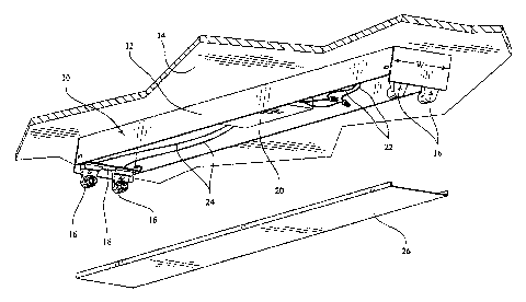
As shown in Figure 1, an existing surface mount
fluorescent strip light fixture 10 has an existing strip
channel 12 in the form of an inverted trough, with the
existing channel 12 being attached to a ceiling 14. As
mentioned earlier, surface mount type fluorescent strip
fixtures may also be suspended from a ceiling by a stem or
other pendant type suspension system, and it should be
understood that the principles taught herein will apply
equally to any surface mount type fluorescent strip fixture
whether it is suspended or mounted directly to a ceiling. The
existing channel 12 has a width, w, as shown, which is
typically around 4-1/8 inches to 4-1/4 inches. The existing
fixture 10 has lamp holders 16 which are commonly attached to
a saddle piece 18, which is, in turn, suspended between the
walls of the existing channel 12. The existing fixture also
has a ballast 20, which is contained within the existing
channel 12. Power is supplied to the ballast by power supply
7
CA 02451340 2003-11-27
leads 22 brought into the channel 12, and the ballast 20,
in turn, provides power to the lamp holders 16 by existing
lamp holder wiring 24. A ballast cover 26 covers the open face
of the existing channel 12 to enclose the ballast 20, power
wiring 22 and lamp holder wiring 24.
Preparation of the existing strip fixture 10 for
retrofitting with the retrofit kit and method of the present
invention includes: disconnecting power to the existing strip
fixture 10; removing the existing lamps (already removed from
the existing fixture shown in Fig. 1); and removing the
ballast cover 26. The existing lamps and the ballast cover 26
will be the only components of the existing strip fixture 10
which require disposal in the retrofit process according to
the instant invention.
As shown in Figures 2-7, the surface mount fluorescent
strip light fixture retrofit kit of the present invention is
comprised of two mounting brackets 28 and a retrofit channel
30. The brackets 28 attach to the existing strip channel 12.
The retrofit channel 30 hangs from the brackets 28 and wraps
around the remaining components of the existing fixture 10.
More specifically, as shown in Figure 2, each mounting
bracket 28 has a horizontal arm 32, a depending leg 34, and an
upturned hook section 36. The horizontal arm 32 has a first
end 38 and a second end 40 and a length, 1, which is longer
than the width, w, of the existing channel 12. The depending
leg 34 extends downward from the first end 38 of the
horizontal arm 32 and conforms generally to the shape of the
channel 12. The upturned hook section 36 extends upward and
outward from the bottom end of the depending leg 34, forming a
hook-like structure therewith. The depending leg 34 contains a
fastener hole 42. Preferably, the mounting brackets are made
of a heavy gauge (16 gauge or 18 gauge) galvanized steel for
strength.
The retrofit channel 30 has the form of a non-inverted
8
CA 02451340 2003-11-27
trough, generally, having a first side wall 44, a bottom
wall 46, and a second side wall 48 (shown only partially in
Fig. 2). As mentioned earlier, the retrofit channel 30 is
proportioned to wrap around the existing fixture 10, including
the existing channel 12, lamp holders 16, and ballast 20
without the need to remove or dispose of those components. The
first side wall 44 of the retrofit channel 30 has an upper end
50 with slots 52 formed therein. The slots 52 are each
configured to receive the upturned hook section 36 of the
mounting brackets 28.
As shown in Figure 3, multiple slots are formed along the
upper end 50 of the first side wall 44.
Thus, the mounting brackets 28 are installed to the
existing channel 12 by slipping each bracket 28 between the
ceiling and the existing channel 12 so that the upturned hook
section 36 lines up with a slot 52 in the retrofit channel 30,
as shown in Figure 2. A template may be utilized for this
alignment, or the installer may simply use a ruler or other
measuring device to make the alignment. Should the selected
position for installation of a bracket 28 be obstructed by a
fastener connecting the existing channel 12 to the ceiling, or
a boss on top of the existing channel 12, an alternate
location may be easily selected by relocating the mounting
bracket 28 to an alternate location free of obstructions that
lines up with an alternate slot 52. Should the existing
fixture 10 have a suspended mounting arrangement, the mounting
brackets can just be laid on top of the existing channel 12.
Should the existing channel 12 be mounted so close to the
ceiling that the mounting brackets 28 will not fit in the
space between the existing channel 12 and the ceiling, the
bracket may be driven through the space with a hammer.
Following positioning of the mounting brackets 28 on top of
the existing channel 12, small pilot holes may be created in
the existing channel 12 in alignment with the fastener holes
9
CA 02451340 2003-11-27
42 in the depending legs 34 of each mounting bracket 28.
Thus, the mounting brackets 28 may be fastened to the existing
channel 12 with fasteners, such as screws 54 through the
fastener holes 42 and the pilot holes.
Upon fastening of the mounting brackets 28 to the
existing channel 12, the retrofit channel 30 may be hung by
the slots 52 on the upturned hook sections 36 of the mounting
brackets 28, as best shown in Figure 3.
As shown in Figure 4, a retrofit ballast 56 and retrofit
lamp holders 58 are attached to the retrofit channel 30, and
are connected by retrofit lamp holder wiring 60. The design of
the retrofit kit and method of retrofitting of the present
invention enables attachment of the retrofit ballast 56 and
lamp holders 58, and the connection of the retrofit lamp
holder wiring 60 to be performed during the manufacturing of
the kit at the factory. Thus, the installer of the kit at the
retrofit site does not have to devote time or labor to these
tasks.
As further shown in Figure 4, the retrofit ballast 56 has
power leads 62 and the retrofit kit has a ground lead 64.
The next step in installation of the retrofit kit is to
disconnect the power supply leads 22 from the existing ballast
20 and connect the power supply leads 22 to the retrofit
ballast power leads 62. Additionally, the retrofit kit ground
lead 64 should be connected to a through feed ground wire or
other ground wire in the existing fixture.
The mounting bracket upturned hook section 36 and
retrofit channel slots 52 create a hinge that allows the
retrofit channel 30 to hang from the mounting brackets 28 in a
position such that interior portion of the retrofit channel 30
is accessible to the installer for making the described
electrical connections, as shown in Figures 3 and 4.
Further facilitating access to the installer for making
CA 02451340 2003-11-27
the electrical connections, the retrofit channel second
side wall 48, best shown in Figure 5, can be fabricated as
having a door section 66 and a lower section 68. In the
embodiment shown, the door section 66 is hinged to the lower
section 68 through the use of a plurality of T-slots 70 along
the upper end of the lower section (see Figure 4) and mating
hooks (not shown) formed along the lower edge of the door
section 66. This hinged arrangement of the door section 66 and
lower section 68 of the second side wall 48 enables the door
section 66 to be opened for easier access to the interior
portion of the retrofit channel 30.
It should be observed that the door section 66 has been
removed from the views of Figures 2-4 in order to more clearly
show the component details of those views. Thus, Figures 2-4
show only the lower section 68 of the second side wall 48 of
the retrofit channel 30. However, it should be understood that
the second side wall 48 of the embodiment shown includes both
the lower section 68 and the door section 66.
Returning now to the view of Figure 5, it is seen that
the top portion of the door section 66 has an outwardly turned
flange 72. Thus, after the wiring connections are completed,
the retrofit kit may be swung up such that the door section
flange 72 seats against the underside of the mounting bracket
second ends 40 (only one mounting bracket 28 shown in Figure
5).
As best shown in Figures 6 and 7, the underside of each
mounting bracket second end 40 has a thumb latch 74 rotatably
attached thereto by a rivet 76. Thus, the thumb latch 74 of
each mounting bracket second end 40 may be rotated out of the
way of the door section flange 72 so that it may seat against
the underside of each mounting bracket second end 40. Then,
the thumb latch 74 of each mounting bracket second end 40 may
be rotated so that it engages the under side of the door
section flange 72, thereby holding the door section 66, and
11
CA 02451340 2003-11-27
the retrofit channel 30 in place, as shown in Figure 5.
As further shown in Figure 5, the retrofit kit may
include end caps 78 which are configured to close the ends of
the retrofitted fluorescent strip light fixture, or the ends
of a row of retrofitted fixtures. The end caps 78 may be
attached to the assembly by any convenient means.
Continuing with the view of Figure 5, it is seen that the
wrap around arrangement of the retrofit channel 30 and the
existing channel 12 and existing lamp holders 16 creates a
chamber 80 for the retrofit ballast 56 and associated wiring
(see Figure 4) without requiring the removal of the existing
ballast 20 (and the associated disposal issues) and associated
wiring (see Figure 1).
Additionally, as shown in Figure 5, the wrap around
arrangement allows the retrofit channel bottom wall 46 to be
wider than the existing channel 12. Thus, on the embodiment
shown, the bottom wall may have a flat portion 82 in the
middle and angled portions 84 on either side of the flat
portion. This allows improved optical performance in the two-
lamp configuration shown. Additionally, this allows one-lamp
and three-lamp versions of the retrofit kit to be produced by
installation of lamp holders and a lamp on the flat portion 82
of the bottom wall 46.
Returning now to Figures 6 and 7, the embodiment of the
invention shown also has a fastener hole 86 located in the
thumb latch. Each mounting bracket second end 40 further has a
fastener hole 88 positioned to be in alignment with the thumb
latch fastener hole 86 when the thumb latch 74 is rotated into
engagement with the door section flange 72. Additionally,
fastener holes 90 are located at positions in the door section
flange 72 corresponding to the slots 52 in the first side wall
44 such that the fastener holes 90 will be in alignment with
the thumb latch fastener hole 86 and the mounting bracket
second end fastener hole 88. Thus, a fastener 92, such as a
12
CA 02451340 2003-11-27
screw, may be fastened through thumb latch fastener hole
86, flange fastener hole 90 and mounting bracket second end
fastener hole 88 to secure the thumb latch 74 in place and to
establish electrical ground continuity between the respective
components.
Returning now to Figure 2, the embodiment of the
invention shown also has a groove 94 positioned along the
upper end 50 of the retrofit channel first side wall 44 such
that the slots 52 are located at the bottom of the groove 94.
This configuration enables the installer to more easily
position each mounting bracket upturned hook section 36 in a
first side wall slot 52 for hanging the retrofit channel 30
from the mounting brackets 28. Additionally, this
configuration allows the first side wall groove 94 to seat
against the existing channel 12 in order to meet code
requirements.
The material of the retrofit channel 30 of the embodiment
shown and described is code gauge steel (26 gauge to 16
gauge). However, it should be noted that the retrofit channel
30 does not require the attachment of conduit thereto,
allowing selection of a thinner gauge material to meet code
requirements and providing for savings in material costs. The
retrofit channel may be formed on a press break, roll formed,
or formed by any other suitable method.
This description of the invention, including specific
dimensions and materials, shall not be construed as a
limitation of any invention hereafter claimed by the
inventors, as it will be readily apparent to those skilled in
the art that design choices may be made without departing from
the spirit or scope of the invention.
13