Note : Les descriptions sont présentées dans la langue officielle dans laquelle elles ont été soumises.
CA 02451943 2003-12-31
1
TITLE OF THE INVENTION:
Single shaft harness device for horse-drawn vehicle
FIELD OF THE INVENTION
The present invention relates to harness device, which
enables a horse to be secured to a horse-drawn vehicle by a
single shaft.
BACItGROUND OF THE INVENTION
1o United States Patents 5,410,863 (Mouzon 1995) discloses a
harness device which enables a horse to be secured to a horse-
drawn vehicle by a single shaft. A spherical ball is fixedly
secured to a saddle bow resting upon the horse. The shaft
connecting the horse to the horse-drawn vehicle has a socket
of a shape which is adapted to mate with the spherical ball.
Existing single shaft harness devices, such as disclosed
in the Mouzon patent, are solely intended for pulling
relatively light loads. If modifications were made to adapt
2o such devices to pulling heavy loads, then all horses that are
saddle broken could potentially be used as work animals.
SU1~ARY OF THE INVENTION
What is required is a single shaft harness device for a
horse-drawn vehicle better suited for heavy loads.
According to the present invention there is provided a
single shaft harness device for a horse-drawn vehicle which
includes a saddle. At least one girth strap is provided which
3o is adapted for attaching the saddle to a horse. A ball hitch
extends vertically from the saddle. At least one breast strap
is provided which is adapted to extend between opposed sides
of the saddle around a breast of the horse. At least one
stabilizer bar is provided having a first end and a second
end. The first end of the at least one stabilizer bar is
secured to the saddle. In a working position, the at least one
CA 02451943 2003-12-31
2
stabilizer bar extends substantially horizontally in parallel
spaced relation with the second end terminating at a buttocks
of the horse. At least one lower stabilizer bar strap is
provided which is adapted to extend under the horse to the at
least one stabilizer bar. At least one rear stabilizer bar
strap is provided which is adapted to secure the second end of
the at least one stabilizer bar to a rear of the horse.
Prior art devices, such as Mouzon, would move back and
1o forth as a force was exerted upon the ball hitch. This
movement was minimal and did not affect performance as long as
the loads were light and the travel surface relatively flat.
However, if one substantially increased the load and had the
horse pull that load uphill and downhill, the extent and force
of the movement was injurious to the horse. When the horse
went downhill under load, the weight of the load would cause
the saddle to pitch forward. Conversely, when the horse went
uphill under load, the weight of the load would cause the
saddle to pitch rearward. The harness, as described above, was
developed to prevent pitched movement of the saddle, and
thereby enable a horse to pull heavy loads uphill and downhill
without injury.
A single pole stabilizer bar with a crupper looped around
the base of the tail may be used. This variant, by its
simplicity, is convenient to harness and is adequate for light
duty work.
Although beneficial results may be obtained through the
3o use of the harness, as described above, the heavier the
anticipated loads the greater support that is required. Even
more beneficial results may, therefore, be obtained when there
is provided a pair of parallel stabilizer bars. The first end
of one of the stabilizer bars is pivotally secured to one of
the opposed sides of the saddle. The first end of another of
the stabilizer bars is pivotally secured to another of the
CA 02451943 2003-12-31
3
opposed sides of the saddle. The stabilizer bars extend
substantially horizontally in parallel spaced relation and can
pivot to accommodate movement of the horse during turns.
Although beneficial results may be obtained through the
use of the harness, as described above, one is relying upon
the saddle girth strap to limit side to side movement of the
saddle. Even more beneficial results may, therefore, be
obtained when front leg straps are provided. Each of the front
leg straps has a first end and a second end. The first end
depends from the breast strap. The second end depends from
the saddle. Each of the front leg straps are adapted to
extend around a front leg of the horse, and provide additional
lateral stability to the saddle.
Although beneficial results may be obtained through the
use of the harness, as described above, the second end of the
shaft is secured by to a vehicle. Even more beneficial
results may be obtained when the pivotal connection pivots
about a substantially horizontal pivot axis. This isolates
the movement of the horse at different gates, so that movement
of the horse is not felt by occupants of the vehicle.
Although beneficial results may be obtained through the
use of the harness, as described above, problems can be
encountered if the horse acts up. Even more beneficial
results may, therefore, be obtained when a remotely activated
quick release mechanism is provided to quickly disengage the
socket on the shaft from the ball hitch. The quick release of
the ball hitch/socket connection enables the horse to be
released, before the vehicle becomes overturned. A simple
manner of providing for remote activation is to have a line
which may be pulled to trigger release of the ball hitch.
Although beneficial results may be obtained through the
CA 02451943 2003-12-31
4
use of the harness, as described above, even more beneficial
results may be obtained when the second end of the shaft is
secured to a turntable on the vehicle to which wheels are
mounted. The turntable pivots about a substantially vertical
pivot axis to track movements of the horse. The horse does not
need assistance when turning a small load, however, as the
size of the vehicle and the size of the load is increased it
is beneficial to have the front wheels of the vehicle turn to
track movement of the horse.
to
Although beneficial results may be obtained through the
use of the harness, as described above, even more beneficial
results may be obtained when rump pad and a waste catcher are
adapted to the harness.
Although beneficial results may be obtained through the
use of the harness, as described above, even more beneficial
results may be obtained where the single stabilizer bar or the
pair of stabilizer bars are telescopically adjustable to suit
2o the build of the horse, allowing relatively quick changing
from one horse to the other.
Although beneficial results may be obtained through the
use of the harness, as described above, very heavy loads may
still require more support. Therefore, even more beneficial
results may be obtained when a horse collar is adapted to the
harness, allowing greater support for the horse to pull
heavier loads.
3o Although beneficial results may be obtained through the
use of the harness, as described above, even more beneficial
results may be obtained when the width of the saddle is
adjustable to accommodate different sizes of horses.
BRIEF DESCRIPTION OF T8E DRA~~INGS
These and other features of the invention will become
CA 02451943 2003-12-31
more apparent from the following description in which
reference is made to the appended drawings, the drawings are
for the purpose of illustration only and are not intended to
in any way limit the scope of the invention to the particular
5 embodiment or embodiments shown, wherein:
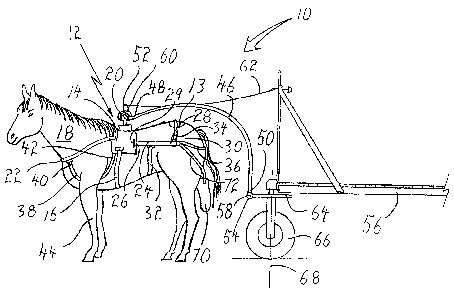
FIGURE 1 is a side elevation view of a single shaft
harness device for a horse-drawn vehicle constructed in
accordance with the teachings of the present invention with a
pair of stabilizer bars.
io FIGURE 2 is a side elevation view of a single shaft
harness device for a horse-drawn vehicle adapted with a single
pole stabilizer bar and a crupper.
FIGURE 3 is a detailed perspective view of an adjustable
stabilizer bar.
FIGURE 4 is a side elevation view of the single shaft
harness device for a horse-drawn vehicle illustrated in FIGURE
1 where a horse collar is adapted to the harness.
FIGORE 5 is a top plan view of a single shaft harness
device for a horse drawn vehicle illustrated in FIGURE 1
adapted for two horses.
FIGURE 6 is a perspective view of a single shaft harness
device for a horse drawn vehicle illustrated in FIGURE 1
adapted for three horses.
FIGURE 7 is a side elevation view of an adjustable saddle
with ball hitch.
FIGORE 8 is a top plan view of the adjustable saddle with
ball hitch illustrated in FIGORE 7.
DETAII~D DESCRIPTION OF T8~ PREFERRED EL~ODID~NT
3o The preferred embodiment, a single shaft harness device
for horse-drawn vehicle generally identified by reference
numeral 10, will now be described with reference to FIGURES 1
through 8.
Structure and Relationship of Parts:
Referring to FIGURE l~ harness 10 includes a saddle 12
CA 02451943 2003-12-31
6
having a rump pad 13, opposed sides 14 and at least ane strap
16 adapted for attaching saddle 12 to a horse 18. A ball
hitch 20 extends vertically from saddle 12. Saddle 12 is
further adapted with at least one breast strap 22 that extends
between opposed sides 14 of saddle 12 around a breast of horse
18. A pair of parallel stabilizer bars 24 (only one side is
shown) having a first end 26 and a second end 28 such that
first end 26 of one of stabilizer bars 24 is pivotally secured
to one of opposed sides 14 of saddle 12 and first end 26 of
another of stabilizer bars 24 is pivotally secured to another
of opposed sides 14 of saddle 12. In the illustrated
embodiment, first end 26 of stabilizer bar 24 is attached to
saddle 12 with a hinge 29. Referring to FIGURE 5, stabilizer
bars 24 extend substantially horizontally in parallel spaced
relation, with second end 28 of each of stabilizer bars 24
terminating adjacent to buttocks 30 of horse 18. Referring to
FIGURE 2, stabilizer bars 24 are further adapted with at least
one lower stabilizer bar strap 32 that extends under horse 18
between stabilizer bars 24, at least one upper stabilizer bar
strap 34 that extends over horse 18 between stabilizer bars 24
and at least one rear stabilizer bar strap 36 that extends
around buttocks 30 of horse 18 between second ends 28 of
stabilizer bars 24. In the illustrated embodiment, harness 10
is further adapted with front leg straps 38 having a first end
40 and a second end 42. Each first end 40 of leg straps 38
depends from breast strap 22 and each second end 42 depends
from saddle 12. Leg straps 38 are adapted to extend under and
around a front leg 44 of horse 18. Harness 10 works in
combination with a single shaft 46 having a first end 48 and a
second end 50. First end 48 of shaft 46 has a socket 52
adapted to engage ball hitch 20. Second end 50 of shaft 46 is
mounted to a pivotal connection 54 at vehicle 56. Pivotal
connection 54 pivots solely about a substantially horizontal
pivot axis 58. In the illustrated embodiment, harness 10 is
further adapted with a remotely activated quick release
mechanism 60 having a trigger line 62 such that ball hitch 20
CA 02451943 2003-12-31
7
can be quickly disengaged from socket 52 by a rider,
separating horse 18 from vehicle 56. In the illustrated
embodiment, pivotal connection 54 for single shaft 46 is
mounted onto a turntable 64 to which front wheels 66 of
vehicle 56 are secured. Turntable 64 pivots about a
substantially vertical pivot axis 68. The horizontal pivot
axis 58 isolates vehicle 56 from up and down movements
resulting from the gait of horse 18. Vertical pivot axis 68
of turntable 64 allows front wheels 66 of vehicle 56 to
l0 effectively track changes in direction of horse 18. In the
illustrated embodiment, harness 10 is further adapted with a
waste collection pouch 70. Pouch 70 is fastened to second end
28 of stabilizer bar 24 by pouch frame 72. Referring to
FIGURE 2. in the illustrated embodiment, harness 10 is adapted
with a single pole stabilizer bar 74 with a crupper 76.
Crupper 76 is looped around base of tail 78. Referring to
FIGURE 3. in the illustrated embodiment, single pole
stabilizer bar 74 has adjustment holes 80 and a locking pin
82. Referring to FIGURE 4, in the illustrated embodiment,
harness 10 is adapted with a horse collar 84 which distributes
heavy load 86 more effectively to the horse while pulling.
Operation:
The use and operation of single shaft harness device 10
will now be described with reference to FIGURES 1 through 4.
Referring to FIGURE 1, where vehicle 56 is to be drawn by
horse 18, saddle 12 is placed on the back of horse 18. Strap
16 is extended under horse 18 between opposed sides 14 of
saddle 12, securing saddle 12 in place on back of horse 18.
o Breast strap 22 is extended around horse 18 between opposed
sides of saddle 12, such that rearward movement of saddle 12
is limited. Referring to FIGURE 5, stabilizer bars 24 are
placed in a working position, extending substantially
horizontally in parallel spaced relation with first ends 26
pivotally secured to saddle 12 and second ends 28 of each of
stabilizer bars 24 terminating adjacent to buttocks 30 of
CA 02451943 2003-12-31
8
horse 18. Hinge 29 accommodates turning movement for horse
18. Referring to FIGURE 1, lower stabilizer bar strap 32 is
extended under horse 18 between stabilizer bars 24 thereby
limiting upward movement of stabilizer bars 24. Upper
stabilizer bar strap 34 is similarly extended over horse 18
between stabilizer bars 24 thereby limiting downward movement
of stabilizer bars 24. Rear stabilizer bar strap 36 is then
extended around buttocks 30 of horse 18 between second ends 28
of stabilizer bars 24 thereby limiting forward movement of
to saddle 12. Should further security of saddle 12 be needed,
each of leg straps 38 may be extended from opposed sides 14 of
saddle 12 between front legs 44 to breast strap 22, limiting
side to side motion of saddle 12. Once saddle 12 is secured,
socket 52 at first end 48 of shaft 46 is engaged to ball hitch
i5 20. Pivotal connection 54 at second end 50 of shaft 46 is
connected to vehicle 56 allowing for up and down movement
about substantially horizontal axis 58. Further flexibility
may be had where pivotal connection 54 is connected to
turntable 64 such that there is also movement about a
2o substantially vertical axis 68, turning front wheels 66.
Waste collection pouch 70 may be positioned below buttocks 30
and fastened to stabilizer bar 24 with pouch frame 72. Where
the invention is utilized according to the teachings of the
preferred embodiment, horse 18 is harnessed in a manner that
25 saddle 12 is maintained in a relatively stable position, so
that a rubbing irritation injury will not be caused to the
back of horse 18 as result of pitched movement when pulling a
load uphill or downhill. This allows any saddle broken horse,
to be used as a working animal, pulling vehicle 56 up hill and
3o down hill, while vehicle 56 is loaded with a relatively heavy
load. It is important to note that no weight from the vehicle
is transferred to the back of horse 18. Horse 18 only has to
bear a portion of the weight of the shaft on it's back. The
horizontal pivot axis 58 isolates vehicle 56 from up and down
35 movements resulting from the gait of horse 18. Vertical pivot
axis 68 of turntable 64 allows front wheels 66 of vehicle 56
CA 02451943 2003-12-31
9
to effectively track changes in direction of horse 18. In the
event that some difficulty is encountered with horse 18 or
there is a need to quickly separate vehicle 56, operation of
remotely activated quick release mechanism 60 by means of
trigger line 62 will quickly disengage horse 18. Referring to
FIGURE 2, single pole stabilizer bar 74 with crupper 76 may be
fitted to horse 18 by looping crupper 76 around base of tail
78. This may prove to be more convenient for light duty
loads. Single pole stabilizer bar 74 rests upon rump pad 13,
to which protects the back of horse 18 from chaffing. Referring
to FIGURE 3. single pole stabilizer bar 74 may then be
adjusted to the build of another horse by releasing locking
pin 82 and re-inserting it into desired adjustment hole 80.
Pair of stabilizer bars 24 (as shown in FIGURE 1) may also be
telescopically adjustable. Referring to FIGURE 4. when pulling
a heavy load 86, harness 10 adapted with horse collar 84 may
be used, providing horse 18 with more support for effective
pulling of heavy load 86.
Variations:
Referring to FIC~1RES 5 and 6, where more 'horse power' is
required, two, three or possibly more horses 18 may be used.
Referring to FIGURE 5, in the illustrated embodiment, harness
10 is adapted with a t-bar 88 with telescopic arms 90. T-bar
88 is attached to single shaft 46 with a cross pin connection
92 which permits relative rotational movement. It will be
appreciated that other means of attachment may be used.
Referring to FIGURE 6, in the illustrated embodiment, harness
10 is adapted with a pair of single shafts 46 connected to an
3o evener 94 with pins 96, evener 94 being attached at pivotal
connection 54. In order to accommodate a middle horse 19,
saddle 12 is adapted with two ball hitches 20. Two t-bars 88
are used to accommodate a horse 18 on each side of middle
horse 19. It will be noted that in adaptations for multiple
horses as shown in FIGURES 5 and 6r each harness as it applies
to each individual horse is provided according to the
CA 02451943 2003-12-31
teachings of the present invention and as illustrated in
FIGURES 1 through 4. Referring to FIGURE 7, where horses vary
in girth, saddle 12 may have a first part 98 adapted with a
first side member 100 and a second part 102 adapted with a
5 second side member 104. Referring to FIGURE 8, ball hitch 20
is attached to first side member 100. Second side member 104
has a slot 106 within which ball hitch 20 slides allowing
saddle 12 to adjust to different sizes of horses. In the
illustrated embodiment first side member 100 is secured to
1o second side member 104 with screw fasteners 108. It will be
appreciated that other means of fastening may be used.
Operation:
The use an operation of variations will now be described
with reference to FIGURES 5 through 8. Referring to FIGURE 5,
telescopic arms 90 are used to accommodate for any variations
in distance between horses during their normal working
movement. Relative rotational movement is provided between
single shaft 46 and t-bar 88 to accommodate transverse
movement over uneven ground, during which one horse 18 may be
positioned up hill and the other horse 18 may be positioned
downhill. Referring to FIGURE 6. this same rotational
requirement is met where there is a ball hitch 20 at each
connection to a horse 18 and pins 96 are loosely fitted to
allow sufficient movement. Referring to FIGURES 7 and 8,
where various sizes of horses are used, saddle 12 may be
adjusted to fit each individual horse.
In this patent document, the word "comprising" is used in
its non-limiting sense to mean that items following the word
are included, but items not specifically mentioned are not
excluded. A reference to an element by the indefinite article
"a" does not exclude the possibility that more than one of the
element is present, unless the context clearly requires that
CA 02451943 2003-12-31
11
there be one and only one of the elements.
It will be apparent to one skilled in the art that
modifications may be made to the illustrated embodiment
without departing from the spirit and scope of the invention
as hereinafter defined in the Claims.