Note : Les descriptions sont présentées dans la langue officielle dans laquelle elles ont été soumises.
CA 02452087 2003-12-03
z
SACKGR.~UND OI~ TT~~ TN~VEhITION
1. Field of the lnvez~tioz~
The present invention relates to a portable drilling rig far drilling water
wells or installing
geothermal pipe systeax~s in the ground. More specif~caliy, the present
invention is a
partable drilling rig that is removably mounted on a track bed" The rig pivots
to a
horizontal position on the truck bed for transport and pivots to a vertical
position for
drilling, or alternately, pivots to a slanted position far drilling at an
angle into the ground.
l~
~. l~escri.ption of the Related Art
Currently the drilling rigs that are used to drill water wells or 1:o install
underground
piping for use in geothermal heating and cooling installations are large and
can not be
easily driven into a small area, such as a back yard of an urban residence.
Also, current drilling tags are not constructed to allow the drive shaft that
rotates the pipe
drill string and drill bit to pivot sv that additional pipe segments can be
easily added to
the pipe drib string, or alternately, removed from the pipe dril:E string.
lrurther, most current drill rigs are not simple enough for a single person to
operate.
CA 02452087 2003-12-03
1~inally, other dz~ll rigs are pem~anently mounted to the vehicae on which
they are
transported, making the vehicle unsuitable for any other purpose.
The present invention addresses each of these problezxzs lay providing a dri
lling rig that is
small and is removably mounted to the bed of a truck. The driilling rig of the
present
xzzvezztion is designed with a pivoting swivel that allows a single operator
to easily operate
the rig to drill a well.
SUMMARY 4F THE INVLNTIfJN
to
The present invention relates to a portable drilling rig for drilling water
wells or installing
geothermal pipe systems in the ,ground. More specifically, the: present
invention is a
poztable drilling rig that is remc~vably mounted on a truck bed via a
supporting frame that
holds the rig on the truclf bed. "fhe zag is provided with a pivotal mast that
can be pivoted
1 S downward to a horizontal position for transpoz~t and can be pivoted upward
to a vertical
position to drill a vertical bore into the ground, or alternately, pivoted
upward to a
slanted, ofF vertical position for drilling an angled bare into the ground.
The mast is pivotally secured to an upwardly extending, supporting pivot leg
provided
ZO secured to the frame at the rear end of the rig. The mast is raised and
lowered by a first
hydraulic cylinder that causes the mast to pivot at the supportiing pivot leg.
When the
mast is pivoted downward to its horizontal position, the upper end of the mast
is
CA 02452087 2003-12-03
4
supported by an upwardly extezzdin g, front support leg secured to the frame
at the front of
the frame.
Both the support pivot leg and the froxat support leg are secured in their
upright positions
by braces that extend downward and secure to the bottom members of tlae frame
at
angles, thus forming triangular bracing with the bottom members of the frame
for the
legs. Also the bottom members of the frame attach tc~ a double I-beam of the
~Erarnc
located at the rear end to form triangular coxtfiguratians with the double I-
beam. The
tz~ian,gular configurations of the bottom members and the braces of the frame
make it
1 U strong. A base plate is secured to the double I-beam of the franne at the
near end so that
the base plate extend.5 horizontally away from the fi~ame. The base plate has
a rectangular
bit breaker opening therethrough and a removable plate that attaches over the
base plate
via bolts. The removable plate has a circular shoe opening cxt;ending throw
it. The
liznc#ion of the base plate and the removable plate will be discussed more
fully hercaf~cr.
Also, jacks attach to the lower side of the double I-beam. '1"he jacks cast be
lowered to the
ground to help support the frame above the ground either when the ria is being
used for
drilling or when the rig is removed from the truck bed. The jacks can be
retracted upward
toward the frame when the rig is being transported so that they do not drag vn
the ground.
2Q
A swivel is rz~,ovably attached to the back side of the mast via a pair of
mast chains so that
the swivel can be moved upward on the mast and low~-ed downward on the mast
when
CA 02452087 2003-12-03
s
the mast is raised from its horizontal position. (one of the two ends of each
of the mast
chains secures to a top of a zzon-pivoting portion of the swivel and the other
end of each
of the mast chains secures to a bottom of the non-pivoting pvrkion of the
swivel. Each of
the mast chains extends over a mast chain sprocket at the upper end of the
mast anal each
of the mast chains extends around a mast drive sprocket at the lower end of
the mast. The
mast chain sprockets provided at the upper end of the mast se~~:ure to the
mast via a
common shaft, zu~d the mast drive sproel~ets at the lower end of the mast
secure tv the
mast via a common shaft. A pair of mast chain drive motors provided on the
lower end of
the mast rotate the mast drive sprockets via a pair of mast motor drive
chains, thus raising
and lowering the swivel.
A boom line arm is also pivotally secured to the xxzast on the upper end of
the mast. 'The
boom line arm pivots to a horizontal position when the mast is in its
horizontal position,
and can be pivoted to a perpendicular position so that the boom line extends
outward
from the rear end of the .rig when the mast is raised from its horizontal
position. Tkze
boom line arm is provided with a pulley around which a boom cable runs. The
boom arm
cable reznovably attaches on one end to a hydraulic winch provided attached to
the frame
and attaches on an opposite end to the swivel. The winch is activated to pivot
the swivel
by raising the swivel to a position that is non-parallel with th<; mast, and
alternately, to
2~ dower the swivel back to its original position so that it is parallel with
the zxaast. :ft is
necessary to pivot the swivel upward out of alignment with the mast in order
to add pipe
segments to the bottom end of the swivel when making up a pipe drill string of
pipe
CA 02452087 2003-12-03
during drillin.~ operations and also to remove pipe segments from the bottom
end of the
swivel when pulling and dismantling a pipe drill string.
The swivel is provided with dual swivel drive sprockets at its top end. The
dual swivel
$ shave sprockets are secured to a drive shaft via a key that fits into a
keyway in the drive
shaft. The drive shaft extends from the top end of the swivel, through the
swivrl, and to
the bottom end of the swivel. The dual swivel drive sprockets arc driven by
two svsnivel
drive motors via a pair of swivel drive chains. Each of the swivel drive
chains engages its
associated swivel drive sprocket and a drive sprocket provided on its
associated swivel
lU drive motor to cause the drive shaft to rotate within the swivel when the
rig is being used
to drill.
The swivel is prnvidcd with bearings adjacent to the dual swivel drive
sprockets and the
drive shaft rotates within the bearings. The bearings attach to a supporting
collar that
15 secures td a pivoting member. The main body of the swivel also attaches via
a support
arfxi to the pivoti~~g xxAember to hood the swivel stationary relatives to the
pivoting member.
The pivoting member pivotally attaches via a pivot and to the non pivoting
portion of the
svs~ivel. The pivoting member and the attached swivel, as a unit, pivot at the
piv4t rod tv
move the swivel out of parallel ali~xxent with tlxe zxzast, and alternately,
back into
20 parallel aliment with the mast, as previously described. The bearings are
retained on
the drive shaft by a shoulder provided on the drive slagft at oz~e end of the
collar and by a
threaded nut on the othar end of the collar. The threaded nut engages threads
provided on
CA 02452087 2003-12-03
the drive shag on a portion of the drive shat located adjacent to the dual
swivel drive
sprockets.
The drive shaft extends through a main body of the swivel that is located
adjacent to the
S supporting collar and bearings. The main body is comprised of a hollow
central cylinder
to which an end flange attachCS at either ez~d of the central cylinder via
lock bolts. The
end flanges fit tightly within the central cylinder and an o-ring provided in
a o-ring
groove in each of the end ranges prevents drilling fluid fmm exiting the
hollow central
cylinder by preventing fluid from travelling between the end flange and the
central
cyli.zxder.
Each end flange has a drive shaft opening in it within which the drive shaft
extends.
Several gland packing rings arc provided internally in the main body adjacent
to each of
the end flanges. A brass ring is provided adj acent to each set of gland
packing rings. Bach
brass ring secures to the drive sham via screws so that the gland packing
rings arc
sandwiched between their end flange and their associated bra,>s riz~g_ The
distance
between a brass ring and its associated end flange can be decreased by
tighte~aar~g the lock
bolts in order to compress the gland paelcing rings so that they tighten
around the drive
shaft. The gland packing rings prevent drilling fluid from exiting the main
body via the
drive shaft openings im. the end flanges.
The central cylinder is provided with an inlet opening for admitting drilling
fluid into the
CA 02452087 2003-12-03
hollow anain body ofthe swivel. The drive shaft is provided with several fluid
openings
that communicate through the drive shaft. The fluid openings are provided in a
portion of
the drive sha$ that is located within the hollow main body of the swivel.
l~ach of these
fluid openings extends through the drive shaft into a hollow segment of the
drive shaft.
The hollow segment of the drive shaft is continuous with the lower end of the
drive shaft
so that the drive shaft is hollow as it terminates at the bottom end of the
swivel. The
lower end of the drive shaft is provided with male threads for removable
engagement
with mating female threads provided on se~nents of drill pipe. Thus, drilling
fluid flows
into the hollow main body of the swivel via the i~alet opening, then into the
hollow
seg~xxent ofthe drive shaft via the fluid openings in the drive shaft, and
frarn thc~e into the
hallow interior of the pipe segments comprising the pipe drill string.
When the drilling rig is placed in a slanted position so that it can be used
to dull an
angled bore into the ground, a guide plate is removably securc;d to the lower
end of the
mast. The guide plate extends around the pipe drill string to help support the
pipe drill
sung and hold it at the proper angle relative to the ground when drilling an
angled bore.
When the drilling rig is placed izz its vertical po;~ition so that lit can be
used to drill a
vertical bore into the ground, a specially designed guide shoe is placid
around the pipe
2p drill string. Two halves of the guide shoe swing opens to facilitate
attaching and
removing it fmxn the pipe drill string. The guide shoe has a dowz~wardly
extending lip
that inserts within the shoe opening provided in the base plate, thus allowing
the taase
CA 02452087 2003-12-03
plate to help keep the pipe drill string in xpproximatciy vertically alignment
during
drilling. The shoe opening is provided izi. a removable plate attached via
bolts to the base
plate. The removable plate can be removed to reveal a bit bre~alcer apening,
as will be
discussed hereafter.
Pipe segments of the pipe drill string must be broken. apart from each other
to either add
pipe to the pipe drill string ar to remove pipe from the pipe drill string. In
order to break
the pipe segments apart, the guide shoe is first removed from the pipe drill
strip g. Next, a
backup wrench is inserted around the drill pipe so that the a shaped head end
of the
14 backup wrench engages a flat portion on the ez~d of the drill pipe. .A,
downwardly
extending lip provided on the specially designed backup wrench is next
inserted into the
shoe opening in the base plate. Then a traditional pipe-breakit~ wrench is
employed to
grasp a portion of the adjacestt pipe. in order for the opcxator to handle a
heavy traditional
pipe-breaking wrench, a pulley is provided an the front side of the mast and a
cable runs
15 through the pulley. ~z~e end of the cable remavably attaches to the winch
that is attachexi
to the fradne and an opposite end of the cable z~~movably attaches to the
traditional pipe
breaking wrench to assist the operator in lifting, positioning and holding the
heavy pipe
breaking wrench. (7n,e winch can be 'used far both holding the hraditional
pipe breaking
wrench and for pivoting the swivel upward if the cables are removably
attachable to
20 either tlxe winch ox to bath the traditional pipe breaking wrench and the
swivel.
Alternately, two separate winches may be employed.
CA 02452087 2003-12-03
Id
A cable that attaches to a second hydraulic cylinder can be attached to the
traditional
pipe-breaking, wrench in order to provide tlxe necessary torque: to brea'1~
the pipes apart so
that they can be unthreaded from each other.
When it is necessary to remove the drilling bit from the pipe drill sting, the
removable
plate is removed from the base plate to reveal the bit breaker opening
provided in the
base plate. The bit brealcer'openiuag is employed for holding a bit breaker.
The bit breaker
is used to hold the brt so that it does not rotate relative to the base plate.
This is necessary
when the bit is disengaged from the pipe drill string by employing a method
similar to the
one described above for separating pipe segments.
BRIEF pESCRh'TIUN OF THE DRAWINGS
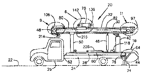
FIG. 1 is a side view of a portable drilling rig constructed in acrordance
with a preferred
I 5 c:mbodimcnt of the present invention, shown xx~ouz~ted on a truck bed.
F1G. 2 is a side view of the portable drilling rig of FIG. 1 showing the rear
end of the rig
raised by jacks and a roller placed between the rig and the truck bed to
facilitate the truck
driving partially out from under the rig.
FIG. 3 is a side view of the portable drilling rig of FIG. 2 shovving the rig
removed from
the truck and the fionx end of the rig resting oz~ a stand.
CA 02452087 2003-12-03
11
FIG. 4 is a side view of the portable drilling rig of'~I~. 1 Shown with the
mast raised t4 a
vertical position and the swivel shown in throE~diffcrent alternate positions.
FIG. ~ is a side vices of the portable drilling rig of FlCx. 4 sl~owz~ with
the zz~ast raised to
an inclined position so that and tin angled bore can be drilled into the
ground.
FIG. 6 is an enlargod side view of the swivel located within circle 6 ofFIG.
1.
FIG. 7 is a cross sectional view taken slang line 7--7 of FIG. ~6,
FIG. 8 is a top view taken alon ; lint 8--8 of FIG. b.
FTG. 9 is an enlarged side view of the upper end of the mast locatod withitr
circle 9 of
FIG. l, shown with the boom tine arm swiveled outward at a :right angle from
the mast.
FIG. 10 is a bottom view of the boom tine arm of FIG. 9 shouting two different
positions
for the boom line arm.
2Q F1G. 1 l is an enlarged side view of the lower end of the mast located
within circle 11 of
FIG. 1.
CA 02452087 2003-12-03
12
F1G. 12 is a top view of the lower end of the mast ofFIG. 11.
FIG. 13 is an end view of the lower portion of the mast of FIG. 11.
F1G. 14 is an enlargod cross sectional view of the guide plt~te for angled
drilling taken
along line 14--14 of FIG. 5.
FIG. 1 S is a side view of the guide plate for angled drilling taken along
line 15--1 S of
FIG. 14.
1~
FIG. 1 b is an enlarged side view of base plate of the drilling rig included
within circle 1 G
of FIG. 1.
FIG. 17 is a top view of the base plate of FIG. 16, taken along line 17....17.
FTG. 18 is a backup wrench that is used in association with the base plate of
PIGS. I 6 and
17 to break pipe loose from the drill sting.
FIG. l 9 is a cross sectional view of the backup wrench of F'IG. 18 taken
along line 19--
~a 19.
FIG. 20 is a removable guide shoe for a drill pipe used in assoc,-iation with
the base plate
CA 02452087 2003-12-03
13
of FIGS. 16 and 17 when the dri11i1ig rig is used to drill a vertical bore
into the gourd.
FIG. 21 is a top view of the removable guide shoe of FICr. 20 showing the
guide plate
altezxxately in an open position and in a closed position.
FIG. 22 is a partially cut away view of the swivel of FIG. 8.
.FIG. 23 is a perspective view of the supporting framework f~~r the drilling
ri$ of FIG. 1.
DETAILED DESCRII'fION OF THE PREFERRED EMB~?DIMENT
INVENTION
~.~ferring raw to the drawings and initially to FYCr. 1, there is illustrated
a portable
drilling xag 20 for drilling water wells or installing geothermal pipe systems
in the ground
22. As illustrated in )1IGS. 1, 2, and 3, the portable drilling rig 20 is
removably mounted
on a bed 24 of a truck 26 via a supporting frame 28 that holds the rig 20 on
the truck bed
24. 'x'he rig 2p is provided with a pivotal single 1 beam mast :f Q that can
be givoted
downward to a horizontal position 32, as illustrated in F!C'x. 1, for
transport and can be
pivoted upward to a vertical position 34, as illustrated in FIG. 4, to drill a
vertical bore 35
into the ground 22, or alternats~ly, pivoted upward to a slanteci or off
vertical position 38
for drilling an angled bore 40 into the ground 22, as illustrated im FICx. ~.
CA 02452087 2003-12-03
14
f1s illustrated in F1G. 5, the mast 30 is pivotally secured to an upwardly
extending,
supporting pivot leg 42 provided secured. to the frame 28 at a. rear end 44.
of the drilling
rig 20. The mast 30 is xaised and lowrered by a first hydraulic cylinder 46
that causes the
S mast 30 to pivot at the supporting pivot leg 42. When the mast 30 is pivoted
downward to
its k~arizontal position 32, an upper end 48 ofthe zz~ast 30 is supported by
an upwardly
extending, front support leg 50 secured to the frame 28 at the front end 52 of
the rig 20.
Referring now to Fl~. 23, bo~t~, the support pivot leg 42 and the front
support leg 50 are
secured in their upright positions by braces 54 that attach on one end 56 of
the brace 54 to
one of the legs 42 or SO and that extend downward a~,td attach at an at~le on
an opposite
end 5$ of the brace 54 to ono of the bottom xxzerr~bers 60 of the frame 28,
thus farming
triangular bracing with the bottom members ~0 of the frame 28 for the legs 42
and 50.
Also the botto~ao. rraembers 60 of the frame 28 attach to a double I-beam 62
of the flame
28 at the rear end 44 of tl~e rig 20 to form triangular configurations witlx
the double Z-
beam 62. The triangular configurations of the bottom me~brxs 60 and the braces
54 of
the frame 28 make it strong.
As illustrated in FIGS. lb and 17, a base plate 64. is securod to the double 1-
beam G2
2Q provided an the frame 28 at the rear end 44 so that the base plate 64
extends horizontally
away from the frame 28. The base plate 64 has a rectang<zlar bit breaker
openix~ 6~
thcrethmugh and a removable plate 68 that attaches over the base pløte 64 via
bolts 70.
CA 02452087 2003-12-03
The base plate 64 is also provided with an upwardly fau'iag "c"-shaped bracket
71 for
holding a wrench or other tool to prevent the wrench or tool from rotating
when torque is
applied to the wrench or tool. The movable plate 6$ has a circular shoe
opening 72
extending through it. The function of the base plate fi4 rind the removable
plate G8 will be
d15Ct1S5ed more fully hereafter.
Also, as illustrated in FIGS. 3 and 4, and 5, jacks 74 atta4h to a lower side
7~6 of the
double I-beam 62. The jacks ?4 can be lowered to the groundl 72 to help
support the
frame 28 above the ground 22 either when the rig 20 is being used for drilling
or when
10 the rig 20 i5 removed from the truck bed 24. The jacks 74 can be retracted
upward towed
the frame 28 when the rig 20 is being transported so that thcy~ do not drag on
the ground
22.
Referring now to FIGS. G, 7 and 8, a swivel 78 is movably attacJhed to a back
side 80 of
15 the mast 30 via a pair ofmast chains 82 so that the swivel 78 can be moved
upward on
the mast 30 and lowered dor~mward on the mast 30 when the mast 30 is raised
from its
horiwntal position 32. One $nd 84 of each of the mast chains 82 secures to a
top 86 of a
non-pivoting portion 88 of the swivel 78 and the other end 90 of each of the
mast cktains
82 secures to a bottom 92 of the non pivoting portion 88 of the swivel 78.
Each of the
mast chains 82 extends over a mast chain sprocket 94 at the upper end ~t8 a~~e
~oaa.st 30,
and as illustrated is FIG'S. 11, 12, and 13, each of the mast chains 82
extends around a
mast drive sprocket 96 at the lower end 97 of the mast 30. The mast chain
sprockets 94
CA 02452087 2003-12-03
provided at the upper end 48 ofthe mast 30 secure to the mast 30 via a
conxmton shaft 9$,
and the mast drive sprockets 96 at the lower end 97 of the xuast 30 secure to
the mast 30
via a cornrnon shaft 100. A pair of mast chain drive motors 1 U2 provi ded on
the lower
end of the zxxast 30 mtate the mast drive slrrockets 95 via a pair of mast
motor drive
chains 104, thereby raising and lowering the swvivel 78.
As shown in FIGS. 9 and 10, a boom line arm 106 is also pivotally secured to
the xzxast 30
on the upper end 48 of the mast 30. The boom line arm 106 pivots so that it
assumes a
non-extended position 10$ where the boom line arm 106 lies horizontal when the
mast 30
is in its horizontal position 32. Also, the boom line ann 106 can be pivoted
to as
extendod position 110 so that the boom line arm 106 extends outward from the
rear end
44 of the rig 20 when the mast 30 is raised from its horizontal position 32.
The boom line
arm 1 U5 is provided with a pulley 112 around which a booms treble 114 runs.
The boom
cable 114 attache.,s on one end 1.16 to a hydraulic winch 11$ provided
attached. to the
frame 28 and attaches on an opposite end 120 to an eye 121 provided on the
swivel 78.
The winch 1 I8 is activated to pivot the swivel 78 by raising the swivel 78 to
a non-
parallel position 122 where the swivel 7$ is non-parallel with. the mast 30,
and
alternately, to lower the swivel 78 back to its original parallel position 12~
so that it is
parallel with the mast 30. It is necessary to pivot the swivel 71i upward out
ofpara11e1
2U alignment with the mast 30 in order to add pipe segments 126 to a bottom
end 12$ of the
swivel 78 when making up a pipe drill string ).30 during Arillung operations
and also to
remove pipe segments 12b $rorn the bottom end 128 of the swivel 78 when
pulling and
CA 02452087 2003-12-03
7
dismantling a pipe drill string 130.
lt.efernng now to FIGS. 6, 7, and $, the swivel 7$ is pz~ovided with dual
swivel drive
sprockets 132 at its top end l 34. The dual swivel drive sprockets 1.32 are
secured to a
drive shaft 136 via a key 13$ that fits into keyways 140 and 141 provided
respectively in
tl~e drive shaft 136 and in the swivel drive sprockets 132. The; drive shaft
136 extends
from the top end 134 of the swivel 78, through the swivel 78, and. to the
bottom end 128
of the swivel 78. Twv swivel drive motors 142 are secured to the top end 134
of the
swivel 78. The dual swivel drive sprockets 132 are driven by the two swivel
drive motors
i 0 142 via a pair of swivel drive chaizts 144. Each of the swivel drive
chains 144 engage its
associated swivel drive sprocket 132 az~d a drive motar sprocket 146 provided
on its
assaciated swivel drive motor 142 to cause the drive shai3 136 to rotate
within the swivel
78 when the rig 20 is being used to drill.
Referring also to F1G. 22, the swivel 78 is provided with bearings I48 located
adjacent to
the dual swivel drive sprockets 132, and the drive sham 136 rotates within the
bearings
14$. The bearings 148 attach to a supporting collar 150 that secures to a
pivoting member
152. A main body 1 S4 of the swivel 78 also attaches via a support arm 156 to
the
pivoting member 152 to hold the swivel 78 stationary relative to the pivating
member
152. The pivoting member 152 pivotally attaches via a pivot rod 158 to the non-
pivoting
portion 88 of the swivel 78.
CA 02452087 2003-12-03
I$
The pivoting member 152 and the attached swivel 78, as a unfit, pivot at the
pivot rod 15$
to rnovc the swivel 78 from its non-parallel pas'ition 122 where the swivel 78
is out oi'
para11e1 alignment with the mast 30, and alternately, back into its parallel
position 124
where the swivel 78 is in parallel alignment with the mast 30, as previously
described.
The bearings 148 arc retained on the drive shaft 136 by a shoulder 160
provided an the
drive shaft X36 at a lower end 162 ofthe collar 150 and by a threaded nut 164
on the
other upper end 166 of the col lar 150. The threaded nut 164 engages threads
166
lrrovid.cd on the drive shaft 136 on a portion of the drive shaft 136 located
adjacent to the
dual swivel drive sprockets 132.
'.l"he drive shaft 136 extends through a main body 154 of the swivel 78 that
is located
adj acez~t to the Supporting collar 150 and bearings 148. The main body 154 is
comprised
of a hollow central cylinder 170 to v~hich an end flange 172 at~taehes at
either end 174
and 176 of the central cylinder 174 via lock bolts 178. 'The end flanges 172
fit tightly
t 5 within the central cylinder I 70 and an. o-xing 180 provided in .an o-ring
groove 182 in
each of the end flanges 172 prevents drilling fluid (not illustrated) from
exiting the
hollow central cylinder 170 by preventing the fluid from travelling between
the end
flange 172 and the hollow central cylinder 170 wltere they join together.
Each end flange 172 has a drive shaft opening 184 in it and through which the
drive shaft
136 extends. Several gland packing rings 186 are provided internally in the
main body
154 adjacent to each of the end flanges 172. A brass ring 188 :is provided adj
acent to each
CA 02452087 2003-12-03
19
set of gland packing rings 186. Each brass ring 188 secures to~ the drive
shaft 136 via
screws 190 so that the gland packing rings 1$6 are sandwiched between their
end flange
I72 and their associated brass ring 188. Distance between a brass ring 188 and
its
associated end flange 172 can be decxe-used by tightening the lock bolts 178
in order to
compress the gland packing rings 186 so that they tighten around the drive
shall 136. The
gland packing rings 1.85 prevent drilling fluid from exiting the main body 154
via the
drive shaft openings 184 in tlae end flanges 172.
The central cylinder 170 is provided with a fluid inlet opening 192 for
admitting drilling
fluid into the hollow rnain body 154 of the swivel 7$. The drive shaft 136 is
provided
with sevexal fluid openings 194 that communicate thmugh thE; drave shaft 136.
The fluid
openings I94 are provided in a portion of the drive shaft 136 'that is located
within the
hallow main. body 1 ~4 of the swivel 78. Each of these fluid openings 194
extends thxough
the drive shaft 136 into a hollow segnent 196 ai the drive shaft l3ti. The
hollow segment
16 196 of the drive shaft 13d is continuous with the lower end 1518 of the
drive shaft 136 so
that the drive shaft 136 is hollow as it terminates at the bottom end 128 of
the swivel 78.
The Lower end 198 of the drive shaft 136 is provided with zmale threads 200
for
removable engagement with mating female threads (not illustrated) provided on
pipe
segments 126. Thus, drilling fluid flows into the hollow main body of the
swivel 78 via
the inlet opening 192, then into the hollow segment 196 of the: drive shaft
136 via the
fluid openings 194 in the drive shaft 13d, and from there into the hollow
interior of the
pipe segments 126 comprising tiae pipe drill string 130.
CA 02452087 2003-12-03
As shown in FlCx. 5, when tlxe drilling rig 20 is placed in a sla;uted
position 3 $ so that it
can be used td drill an angled bore 40 into the ground 22, a guide plate 202
is removably
secured to a lowez~ end 9? of the mast 30. As illustrated in F1GS. 14 and I S,
the guide
5 plate 202 opens up so that it can extend around the pipe drill string 130 to
help support
the pipe drill string 130 and to hold it atthe proper angle "A" relative to
the groruxd 22
when drilling an angled bore 40.
When the drilling rig 24 is placed in its vertical position 34 so that it can
be used to drill a
t 0 vertical bare 36 into the ground 22, a specially designed guide shoe 204
is placed around
the pipe drib string 130. As showzx in FIGfS. 20 and 21, two halves of the
guide shoe 204
swing opens to Facilitate attaching and rem~ovi~~g it from the pipe drill
string 130. As
illustrated in FICIS. 20 and 21, the guide shoe 204 has a downwardly extending
lip 206
that inserts within the shoe opening 72 provided in the base plate 64, thus
allowing the
15 base plate 64 to help keep the pipe drill stx~ 130 in approxirraately
vertically alignzz~ent
during drilling. As shown ua vIC~S. l6 and I 7, the shoe opening 72 is
provided in a
removable plate 68 attached via bolts ?0 to the base plate 64. The removable
plate 6g can
be removed to reveal a bit breaker opc~ing 66, as will be discussed hereafter.
20 Pipe segments 126 of the pipe drill string 130 must be broken apart from
each other to
either add pipe segments 12G to the pipe drill string 130 or to remove pipe
segments T26
from the pipe drill string 130. Ira order to break the pipe segments I2G
apart, the guide
CA 02452087 2003-12-03
21
shoe 204 is first removed from the pipe drill string 130. Next, a specially
designed
backup wrench 208 is inserted around the pipe segment 125 so that the u-shaped
head
210 of the backup wrench 208 engages a llat portion {not illustrated} provided
on each
end of the pipe segnent 126. The backup wrench is illusiated in FIGS. 18 and
19. The
backup backup wrench 2Q$ is provided with au upwardly extending loop shaped
hazxdle
211 for ease in lifting the backup wrench 208. A downwardly extending lip 212
provided
on the specially designed backup wrench 2(?$ is next inserted. into the shoe
opening 72 in
the hase plate 54.
Then a tradzkioz~al pipe-breaking wrench {not illustrated} is ex~nployed to
grasp a pvrkion
(not i11u5trated} an the end of the adjacent pipe segnent 12d. In order for
the operator to
handle a heavy traditional pipe-breaking wrench (not illtastrated), a pulley
214 is providod
on the ftbnt side 216 of the mast 30 and a wrench cable 218 runs through the
pulley 214.
One end 220 of the wrench cable 21$ removably attaches to the winch 118 that
is
attached to the fiarne 28 and an opposite second ez~d 222 of the wrench cable
218
removably attaches to the traditional pipe breaking wrench {not illustxated}
to assist tlae
operator in lifting, positiox~iz~g and holding the heavy pipe-bre;alcing
wrench (not
illustrated}.
As illustrated in FIG. 4, a cable 224 that rtttaches on a first end 226 to a
second hydraulic
cylinder 228 can be attached on its second end 230 to the traditional pipe-
breaking
wrench {not illustrated) in order to provide the neoessary torque to break the
pipe
CA 02452087 2003-12-03
z2
segments 126 apart so that they can be unthreaded fmrn eac h other.
When it is necessary to remove a drilling bit (not illustrated) firom the pipe
drill string
130, the removable glaze 68 is removed from the base plate 64 to reveal the
bit breaker
opening 64 provided xz~ tire base plate 64. The bit brcralccr opening 66 is
employed for
holding a bit breaker tool (not illustrated). The bit breaker tool (not
illustrated) is used to
hold the drilling bit (not illustrated) so that it does not u-o~te relative to
the base glate b4.
'this is necessary when the drilling bit (not illustrated) is disengaged
fCaxx~ khe pipe drill
string x 30 by employing a method sir~ailar to the anc described above for
separating pipe
segments 126.
Although the invention has been described as being hydraulic powered and using
chain
drirres and sprockets, the invention is not so lizx~ited. Other types of
pourer can be used to
drive the drilling rig 20 and p~lanetaty drive hydraulic orator or motors may
be used
iuxstead of the hydral~lic motors that have been described.
While the invention has been described with. a certain degree of
particularity, it is
xaanifest that marry changes may be made in the details of construction and
the
arrangement of components without departing tiram the spirit and scope of this
ZO disclosure. It is understood that the invention is not limited to the
ex~abodiments set forth
herein for the purposes of exelnpli~cation, but is to be limited only by the
scope of the
CA 02452087 2003-12-03
23
attached claim or claims, including the full range ofeqnivalency to which each
clement
thereof is entitled.