Note : Les descriptions sont présentées dans la langue officielle dans laquelle elles ont été soumises.
CA 02452267 2003-12-29
WO 03/003591 PCT/US02/20149
TRANSMITTER CIRCUIT ARCHITECTURE FOR REDUCING
IN-BAND NOISE IN POINT TO MULTIPOINT COMMUNICATION
BACKGROUND OF THE INVENTION
Typical prior art point to multipoint communication systems comprising a base
station and plural remote stations typically adjust the gain of the
transmitter on each
remote station to the same value. The value for transmitter gain is typically
based on the
distance of the furthest remote from the base station, i.e., the highest gain
value, so that
the base station is ensured to be able to communicate with the furthest
remote. Setting
transmitter gain to an identical value for all remote stations in a
communication system is
common practice for prior art broadband wireless access systems. Such a prior
art
transmitter gain scheme allows for communications between the furthest remote
and the
base station without having to modify individual transmitters when the remote
station
transmitters are placed in the field. While this scheme allows for commonality
between
all the remote station transmitters in the communication system, the scheme
results in a
poor inband noise figure for the receiver at the base station thereby limiting
the number
of remote stations that can communicate with the base station.
One embodiment of the present invention avoids the problems of the prior art
by
the use of a novel wireless point to multipoint communication system which
maximizes
the number of remote stations capable of communicating with a base station.
The present
invention allows for more remote stations by minimizing the inband noise floor
of the
base station receiver.
The inband noise floor of the base station receiver is affected by, among
other
things, the strength of the signals in the frequency band of interest received
from the
remote stations with which the base station communicates. Prior art systems
adjust the
CA 02452267 2003-12-29
WO 03/003591 PCT/US02/20149
gain of the remote station transmitters to be the same value regardless of the
distance
between an individual remote station and the base station. The gain is
typically set at a
value to allow the remote station that is furthest from the base station to be
able to
communicate with the base station, which results in a gain setting for the
other remote
stations that are closer to the base station than the furthest remote station
to have a
transmitter gain setting that is higher then necessary to communicate with the
base
station. The higher gain setting for the closer-in remote stations results in
an "excess
inband signal strength" seen by the receiver at the base station from the
closer-in remote
stations. The excess inband signal strength causes the inband noise floor of
the base
station receiver to increase. This increase in the inband noise floor
effectively limits the
number of remote stations with which the base station can communicate.
The present invention discloses a system and method for independent gain
control
of the transmitter on a particular remote station as a function of the
distance between that
remote station and the base station. Independent gain control eliminates the
excess
inband signal strength thereby allowing for an increase in the number of
remote stations
with which the base station can communicate. One embodiment of the present
invention
accomplishes gain control of the remote station transmitters by including
attenuators in
the RF transmit circuit of the remote stations. Any number of attenuators may
be added
to the RF transmit circuit as contemplated by the present invention. The
attenuators may
be placed anywhere in the RF transmit circuit but preferentially are placed
immediately
preceding the RF power amplifier in the RF transmit circuit. The amount of
attenuation
2
CA 02452267 2003-12-29
WO 03/003591 PCT/US02/20149
that the attenuators may add to the RF transmit circuit may be variable and
may be
controlled by a microprocessor. In one embodiment of the present invention, a
value
representing the amount of attenuation to be applied to a remote station
transmitter is
input into a look up table at the remote station. A microprocessor at the
remote station
accesses the value in the look up table and sends a control signal to an
attenuator in the
RF signal path of the remote station transmitter to control the amount of
attenuation that
the attenuator adds to the RF signal path. Therefore, the amount of
attenuation added to
the RF signal path'is a function of the distance between the remote station
and the base
station.
Accordingly, it is an object of the present invention to provide a novel
wireless
point to multipoint communication system where ones of plural remote stations
utilize
transmitter gain control.
It is another object of the present invention to provide a novel wireless
point to
multipoint communication system where ones of plural remote stations utilize
transmitter
gain control as a function of the distance of the remote to the base station.
It is yet another object of the present invention to provide a novel wireless
point to
multipoint communication system where gain control of the remote stations is
achieved
by placing high frequency attenuators in the RF transmit path.
It is still another object of the present invention to provide a novel RF
transmission
circuit where controllable attenuators are placed in the RF transmit path
immediately
preceding the RF amplifiers.
3
CA 02452267 2003-12-29
WO 03/003591 PCT/US02/20149
It is a further object of the present invention to provide a novel RF
transmission
circuit where a microprocessor controls the amount of attenuation of
attenuators placed in
the RF transmit path.
It is yet a further object of the present invention to provide awovel wireless
point
to multipoint communication system for millimeter wave communication signals
where
ones of plural remote stations utilize transmitter gain control.
It is still a further object of the present invention to provide a novel
wireless point
to multipoint communication system for transmitting communication signals in
the 3.4 to
3.7 GHz frequency range where ones of plural remote stations utilize
transmitter gain
control as a function of the distance of the remote to the base station.
It is an additional object of the present invention to provide a novel
wireless point
to multipoint communication system for millimeter wave communication signals
where
ones of plural remote stations utilize transmitter gain control to maximize
the number of
remote stations that can communicate with a base station.
It is yet an additional object of the present invention to provide a novel
wireless
point to multipoint communication system for millimeter wave communication
signals
where ones of plural remote stations utilize transmitter gain control to
maximize the
number of remote stations that can communicate with a base station by
minimizing the
noise floor of the receiver at the base station.
It is still an additional object of the present invention to provide a novel
wireless
point to multipoint communication system where ones of plural remote stations
utilize
4
CA 02452267 2003-12-29
WO 03/003591 PCT/US02/20149
transmitter gain control as a function of the distance of the remote to the
base station
where the gain control of the transmitter of each remote station can be
adjusted
independently of the gain control of the transmitter of other remote stations.
These and many other objects and advantages of the present invention will be
readily apparent to one skilled in the art to which the invention pertains
from a perusal of
the claims, the appended drawings, and the following detailed description of
the preferred
embodiments .
BRIEF DESCRIPTION OF THE DRAWINGS
Figure 1 is a depiction of a wireless point to multipoint communication system
with a single base station and plural remote stations in which the present
invention may
be used.
Figure 2 is a functional block diagram of the transmitter circuit for a remote
station indicating the location of the attenuators immediately prior to the RF
amplifiers
and controlled by a microprocessor according to the present invention.
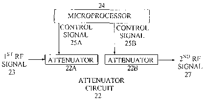
Figure 2A is a function block diagram of the attenuator circuit of Figure 2
according to one embodiment of the present invention.
Figure 3 is a graphical display showing a decrease of inband noise as a
function of
the attenuation setting on a set of two attenuators according to the
embodiment of the
present invention in Figure 2A.
CA 02452267 2003-12-29
WO 03/003591 PCT/US02/20149
DESCRIPTION OF PREFERRED EMBODIMENTS
With reference to Figure 1, a depiction of a typical wireless point to
multipoint
communication system with a single base station and plural remote stations is
shown.
The base station 10 communicates via a wireless communication link with each
of the
remote stations 11, 12, 13, and 14. It is to be understood that while only
four remote
stations are shown in Figure l, the invention is not necessarily limited to a
communication system with only four remote stations. A communication system in
accordance with the present invention comprising more than four remote
stations is
contemplated. The number of remote stations that can communicate with the base
station
is a function of, among other things, the inband noise floor of the receiver
at the base
station. The present invention minimizes the inband noise floor to allow a
maximum
number of remote stations to communicate with the base station as described
below.
The base station 10 includes a transmitter for transmitting a communication
signal
to one or more of the remote stations, and a receiver for receiving
communication signals
from the remote stations. Each of the remote stations l I, 12, 13, and 14
include a
receiver for receiving a communication signal transmitted by the base station,
and a
transmitter for transmitting a communication signal to the base station. The
remote
station transmitters each include an RF txansmit circuit, known as an RF
transmit path,
which increases the frequency of an intermediate frequency communication
signal to RF
frequencies, amplifies the RF communication signal, and transmits the RF
communication signal. The RF amplifiers in the RF transmit path amplify the RF
6
CA 02452267 2003-12-29
WO 03/003591 PCT/US02/20149
communication signal. The RF communication signal can be any type of
communication
signal which is known to one of skill in the art, such as, but not limited to,
code division
multiple access ("CDMA"), time division multiple access ("TDMA"), or time
division
multiplexed ("TDM"). The type of information in the communication signal can
be of
any type, such as, but not limited to, data, voice, video, multimedia, or any
combination
thereof.
Prior art communication systems and broadband wireless access systems
typically
set the amount of gain for the RF transmitter in each remote station based on
the distance
between the furthest remote station and the base station. In Figure 1, the
gain for the RF
transmitter in the remote stations 11, 12, and 13, according to the prior art,
would be the
same as the gain for the RF transmitter in the remote station 14, even though
the gain for
the RF transmitter in the remote stations 1 l, 12, and 13 may not necessarily
need to be set
as high as the gain for the RF transmitter in the remote station 14.
With reference to Figure 2, the RF transmit path for a remote station
transmitter, in
accordance with an embodiment of the present invention, is depicted in a
functional block
diagram. The intermediate frequency ("IF") signal 21 is input into the first
RF circuit 20
which produces the first radio frequency ("RF") signal 23. The IF signal 21
may contain
any type of digitized data such as, but not limited to, data, voice, video,
multimedia, or
any combination thereof. The first RF signal 23 is typically a representation
of the IF
signal 21, including the data encoded in the signal, but the RF signal is at a
higher
frequency. The first RF circuit 20 may contain any combination of oscillators,
filters,
7
CA 02452267 2003-12-29
WO 03/003591 PCT/US02/20149
buffers, synthesizers, mixers, and other components as would appear in any
circuit
known in the art to transform an IF signal in a radio transmitter to an RF
signal. The first
RF signal 23 is input into the attenuator circuit 22. The attenuator circuit
may contain
one or more attenuators. The attenuator circuit also includes standard means
for
adjusting the amount of attenuation of the attenuators. The control signal 25
is provided
by the microprocessor 24 and the control signal 25 is also input into the
attenuator circuit
22. The look up table 26 may contain information representative of the
distance between
the remote station and a base station with which the remote station
communicates via a
wireless radio link. The lookup table is operatively connected to the
microprocessor. In
one embodiment of the present invention, the microprocessor 24 provides a
control signal
to the attenuator circuit 22 as a function of the information contained in the
lookup table
26. The attenuator circuit 22 produces the second RF signal 27 which is
provided to the
second RF circuit 28. In one embodiment of the present invention, the
attenuators are
placed in the later stages of the transmit path in order to maximize the
benefit of the
attenuation of the RF signal being processed through the transmit path. The
benefit of the
attenuation is maximized since the gain after the attenuators cannot be
reduced. The
second RF circuit may contain one or more RF amplifiers 30 and an antenna 32.
The
antenna is typically directional and pointed towards the base station with
which the
remote station communicates. It is to be understood that any type of antenna
will work
with the present invention. The second RF circuit 28 amplifies the second RF
signal 27
and antenna 32 transmits the RF communication signal 29.
8
CA 02452267 2003-12-29
WO 03/003591 PCT/US02/20149
With continued reference to Figure 2, the operation of the depicted remote
station
RF transmitter is as follows. The IF signal 21 is provided to the first RF
circuit 20 which
produces a first RF signal 23. The IF signal, in one embodiment of the present
invention,
is in the range of 40 - 48 MHz and is preferably 44 MHz. The first RF signal
is typically
a higher frequency representation of the IF signal and is in the range of 3.4 -
3.7 GHz and
is preferably 3.5 GHz. The first RF signal 23 is provided to the attenuator
circuit 22
which produces the second RF signal 27 responsive to the first RF signal 23
and the
control signal 25. The frequency of the second RF signal is approximately the
same as
the frequency of the first RF signal. The microprocessor 24 retrieves
information related
to the distance from the remote station to the base station from the lookup
table 26. The
distance information in the lookup table is typically entered into the lookup
table at or
about the time the remote station is physically put in place, although the
distance
information in the lookup table may be entered at any time. Generally, the
distance
information is entered into the lookup table prior to the initiation of the
transmission
sequence being now described. The microprocessor provides a control signal 25
to the
attenuator circuit 22 as a function of the distance information in the lookup
table 26.
Therefore, at least one attribute of the control signal 25 is a function of
the distance of the
remote station to the base station. As described above, the attenuator circuit
22 includes
at least one attenuator where the amount of attenuation of one or more of the
at Ieast one
attenuators is adjustable in response to the control signal 25. Therefore, the
amount of
attenuation added by the attenuator circuit 22 is controlled by the
microprocessor 24 via
9
CA 02452267 2003-12-29
WO 03/003591 PCT/US02/20149
the control signal 25 as a function of the distance between the remote station
and the base
station.
By controlling the amount of attenuation added to the RF transmit path, the
inband
noise level performance of the base station transmitter is improved (see
Figure 3 as
discussed below) which has the effect of increasing the performance of the
base station
receiver thereby allowing for more remote stations to communicate with the
base station.
The present invention allows the transmitter of each remote station of a
communication
system to be individually adjusted so that the gain of the transmitted RF
communication
signal is sufficiently high for reliable communication with the base station
yet not too
high to result in a poor inband noise figure and thereby degrade the
performance of the
base station receiver. For example, for the remote station 12 of Figure 1,
which is closer
to the base station 10 than the remote station 14, the amount of attenuation
to be added to
the transmitter for the remote station 12 will be more than the amount of
attenuation to be
added to the transmitter of the remote station 14.
Still with continued reference to Figure 2, the second RF signal 27 is
provided to
the second RF circuit 28. The second RF circuit may contain at least one RF
amplifier 30
and an antenna 32. The second RF circuit produces and transmits, in response
to the
second RF signal 27, the RF communication signal 29. The RF communication
signal 29
is approximately the same frequency as the second RF signal 27 and is a higher
frequency representation of the IF signal 21, including the data encoded
within the IF
signal, as is standard in the art.
CA 02452267 2003-12-29
WO 03/003591 PCT/US02/20149
With reference now to Figure 2A where like components have like numbers, the
attenuator circuit 22 is shown in functional block diagram format with the
respective
input and output signals. In this embodiment the attenuator circuit 22
includes two
attenuators, the attenuator 22A and the attenuator 22B, where the amount of
attenuation
of the attenuators is responsive to the control signal 25A and the control
signal 25B,
respectively, as described above. The microprocessor 24 provides the control
signals
25A and 25B which may be the same or different.
With reference now to Figure 3, the graphical display shows the inband noise
performance of a remote station transmitter for various attenuator settings.
For Figure 3,
the attenuator circuit 22 includes two attenuators, the attenuator 22A and the
attenuator
22B, as shown in Figure 2A. The vertical axis of Figure 3 is an inband noise
parameter
measured in decibel-milliwatts per hertz (dBm/Hz). The horizontal axis of
Figure 3 is the
attenuation added by the attenuators in decibels (dB). The upper curve on the
graph is
representative of the effect on the inband noise parameter due to the
attenuation setting of
the attenuator 22A. The lower curve on the graph is representative of the
effect on the
inband noise parameter due to the attenuation setting of attenuator 22B. It
should be
noted that as the attenuation of either of the attenuators increases (from
left to right on the
horizontal axis) the inband noise parameter decreases (becomes more negative).
By controlling the inband noise parameter individually for each remote station
in a
point to multipoint wireless communication system, the noise floor of the
receiver at the
base station is lowered thereby increasing the performance of the base station
receiver.
11
CA 02452267 2003-12-29
WO 03/003591 PCT/US02/20149
This increase in performance permits more remote stations to communicate with
the base
station.
While preferred embodiments of the present invention have been described, it
is to
be understood that the embodiments described are illustrative only and the
scope of the
invention is to be defined solely by the appended claims when accorded a full
range of
equivalence, many variations and modifications naturally occurring to those of
skill in the
art from a perusal hereof.
12