Note : Les descriptions sont présentées dans la langue officielle dans laquelle elles ont été soumises.
CA 02452776 2003-12-22
WO 03/000474 PCT/CA02/00981
WOOD-GLUING AND CLAMPING SYSTEM AND PRODUCTS
FIELD OF THE INVENTION
The invention relates to a wood gluing and clamping system enabling the
continuous production of edge or face glued pieces of lumber for panels and
the like. The
system includes a deck, a horizontal displacement system for advancing lumber
across the
deck, a braking system, a one-way clamping system and an upstream pressure
system. The
edge-gluing system may be used in conjunction with finger jointing processes
or with
single pieces of lumber and may be used for the production of both furniture
grade and
construction grade wood products to NLGA and NGRC standards.
BACKGROUND OF THE INVENTION
In the lumber industry, it is well known that wood boards can be edge-glued to
create larger panels of wood or face-glued to create beams.
It is also known that the scrap wood from various high-end lumber operations
such
as sawmill operations contain useful quantities of wood fibre which can be
salvaged for
lower-end lumber operations including the production of finger jointed wood
products.
Finger jointing processes cut usable wood fibre from scrap material and
through shaping,
gluing and clamping the ends of the scrap material create longer lengths or
boards of
lumber. The resulting longer boards built up from shorter lengths have
advantages over
equivalent lengths of solid, single piece lumber including 1) they will often
be less
expensive, 2) using certain glues, they will often have structural strengths
equivalent to or
greater than the strengths of an equivalent length of solid, single-piece
lumber and, 3)
longer, stable and straight boards of lumber (typically up to 62 feet) can be
created.
As with solid, single-piece boards, finger jointed boards can, depending on
certification, be utilized as conventional lumber (ie for framing) or can be
edge-glued
and/or face-glued to create other lumber products. In particular, edge-glued
lumber can be
used to create slabs and face-glued lumber can be used to create beams.
Over the years, many techniques for finger jointing have evolved and continue
to
evolve both with respect to materials handling aspects of the process as well
as with the
1
CA 02452776 2003-12-22
WO 03/000474 PCT/CA02/00981
gluing technology. For example, and with respect to gluing technology, in high
speed
operations producing finger jointed lumber, it is desirable that glue set
times are fast in
order to maintain high throughput levels. However, high-speed gluing requires
that a
careful balance be maintained between the glue set time and production speed
to ensure
that the glue sets during the clamping phase of assembly and not too early or
too late in the
process. In particular, a glue setting too early in the process will prevent
proper assembly
of the finger jointed pieces whereas a glue setting too late will require
longer clamping
times. Furthermore, there remains the problem that faster setting adhesives
may set up in
the pot or barrel.
Past glues have included phenol based glues which through a combination of
moisture and heat-activation (microwaves) initiate the glue setting which in
combination
with the joint structure provide the resulting adhesive and structural
strength at the joint.
However, heat-activated glues utilizing microwaves require complex tunnels to
both emit
the microwaves and shield the plant from this radiation. In addition, the
technology
relating to products manufactured from phenol glues lend themselves to batch
processes as
opposed to continuous flow production by virtue of glue-setting apparatus.
This is
particularly true with respect to an edge gluing process.
As a result of some of the problems of phenol glues, quick-setting
polyurethane
glues have been developed and incorporated into high speed finger jointing
operations.
Polyurethane glues require moisture for setting which may have to be
introduced into the
process depending on the moisture content of the wood. Thus, the use of
polyurethane
glues is particularly suited to use with gluing green or wet-wood.
Furthermore,
polyurethane glues do not require the same specialized clamping and setting
equipment as
heat activation systems.
The equipment presently used in the continuous production of single lengths of
lumber initially creates a series of fingers on the ends of each piece of
wood. Glue is
applied to each finger joint and each piece of wood is moved onto a linear
shuttle which
accelerates successive pieces of wood against and into a leading piece of wood
thereby
causing adjacent finger joints on each piece of wood to interlock. 'At the end
of the shuttle
2
CA 02452776 2003-12-22
WO 03/000474 PCT/CA02/00981
run, the assembled pieces are stopped against a first clamping surface,
trimmed to length,
moved sideways out of the shuttle run whereupon a longitudinal clamping
pressure is
applied to fully engage the finger joints. The resulting length of lumber is
released from
the clamp onto a horizontal deck to allow for final curing of the glue. As
successive pieces
of lumber are created, cut to length, moved sideways, clamped and released
onto the
horizontal deck, each piece of lumber is horizontally displaced across the
deck. At the
edge of the deck, each piece is removed for final processing, cleaning and
packaging.
In the past, individual boards of single-piece or finger jointed lumber could
be
subsequently assembled by edge-gluing to create slabs or face-glued to create
beams in
one or more separate operations to the milling or finger jointing processes.
For example, past edge-gluing processes apply glue to the edges of adjacent
boards
and clamp and press adjacent boards together while the glue is curing to form
a slab.
However, such processes are generally non-continuous, slow and/or labour-
intensive
which results in higher production costs than could be achieved if the slab
was created as
part of the initial milling or finger jointing assembly process.
Accordingly, there has been a need for an edge or face gluing process and
apparatus that provides the continuous assembly of lumber into edge-glued or
face-glued
slabs at high speed and pressure.
Another problem with past wood-gluing equipment is the clamping pressure
profile
applied to a growing slab. That is, in past systems which may apply a clamping
pressure
across a growing slab, as each successive board is added to the growing slab,
there are
substantial changes in the clamping pressure as linear shuttles advance and
retreat.
Accordingly, there has been a need for a wood-gluing process and apparatus
which
provides a high, continuous clamping pressure across the width of the slab
while
additional boards are being prepared and added to the slab.
Further still, there is a distinction between panels manufactured for fu
niture and
for construction. In particular, construction grade lumber requires that the
strength of any
3
CA 02452776 2008-03-06
glued joint meets certain design values established for the particular grade
whereas
furniture grade wood does not require the same joint strength or integrity.
For example, in
manufacturing construction grade lumber from glued pieces of wood (either
finger jointed
or edge-glued) using cold-clamping with a polyurethane adhesive, constant high
clamping
pressures are required to ensure maximum joint strength and proper glue
penetration into
the wood during the curing cycle.
Furthermore, in particular jurisdictions, the use of wood for construction
purposes
requires that the lumber meet the standards required under jurisdictional
building codes
such as the Canadian and U.S. building codes. In North America, the Canadian
Lumber
Standards Accreditation Board (CLSAB) and the American Lumber Standard (ALS)
Board of Review, approve and enforce the rules established by the Canadian
National
Lumber Grades Authority (NLGA) and the National Grading Rules Committee (NGRC)
respectively. The Canadian National Lumber Grade Authority (NLGA) conforms to
the
National Grading Rule (NGRC) in its own rules for dimension lumber, with some
exceptions. For example, the NLGA establishes unique design values for fibre
of Canadian
origin. Certification of product under these rules is required to enable the
use of product
by the builders as is required by code officials.
Structural lumber products range in dimensions of width and thickness from 2"
to
4" thick by 2" and wider. The certification grades, from lowest to highest,
progress
through stud grade, #2, #1 and select structural. Standards for each grade are
described in
the manuals of the NLGA, and American rules writing agencies conform to the
Department of Commerce PS 20-99 (American Softwood Lumber Standard) determine
end uses as prescribed by the appropriate building code agency. All rules and
standards
under the NLGA and NGRC as of the date of this document are included in this
application
as Appendix A and Appendix B respectively. Furthermore, while it is understood
that
certification standards may change in the future, the current standards (dated
2002) are the
standards as referenced in this application.
In the past, commercial production of certificated edge-glued structural
lumber has
not been achieved. Accordingly, there has been a further need for cost
effective, high-
4
CA 02452776 2003-12-22
WO 03/000474 PCT/CA02/00981
speed edge-glued and finger jointed structural lumber products, which meet
inter alia
North American Building Code requirements.
More specifically, edge-glued boards manufactured from either solid lumber or
finger jointed boards have not passed the certification standards for
construction grade
lumber and, in particular, commercial production of certification standards
#2, #1 and
select structural have not been achieved. Accordingly, there has been a
further need for
cost effective, high-speed edge-glued and finger jointed structural lumber
products which
meet the certification standards for a range of dimensions.
Past edge-gluing systems have not solved the above problems of manufacture,
quality or commercial viability. A review of the prior art has revealed U.S.
Patent No.
6,025,053 and US Patent 5,888,620 (Grenier) which disclose a process for
adhesively
bonding finger jointed lengths of wood in side-by-side relationship to form
boards; U.S.
Patent No. 4,314,871 (Weinstock) which discloses a method and apparatus for
laminating
timber to form laminated beams; US Patent 4,565,597 (Schulte) which discloses
a method
for producing a veneer web which are bonded side-by-side to form a veneer web;
US
Patent 5,679,191 (Robinson) which discloses a method and apparatus of
fabricating trailer
flooring via an edge-gluing process and US Patents' 3,927,705 (Cromeens),
4,128,119
(Maier), 4,941,521 (Redekop) and 5,617,910 (Hill) which each disclose finger
jointing
apparatus per se.
SUMMARY OF THE INVENTION
The invention solves the above problems by providing a high-speed clamping
system that maintains high horizontal clamping pressure across the width of a
growing
slab while exposing the trailing edge of the growing slab for addition of a
further board. In
addition, the clamping system allows for the horizontal displacement of the
growing slab
away from a shuttle delivering a further board for ultimate removal from the
system.
More specifically, and in accordance with the invention, there is provided an
apparatus for applying a consistent clamping pressure between a plurality of
boards
comprising:
5
CA 02452776 2003-12-22
WO 03/000474 PCT/CA02/00981
a) a deck for supporting a plurality of boards, the deck having an upstream
end and downstream end;
b) a horizontal displacement system operatively connected to the upstream end
for applying a downstream force to the plurality of boards, the horizontal
displacement system operable between a disengaged position allowing a
new board to be positioned adjacent the upstream end and an engaged
position where the plurality of boards is advanced towards the downstream
end;
c) a braking system operatively connected to the downstream end for retarding
advancement of the plurality of boards along the deck when the
downstream force is below a threshold pressure and for allowing
advancement of the plurality of boards if the downstream force exceeds the
threshold pressure, the braking system including an upstream pressure
system for applying a continuous upstream pressure to the plurality of
boards when the horizontal displacement system is moving from the
engaged position to the disengaged position; and,
d) a one-way clamping system operatively connected to the deck for
preventing upstream movement of the plurality of boards when the
horizontal displacement system is moving from the engaged position to the
disengaged position.
In another embodiment, a system for maintaining a high inter joint pressure
across
a plurality of glued boards being continuously assembled on a deck is
provided,
comprising a downstream pressure system, a braking system, an upstream
pressure system
and a clamping system operatively connected to the deck.
In a further embodiment, the invention provides a method of maintaining a high
inter joint pressure between a plurality of boards being assembled into a
panel or beam
comprising the steps of
a) advancing a board across a deck by a horizontal displacement system
through a clamping system restricting the upstream movement of the board;
and
6
CA 02452776 2003-12-22
WO 03/000474 PCT/CA02/00981
b) restricting the downstream movement of the plurality of boards with a
braking system having a threshold pressure, the braking system further
providing an upstream pressure against the clamping system.
In further embodiments of the invention, a structural wood product is provided
comprising a plurality of edge-glued boards wherein the structural wood
product meets
any one of or a combination of NLGA and NGRC standards for No 2 or higher wood
grades and preferably No 1 or select structural standards. In one embodiment
each board
comprises a plurality of forger jointed blocks.
The dimensions of the structural wood product may be standard lumber dimension
products such as 2x6 or 2x8 or custom dimension products
Preferably, the structural wood products includes edge-glued boards that are
cold-
pressed with a polyurethane glue or any certified adhesive meeting ASTM 2559.
DESCRIPTION OF THE DRAWINGS
These and other features of the invention are described with reference to the
drawings wherein:
Figure 1 is a schematic side view of a wood clamping system in accordance with
one embodiment of the invention;
Figure 1 a is a schematic side view of the horizontal displacement system
showing
the engaged and disengaged positions;
Figure 2 is a schematic plan view of the wood clamping system in accordance
with
two embodiments of the invention, the first in conjunction with edge-gluing
single pieces of lumber and the second in conjunction with a finger jointing
process;
Figure 3 is a schematic side view of the braking system in accordance with one
embodiment of the invention;
Figure 4 is a schematic plan view of the braking, the back-pressure and panel
press
systems in accordance with one embodiment of the invention;
7
CA 02452776 2003-12-22
WO 03/000474 PCT/CA02/00981
Figure 4a is a schematic side view of the panel press system and an alternate
embodiment of the clamping system in accordance with different embodiments
of the invention;
Figure 5 is a graph showing inter-board joint pressure as a function of time;
and
Figure 5a is a graph showing inter-board joint pressure as a function of time
in
accordance with an alternate embodiment of the invention.
Figure 6 is a schematic side view of another embodiment of the clamping system
in accordance with another embodiment of the invention:
Figure 7 is data obtained in accordance with testing standards (referred to as
"The
Standard") for the NLGA.
8
CA 02452776 2003-12-22
WO 03/000474 PCT/CA02/00981
DETAILED DESCRIPTION OF THE INVENTION
System Overview
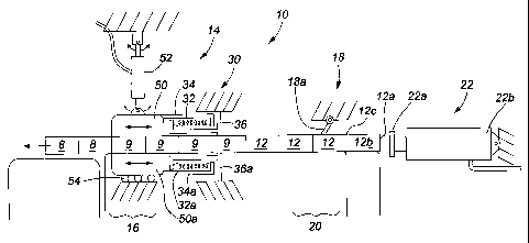
In accordance with the invention and with reference to the figures, a wood
gluing
and clamping system 10 is described which provides a continuous clamping
pressure
across a deck 11 of a growing slab or panel of glued lumber 12. The system 10
generally
includes a deck 11, a braking system 14, an upstream pressure system 30, a
series of one-
way clamps 18 and a horizontal displacement system 22 for forming a panel of
edge-glued
lumber or a beam of face-glued lumber. The following description is written in
the context
of an edge-gluing system although it is understood that the system may be used
in the
same manner for face-gluing.
In operation, a slab or panel of edge-glued boards (shown as panels 8, 9 and
12 in
Figures 1 and 2) is created by successively shuttling a new board 12b past a
glue station 13
to the trailing end 20 of the deck 11 whereupon the horizontal displacement
system (HDS)
22 applies a sideways and translational force to the trailing edge 12a of the
board 12b,
thereby causing board 12b to engage with the edge 12c of a previously
positioned board.
As the new board 12b engages with the previously positioned board, the HDS
meets
resistance and the interface clamping pressure between boards 12 and 12b
increases as the
HDS continues to apply a translational force. The interface clamping pressure
increases
across the deck until each panel 8, 9, 12 is ultimately displaced across the
deck in a step-
wise manner. After the panels 8, 9, 12 are displaced a fixed amount
(typically, the width of
one board), the HDS retracts to an unengaged position to await the arrival of
a new board.
As each panel 8, 9, 12 advances, a high pressure is maintained at each
glue/board
interface by the combination of the braking system 14 and upstream pressure
system 30 at
the leading edge 16 of the slab and a series of one-way clamps 18 which
prevent backward
movement of the slab at the trailing edge 20 of the slab as the HDS moves to
its
unengaged position.
More specifically, as each panel 8, 9, 12 advances across the deck 11, the
upper
and lower surfaces of each panel are engaged by the braking system 14 which
retards the
advancement of the panel 12 along the deck 11 by applying a squeezing pressure
against
9
CA 02452776 2003-12-22
WO 03/000474 PCT/CA02/00981
the upper and lower surfaces of the specific panel (panel 9 in Figures 1 and
2) engaged
with the braking system. The braking system 14 has a threshold pressure which
prevents
movement of the panel 9 through the braking system if the threshold pressure
is not
exceeded but allows the panel 9 to pass through the braking system 14 once the
threshold
pressure is exceeded. Horizontal pressure against the braking system 14 is
provided by the
HDS 22. In the embodiment shown in Figure 1, the braking system 14
frictionally engages
with the upper and lower surfaces of the panel at the upstream end 16 of the
deck 11.
As shown in Figure 1 a, the HDS operates between an unengaged position in
which
it is not making contact with the upstream edge 12a of the slab and an engaged
position in
which it is in contact with the upstream edge 12a of the slab and pushing the
slab 11
through both the braking system 14 and one-way clamps 18.
As pressure from the HDS 22 is released as the HDS moves from the engaged to
the disengaged position, the one-way clamps prevent significant movement of
the slab 12
in an upstream direction. In another embodiment as shown in Figure 6 and
explained in
greater detail below, two hinged blades 90, 90a act as one-way clamps,
reducing
movement of the slab as the HDS moves to the disengaged position.
Importantly, the braking system 14 and upstream pressure system 30, in
addition to
retarding forward motion of the slab, also provides an upstream clamping
pressure against
the panels 9, 12. That is, as the HDS is moving from the unengaged position to
the fully
engaged position and is increasing the displacement pressure, the HDS is
initially
overcoming an upstream pressure from the upstream pressure system 30 and
secondly, is
overcoming the threshold pressure of the braking system 14. As shown, the
upstream
pressure system 30 includes a plurality of springs 32 spaced along the braking
element in
the embodiments shown in Figures 1 and 2. As explained in greater detail
below, Figure 1
shows an embodiment where the upstream pressure system is upstream of the
braking
system 14 and Figure 2 shows an embodiment where the upstream pressure system
is
downstream of the braking system 14.
After the HDS reaches a fully extended position (designated position x as
shown in
Figure la), the HDS reverses direction and returns to the fully disengaged
position
CA 02452776 2003-12-22
WO 03/000474 PCT/CA02/00981
(designated position y in Figure 1 a). The new trailing edge 12a of the slab
12 is prevented
from upstream movement by the one-way clamping system 18 with the upstream
pressure
system maintaining a high joint pressure. As shown in Figure 5, as the HDS
moves to the
disengaged position and the upstream pressure elements apply an upstream force
against
the panel, the joint pressure will decrease slightly but will be maintained
within a high but
narrow pressure range. This is contrasted with the typical joint pressure
profile of the prior
art as also shown in Figure 5. By virtue of the high joint pressure across the
deck, glue
penetration, and hence joint strength makes the subject invention particularly
suitable for
the manufacture of construction grade lumber.
In another embodiment as shown in Figure 6, the one-way clamping system is
actuated from a hydraulic cylinder 52, applying downward pressure on a wedge-
shaped,
fixed plate friction block 95 that meets the upper surface of the panel 12.
The friction
block is preferably a wedge shape in order to more evenly distribute downward
pressure
against the slab in order to reduce damage to the wood and to prevent any
twisting or
rolling of the one-way clamping system. As well, the wedge-shaped block allows
the
knives 90, 90a to penetrate the surface of the panel 12 only to the extent to
which the
knives 90, 90a extend below the block 95.
In a preferred embodiment, two knives 90, 90a are secured to the fixed plate
95
which is pressed into the slab to prevent upstream movement. The knives are
connected to
the fixed plate 95 at pivots 92 allowing the knives 90, 90a to pivot
downstream if the panel
is moving downstream with the knives 90, 90a engaged with the panel so as to
avoid
tearing damage to the panel. Springs 91 bias the knives upstream against
backstop 93 as
contact with the panel is broken to ensure that the knives are vertical as the
clamping
system engages the panel. Two knives are preferably used to minimize the depth
of
penetration of each knife blade required to effectively retard upstream
movement.
As indicated above, the system may be used to create edge-glued panels or face-
glued beams from both single-piece boards and multi-piece finger jointed
boards. It is also
understood that the system be used for both furniture grade and construction
grade
products.
11
CA 02452776 2003-12-22
WO 03/000474 PCT/CA02/00981
Further details and embodiments of the sub-systems are described below:
Horizontal Displacement System
The horizontal displacement system 22 includes a board contacting member 22a
running the length of the deck 11 and positioned at the upstream end of the
deck 11. In
most implementations of the system, the board contacting member will typically
range in
length from 10-62 feet as may be determined by the actual deployment of the
system 10
and the desired end product. Translational actuation of the board contacting
member 22a is
realized by a plurality of hydraulic units 22b operatively connected to the
board contacting
member 22a and to a fixed surface (not shown). The number and spacing of the
hydraulic
units 22b is determined by the performance specifications of each hydraulic
unit and the
desired inter joint pressures. Appropriate hydraulic control of each hydraulic
unit is
provided by an appropriate hydraulic control unit (not shown) to provide
synchronous
actuation of all the hydraulic units 22b. Furthermore, the HDS may include a
rack and
pinion system (not shown) to ensure alignment of the board contacting member
22a along
the length of the deck 11.
Braking and Upstream Pressure System
The braking system 14, as described above, functions to retard the advancement
of
each panel across the deck when the HDS 22 is applying a pressure below the
threshold
pressure and to allow advancement of the panel through the braking system when
the
threshold pressure is exceeded. The upstream pressure system 30 functions to
maintain an
upstream pressure against each panel when the HDS is moving to the fully
disengaged
position and moving to the fully engaged position but below the threshold
pressure.
As shown in Figures 1-4, the braking system includes at least one friction
plate 50
and a hydraulic cylinder 52. The friction plate 50 applies a downward pressure
against the
upper surface of the panel 9 as applied by the hydraulic cylinder 52. In the
embodiment
shown in Figures 1 and 3, a second friction plate 50a is provided on the
underside of the
deck 11.
12
CA 02452776 2003-12-22
WO 03/000474 PCT/CA02/00981
The upstream pressure system 30 includes at least one spring 32 which biases
the
friction plate 50 upstream. As shown in Figure 1, the upstream pressure system
may
include both topside 32 and underside 32a springs. Figure 1 also shows an
embodiment in
which the upstream pressure system is positioned upstream of the friction
plate 50 where
springs 32, 32a are compressible within supporting brackets 34, 34a, 36 and
36a which are
secured to the friction blocks 50, 50a and an immovable surface, respectively.
The
underside friction block 50a is preferably supported on rollers 54 which allow
the friction
block to travel upstream/downstream as required. Hydraulic cylinder 52 may be
pivoted to
allow this travel.
In another embodiment, the upstream pressure system 30 includes hydraulic
cylinders (not shown) to provide the upstream force.
The friction blocks 50, 50a may be any suitable hard-wearing material which
provides sufficient frictional contact with the wood panel to prevent slippage
and maintain
a consistent threshold pressure. Typical friction blocks may be manufactured
from
materials such as square metal tubes or plastic blocks.
As shown in Figure 3 and 4, the friction blocks 50, 50a may also include a
rubber
sleeve 51, 51a which is placed over each block. In this embodiment, the rubber
sleeve may
rotate around the block 50, 50a as each panel is advanced along the deck. The
use of
rubber sleeves reduces the polishing of the friction blocks which may improve
the
consistency of the threshold pressure. In another embodiment, the rubber
sleeves may be
fixed to the block 50, 50a in order that they do not rotate.
As indicated above, the upstream pressure system 30 may be positioned upstream
or downstream of the friction blocks. As depicted in Figures 1 and 3, the
upstream
pressure system is upstream of the braking system. As depicted in Figures 2
and 4, the
upstream pressure system is downstream of the friction blocks.
Furthermore, as shown in Figures 2 and 4, the braking system and upstream
pressure system may include a number of individual elements spaced along the
width of
13
CA 02452776 2003-12-22
WO 03/000474 PCT/CA02/00981
the deck. As shown in Figure 2, a single and continuous friction block 50
extends along
the width of the deck. As shown in Figure 4, rubber sleeves as described above
are
positioned between adjacent hydraulic cylinders 52 around friction block 50.
Other embodiments of the braking system may include systems in which the
friction block is a roller operatively connected to a disc brake having a
threshold pressure
which, once exceeded allows the panel to pass beneath. Still further systems
may include
chains and rollers as understood by those skilled in the art.
One way Clamping System
The one way clamping system 18 includes at least one clamping member or dog
18a (as shown in Figures 1, la, and 2) pivotally connected to an immovable
surface. The
clamping member 18a is angled downstream and pressured to engage the panel 12
such
that if an upstream pressure is applied to the panel, the clamping member
engages the
panel and wedges the panel downwardly and prevent significant upstream
movement. The
wood contacting surface of the clamping member is designed to inflict minimal
damage to
the surface of the panel and, as such, may include a knurled and/or rubberized
wood-
contacting surface 18b as would be understood by one skilled in the art. As
shown in
Figure 2, a plurality of clamping members are distributed along the length of
the deck as
required to provide sufficient holding force from the upstream pressure system
30.
In a further embodiment of the one-way clamping system, the wood contacting
surfaces of the clamping system are automatically actuated to engage with the
panel just
prior to the moment when the HDS 22 begins to move from the fully engaged
position to
the full disengaged position until the threshold pressure is reached on the
next stroke. As
shown in Figure 4a, the one-way clamping system includes a hydraulic cylinder
19 having
a wood contacting member 19a for movement into and against the panel 12. A
back-stop
member 19b prevents backward or upstream movement of the wood contacting
member
19a. Accordingly, as.the HDS 22 moves from the fully disengaged position, y,
until the
threshold pressure is reached and the panel begins to move forward, cylinder
19 is
maintaining a downward pressure on the panel thereby resisting upstream
movement of
the panel by the upstream pressure system 30. As soon as the threshold
pressure is reached
14
CA 02452776 2003-12-22
WO 03/000474 PCT/CA02/00981
by the HDS 22, wood contacting member 19a retracts from engaged position z' to
disengaged position z allowing forward (downstream) movement of the panel 12.
Wood-
contacting member 19a may also be hinged allowing one-way (downstream)
movement of
a panel as described above.
Actuation of the cylinder 19 may be accomplished using position sensors (not
shown) as is known in the art. For example, a position sensor may detect
movement of the
panel (corresponding to' the threshold pressure) to cause the cylinder 19 to
retract to
position z. Similarly, a position sensor may detect board contacting member
22a just prior
to reaching position x and thereafter cause cylinder 19 to advance to position
z'.
In yet a further embodiment of the one-way clamping system (as introduced
above), knife blades 90, 90a are attached to a wedge shaped backplate 95 and
act to retard
upstream movement of the panel 12 when set within the panel 12. The blades are
hinged
on a pivot 92 and attached to a spring 91 allowing some movement of the panel
in the
downstream direction as the HDS begins to advance the slab but prior to the
clamping
system withdrawing. A plurality of knife blade sets are distributed across the
width of the
panel.
20, As shown in Figure 6, the one-way clamping system includes a hydraulic
cylinder
94 having a wedge-shaped wood contacting member 95 for movement into and
against the
panel 12. The wedge-shaped foot 95 allows for more even distribution of
pressure and
therefore reduced damage to the wood. Preferably, the knives 90a, 90a will
penetrate the
wood to a depth of around 1/8 inch with a %2 inch separation between each
knife. A
backstop member 93 prevents backward or upstream movement of the wood
contacting
knives 90, 90a.
Accordingly, as the HDS 22 moves forward from the fully disengaged position,
until the upstream pressure system threshold is overcome and the panel begins
to move
downstream, cylinder 19 is maintaining a downward pressure on the panel
thereby
resisting upstream movement of the panel by the upstream pressure system 30.
As soon as
the upstream pressure threshold is reached by the HDS 22 (or shortly
thereafter), wood
CA 02452776 2003-12-22
WO 03/000474 PCT/CA02/00981
contacting knives 90, 90a retract from the engaged position to the disengaged
position,
allowing forward (downstream) movement of the panel 12. As the clamping system
is
withdrawn, springs 91 retract the knives 90, 90a against backplate 95.
Use of mechanically actuated one-way clamping system will preferably reduce
the
range of inter joint pressures as shown schematically for strokes 2-7 in
Figure 5a.
Panel Press System
In another embodiment of the wood-gluing system, a panel press system 80 is
provided to assist in maintaining a flat panel (Figures 4 and 4a). The panel
press system 80
preferably includes a plurality of rails 82 across the width of the deck.
Transverse to the
rails 82 is a pressure bar 84 for applying a downward force against the rails
82. Downward
force on the pressure bar is provided by at least one hydraulic cylinder 86.
The panel press
system 80 generally provides a downward pressure to the upstream end of the
deck to
minimize joint misalignment between adjacent boards prior to the glue setting
up.
Accordingly, and by virtue of the generally upstream location of the pressure
bar 84, a
greater downward force is provided at the location of the deck where the glue
may be
acting more as a lubricant between boards as opposed to an adhesive.
It is preferred that narrow rails 82 are in contact with the panel surface to
minimize
the surfaces available for contamination by any excess glue seeping from a
joint which
may otherwise over time increase the potential for joint misalignment.
Glue Station
The glue station 13 is located adjacent the linear shuttle 40 and includes
extruding
applicators 13a for applying glue on edge 12a of a board 12b advancing along
the linear
shuttle 40. The glue station 13 has appropriate position sensors and control
system to
apply glue only as a new board is advancing and only as required for a
specific panel
width.
16
CA 02452776 2003-12-22
WO 03/000474 PCT/CA02/00981
System Deployment
The system may be deployed as a stand-alone system either in a single-board or
finger joint edge-gluing system or as a fully integrated component of a finger
jointing
system. In a finger jointing system where it is required that a longitudinal
clamping
pressure be applied to assembled finger jointed blocks, the location of the
one-way
clamping system 18 and control of the HDS may be modified. Specifically, in
order to
allow proper longitudinal clamping pressures to be applied to the finger
jointed boards and
with reference to the elements of Figure 2 in dotted lines, the one-way
clamping system
18' (as shown in dotted lines) is positioned one-board width downstream of the
HDS 22.
Accordingly, after a plurality of loosely finger jointed blocks are shuttled
into position and
the HDS 22 has advanced these blocks onto the deck, a longitudinal clamping
system 19 is
actuated to tightly interconnect the finger jointed blocks. After the
longitudinal clamping
pressure has been applied and released, the next stroke of the HDS advances
the board
through the one-way clamping system 18'. Figure 5a shows a joint pressure
profile for a
combined edge-gluing/finger-joint system. As can be seen, in this embodiment,
a narrow
and high joint pressure is not realized until stroke 2.
The ability to create structural grade lumber using a flat joint is a
particularly
important feature of the invention in view of the advantages realized from a
material
recovery and commercial viability perspective. However, for completeness, in a
further
embodiment, the edges of each block may be shaped upstream to provide
interlocking
between adjacentboards. In this embodiment, appropriate shapers are positioned
upstream
of the glue station 13 to shape one or more edges of boards or pieces and
appropriate
modifications to the HDS may be required.
Adhesives
The adhesives used in the system are preferably adhesives meeting the ASTM
2559 standard including polyurethanes such as Franklin Reatite 8243.
17
CA 02452776 2008-03-06
System Control
The system can be controlled using programmable logic controllers having
timers,
pressure, temperature, flow and position sensors as is known in the art. In
particular,
appropriate control of the glue station will enable panels of different widths
to be prepared.
Furthermore, while this description generally describes an edge-gluing system,
it
is understood that the faces of boards may be glued in a manner described
above. Still
further, edge-glued lumber prepared in accordance with the invention can be
subsequently
face glued for lamination into beams or used in vertical or horizontal
structural
applications.
Examples:
Figure 7 is representative data for 2x8 lumber obtained in accordance with the
Western Wood Products Association (WWPA) (authorized by the National Grading
Rule
Committee (NGRC) to develop and maintain Western lumber grading rules) Glued
Products Procedures and Quality Control C/QC 101. Test results have similarly
been
obtained for 2x6 edge-glued lumber. Samples of 2x8 and 2x6 edge-glued SPF
lumber
met the criteria for grades up to No 1 and No 2 Certified Glued Lumber and
received
approval to be stamped or marked to reflect these qualities.
More specifically, Figure 7 shows the data required to produce, and the
calculated
results, for the Modulus of Rupture "Fb" (MOR), and Modulus of Elasticity "E"
(MOE).
These design values are established and documented by the NLGA in the NLGA
January
1, 2002 Standards Manual Standard Grading Rules for Canadian Lumber ("the
Standard").
Production run structural lumber of varying widths was fabricated in
accordance
with the methodology described above. Inter-joint pressures of greater than
100 psi were
maintained during the manufacturing process. Each lumber piece comprised a
plurality of
interlocked finger jointed blocks forming a single block-width board which was
subsequently edge glued to at least one other single block-width board to form
a length of
structural lumber. Each block included reversible finger joints composed of 7
fingers 5/8"
18
CA 02452776 2003-12-22
WO 03/000474 PCT/CA02/00981
long running parallel to the wide face of the lumber. The polyurethane
adhesive used for
both finger jointing and edge-gluing was Franklin Reatite 8243 (Franklin
International,
Columbus, Ohio).
Edge-glued samples were randomly selected and tested for tension and
delamination. For 2x8 testing, thirty (30) test samples were selected and
tested for tension.
Seven were tested for delamination. Twenty edge glued specimens were selected
for block
shear testing and five delamination specimens were selected and tested by an
NLGA
qualified inspector. Similarly, twenty (20) full size lumber bending samples
were selected
by a qualified inspector and tested on-site. For 2x6 testing, thirty (30) test
samples were
selected for tension and five for delamination tests.
Twenty edge-glued specimens were chosen for block shear and five delamination
specimens were selected and tested. Full size lumber bending samples were
selected and
identified by an inspector and shipped to the inspection labs.
Specimen preparation and testing procedures were performed in accordance with
The Standard. Bending strength testing was undertaken by applying hydraulic
pressure to
the centre of an end-supported sample and measuring the deflection for Modulus
of
Elasticity (MOE) and the pressure required for destruction. Similarly shear
testing applied
tension on the sample until destruction.
19