Sélection de la langue

Search

Sommaire du brevet 2453085 

Énoncé de désistement de responsabilité concernant l'information provenant de tiers

Une partie des informations de ce site Web a été fournie par des sources externes. Le gouvernement du Canada n'assume aucune responsabilité concernant la précision, l'actualité ou la fiabilité des informations fournies par les sources externes. Les utilisateurs qui désirent employer cette information devraient consulter directement la source des informations. Le contenu fourni par les sources externes n'est pas assujetti aux exigences sur les langues officielles, la protection des renseignements personnels et l'accessibilité.

Disponibilité de l'Abrégé et des Revendications

L'apparition de différences dans le texte et l'image des Revendications et de l'Abrégé dépend du moment auquel le document est publié. Les textes des Revendications et de l'Abrégé sont affichés :

  • lorsque la demande peut être examinée par le public;
  • lorsque le brevet est émis (délivrance).
(12) Demande de brevet: (11) CA 2453085
(54) Titre français: SYSTEME ET METHODE D'ALIMENTATION DE GPL PAR INJECTION POUR MOTEUR A COMBUSTION INTERNE
(54) Titre anglais: A SYSTEM AND METHOD FOR FEEDING LPG BY INJECTION FOR AN INTERNAL COMBUSTION ENGINE
Statut: Réputée abandonnée et au-delà du délai pour le rétablissement - en attente de la réponse à l’avis de communication rejetée
Données bibliographiques
(51) Classification internationale des brevets (CIB):
  • F02M 21/02 (2006.01)
  • B60K 15/00 (2006.01)
  • F02B 43/00 (2006.01)
  • F02D 19/02 (2006.01)
  • F02M 37/10 (2006.01)
(72) Inventeurs :
  • RICCO, MARIO (Italie)
  • DE MATTHAEIS, SISTO LUIGI (Italie)
  • AMORESE, CLAUDIO (Italie)
  • DE MICHELE, ONOFRIO (Italie)
(73) Titulaires :
  • C.R.F. SOCIETA CONSORTILE PER AZIONI
(71) Demandeurs :
  • C.R.F. SOCIETA CONSORTILE PER AZIONI (Italie)
(74) Agent: MACRAE & CO.
(74) Co-agent:
(45) Délivré:
(22) Date de dépôt: 2003-12-16
(41) Mise à la disponibilité du public: 2004-06-30
Requête d'examen: 2006-04-04
Licence disponible: S.O.
Cédé au domaine public: S.O.
(25) Langue des documents déposés: Anglais

Traité de coopération en matière de brevets (PCT): Non

(30) Données de priorité de la demande:
Numéro de la demande Pays / territoire Date
TO2002A001136 (Italie) 2002-12-31

Abrégés

Abrégé anglais


In a system for feeding LPG by injection for an
internal combustion engine, sensor means (S) are
provided for measuring the electrical current absorbed
by the electric motor (11a) for driving the feed pump.
The operation of said electric motor is interrupted
when the measured electrical current absorbed drops
below a predetermined threshold value. The system
thereby prevents the operation of the motor-pump
assembly, which is immersed in the LPG within the LPG
tank, when the level of LPG in the tank drops below a
minimum admissible value. Simultaneously to the
interruption of the operation of the electric motor
(11a) an auxiliary petrol feed system is activated.
(Figure 2)

Revendications

Note : Les revendications sont présentées dans la langue officielle dans laquelle elles ont été soumises.


8
CLAIMS
1. A system for feeding LPG by injection for an
internal combustion engine, comprising:
an LPG tank (1),
a plurality of LPG injectors (I) associated to the
cylinders of the engine, to inject LPG in the liquid
state into said cylinders,
a manifold or rail (7) for feeding the LPG to said
injectors (I),
a conduit (4) for feeding LPG from the tank (1) to
the aforesaid rail (7),
a return conduit (20) to return into the tank (1)
the excess LPG fed to the injectors (I),
a pump (11) immersed in the LPG present in the tank
(1) to feed the LPG through the LPG feed conduit (6),
and
an electric motor (11a) for driving the pump (11),
characterised in that it further comprises:
sensor means (S) for measuring the electric current
absorbed by the electric motor (11a) for driving the
pump (11), and
actuator means (C) for interrupting the operation
of the electric motor (11a) when the sensor means (S)
detect a lowering of the electrical current absorbed by
the electric motor (11a) below a predetermined
threshold value.
2. A feed system as claimed in claim 1,
characterised in that the aforesaid actuator means (C)
are also able to emit a signal for activating an
auxiliary petrol feed system.
3. A method for feeding LPG in an internal
combustion engine, in which the following are provided:
an LPG tank (1),
a plurality of LPG injectors (I) associated to the

9
cylinders of the engine,
a collector or rail (7) for feeding the LPG to said
injectors (I),
a conduit (4) for feeding LPG from the tank (I) to
the aforesaid rail (7),
a return conduit (20) to return to the tank (I) the
excess LPG fed to the injectors,
a pump (11) immersed in the LPG present in the tank
(1) to feed the LPG through the LPG feed conduit (6),
and
an electric motor (11a) for driving the pump (11),
characterised in that the electrical current
absorbed by the aforesaid electric motor (11a) is
measured and the operation of the electric motor is
interrupted when the measured electric current drops
below a predetermined threshold value.
4. A method as claimed in claim 3, characterised in
that when the measured value of the electrical current
absorbed by the electric motor (11a) drops below the
aforesaid predetermined threshold value, an auxiliary
petrol feed system is activated.
5. A method as claimed in claim 4, characterised in
that the aforesaid auxiliary petrol feed system is
automatically selected if the engine is started when
the temperature of engine coolant liquid is lower than
a predetermined minimum value, in that when the
aforesaid temperature exceeds the aforesaid
predetermined minimum value the fuel feed is
automatically switched from petrol to LPG and in that
operation with LPG feed continues until, because of the
consumption of LPG in the tank, the measured absorption
of the aforesaid electrical current is lower than the
aforesaid predetermined threshold value, in which case
the system automatically switches fuel feed from LPG to
petrol.

Description

Note : Les descriptions sont présentées dans la langue officielle dans laquelle elles ont été soumises.

CA 02453085 2003-12-16
1
"A system and method for feeding LPG by infection. for
an internal combustion eza.gine"
The present invention relates to systems for
feeding LPG by injection for internal combustion
engines of motor vehicles. Fuel feed systems of this
kind are already known for example from European patent
EP-B-0 725 205 by the same Applicant and from the
corresponding US Patent no. 5.592.924. Additional
patents relating to this field are th.e Patent EP-B-0
922 851 by the same Applicant and the corresponding US
Patent no. 6.050.237.
Accarding to the prior art, fuel feed systems of
this kind comprise:
an LPG tank,
a plurality of injectors associated with the
cylinders of the engine, for injecting the LPG in the
liquid state into said cylinders,
a manifold or rail for feeding the LPG to said
injectors,
a conduit for feeding LPG from the tank to the
aforesaid rail,
a return conduit for bringing back to the tank the
excess LPG fed to the injectors,
a pump immersed in the LPG inside the tank, to feed
the LPG through the LPG feed conduit, and
an electric motor for driving the pump.
In the fuel feed systems of the kind described
above, it is necessary to prevent the electric motor
driving the pump to continue operating when the LPG
inside the tank falls below a predetermined minimum
level. In this condition, the pump ;tarts drawing only
vapour and the electric motor is no longer cooled by
the LPG present inside the tank, with the consequent
risk of f allure of the motor. To prevent this condition

CA 02453085 2003-12-16
2
from occurring, known systems exploit the level sensor
usually provided within the tank to interrupt the
operation of the electric motor driving the pump and
activate an auxiliary petrol feed system with which the
engine is also provided.
The drawback of this prior art is that the signal
of the level sensor has relatively poor reliability,
because it is subjected to inaccurate measurements due
to the movements of the vehicle aboard which the engine
is mounted. It mus'~ also ~be considered that the motor-
pump assembly inside the tank is positioned within a
separate container communicating with the remaining
capacity of the tank through a restricted passage
positioned adjacent to its bottom, whose purpose in
fact is to make the part of liquid inside which the
motor-pump assembly is immersed less prone to being
tossed about as a result of the movements of the
vehicle. However, this arrangement entails the fact
that the level within said container may be different
from the level in the remaining part of the tank, which
is measured by the sensor level. Obviously, it would be
desirable to control the operation of t'~e motor-pump
assembly according to the level within the container
within which said assembly is positioned.
To solve the aforesaid problems, the present
invention relates to a fuel feed system having all the
characteristics set out above and further characterised
in that it comprises:
sensor means for measuring the electrical current
absorbed by the motor driving the pump, and
actuator means for interrupting the operation of
the electric motor driving the pump when the aforesaid
sensor means detect a lowering of the' current absorbed
by the electric motor below a predetermined threshold
value.

CA 02453085 2003-12-16
3
Preferably, the aforesaid actuator means are also
able to emit a signal which activates an auxiliary
petrol feed system.
The invention further relates to a method for
feeding LPG for an internal combustion engine, using a
system having the characteristics which have been
indicated at the start of the pre:~ent invention and
characterised in that the electrical current absorbed
by the electric motor driving the pump is measured and
the operation of said electvric motor is interrupted
when the measured value of the absorbed current is
lower than a predetermined threshold value.
Preferably, in the method according to the
invention, when a drop in the current absorbed by the
electric motor driving the pump bE:low the aforesaid
threshold value is detected, an auxiliary petrol feed
system is also activated automatical7.y.
In the preferred embodiment of the system and of
the method according to the invention, the aforesaid
auxiliary petrol feed system is automatically selected
if the engine is started when the temperature of the
engine coolant is lower than a predetermined minimum
value. Also in the aforesaid preferred embodiment, when
the operating temperature exceeds the aforesaid
predetermined minimum value, the system automatically
switches the fuel feed from petrol to LPG. As described
above, the operation with LPG fur=_1 feed continues
until, due to the consumption of they LPG in the tank,
an absorption of electrical current is detected that is
lower than the aforesaid predetermined threshold value,
in which case the system automatic:all.y switches the
fuel feed from LPG to petrol.
Thanks to the characteristics set. out above, a much
more reliable control is obtained over the correct
operation of the electric motor driving the feed pump.

CA 02453085 2003-12-16
4
The current absorbed by the electric motor when the
pump is pumping only vapour drops by 40-500, on
average, relative to the values corresponding to a
normal operation of the pump with a suction on a liquid
substance. The system is therefore able easily to
detect the decrease in the quantity of_ liquid in the
tank below the minimum acceptable value. At the same
time, the result of a greater operating reliability is
achieved with extremely simple means and at relatively
low cost.
Further features and advantages of_ the invention
will be illustrated hereafter with reference to the
accompanying drawings, provided purely by way of non
limiting example, in which:
Figure 1 is a schematic view of a system for
feeding LPG according to the prior art, and
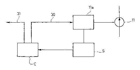
Figure 2 is a block diagram of the system according
to the invention.
In Figure 1, the number 1 globally designates and
LPG tank according to the prior art, to feed the LPG to
a plurality of injectors I associated to the various
cylinders of the engine. Z'he tank 1 has a hollow
structure 2 made in such a way as to assure its ability
to withstand the operating pressures expected for a
system of the type discussed herein. The hollow
structure 2 has an upper opening closed by a service
flange 3 bearing the various elements for joining and
connecting the tank to the feed system. For this
purpose, the tank 1 has a first through opening 4
through which is mounted the structure of an assembly 5
connected to a line 6 for the delivery of the LPG to a
distribution manifold or rail 7, which distributes the
LPG among the various injectors I. The assembly 5
includes a shut-off solenoid valve 8 destined to close,
shutting off the communication of t:he tank with the

CA 02453085 2003-12-16
exterior under predetermined emergency conditions, as
well as a flow rate limiter valve 9. The assembly 5
receives the LPG through the line 10 of the pump 11
driven by an electric motor lla whose structure is
5 connected by means of a connection element 12 to the
service flange 3. The pump 11 can in any case be
constructed in any other way, as will also be indicated
below. To the structure of the pump 11 is also
connected the structure of a device 13 for sensing the
LPG level. The electrical power supply of the solenoid
valve 8, of the pump 11 and of the sensor 13 is assured
by an electrical connector 14 which is mounted in a
through opening 15 of the service flange 3. Said flange
3 also has an additional through opening 16 into which
is mounted an assembly 17 comprising two valves 18 19.
The valve 18 is a return valve, which is connected to a
line 20 for the flow, into the tank, of the excess LPG
fed to the rail 7. The valve 19 is the valve used for
filling the tank and it is assbciated to an additional
level sensor 21. To the flange 3 is also associated a
safety valve 22 which prevents the pressure inside the
tank from exceeding a predetermined threshold value.
Figure 1 shows a traditional solution of a tank in
which the flange 3 has through hole: traversed by the
various components described above. The present
invention could also be embodied with a. tank having an
innovative structure which is the subject of the prior
Italian patent application no. T02001A000360 by the
same Applicant, in which at least some of the aforesaid
components are fastened to the lower surface of the
plate, without passing through it. Moreover, as stated
previously, in the case of the invention the operation
of the electric motor lla is not controlled by a level
sensor 13, but rather by the innovative means that will
be described hereafter. Lastly, the' mounting of the

CA 02453085 2003-12-16
6
motor-pump assembly, in the preferred embodiment of the
invention, is also different from the one indicated
purely by way of example in Figure 1, with reference to
the prior art.
With reference to Figure 2, a block diagram is
illustrated of the system according to the invention,
which comprises sensors S able to measure the
electrical current absorbed by the electric motor 11a
driving the pump 11. The sensor means S send their
output signal to electronic control means C which are
programmed in such a way that when the sensor means S
detect a reduction in the electrical current absorbed
by the electric motor lla below a predetermined
threshold value, the output a signal 30 which
interrupts the operation of the electric motor lla and
a signal 31 which activates the operation of an
auxiliary petrol feed system (not shown) with which the
engine is provided.
As indicated above, a much more precise and
reliable measurement is thereby obtained than in the
traditional system, in which the operation of the
electric motor lla is controlled by a sensor of the
level of liquid within the tank. ThE=_ signal output by
the sensor means S is able to assure that the electric
motor will be prevented from operating in conditions in
which there is a high risk of damage to said motor.
This result is obtained without risking unreliable
evaluations due to the variations irl the level of the
liquid in the tank, caused by the movements of the
vehicle, and continuing to assure the correct operation
of the motor when the level within the container that
surrounds it is sufficient, although. the level in the
remaining capacity of the tank is relatively low.
As was also previously stated,. said result is
obtained with extremely simple, low cost means.

CA 02453085 2003-12-16
7
Naturally, without altering the principle of the
invention, the construction details and the embodiments
may vary widely from what is described and illustrated
purely by way of example herein, without thereby
departing from the scope of the present inventions

Dessin représentatif
Une figure unique qui représente un dessin illustrant l'invention.
États administratifs

2024-08-01 : Dans le cadre de la transition vers les Brevets de nouvelle génération (BNG), la base de données sur les brevets canadiens (BDBC) contient désormais un Historique d'événement plus détaillé, qui reproduit le Journal des événements de notre nouvelle solution interne.

Veuillez noter que les événements débutant par « Inactive : » se réfèrent à des événements qui ne sont plus utilisés dans notre nouvelle solution interne.

Pour une meilleure compréhension de l'état de la demande ou brevet qui figure sur cette page, la rubrique Mise en garde , et les descriptions de Brevet , Historique d'événement , Taxes périodiques et Historique des paiements devraient être consultées.

Historique d'événement

Description Date
Demande non rétablie avant l'échéance 2008-12-16
Le délai pour l'annulation est expiré 2008-12-16
Réputée abandonnée - omission de répondre à un avis sur les taxes pour le maintien en état 2007-12-17
Inactive : Approuvée aux fins d'acceptation (AFA) 2007-10-31
Modification reçue - modification volontaire 2006-07-11
Lettre envoyée 2006-04-21
Toutes les exigences pour l'examen - jugée conforme 2006-04-04
Exigences pour une requête d'examen - jugée conforme 2006-04-04
Requête d'examen reçue 2006-04-04
Inactive : CIB de MCD 2006-03-12
Demande publiée (accessible au public) 2004-06-30
Inactive : Page couverture publiée 2004-06-29
Inactive : CIB attribuée 2004-03-26
Inactive : CIB en 1re position 2004-03-26
Lettre envoyée 2004-03-05
Inactive : Transfert individuel 2004-02-18
Inactive : Lettre de courtoisie - Preuve 2004-02-10
Demande reçue - nationale ordinaire 2004-02-02
Inactive : Certificat de dépôt - Sans RE (Anglais) 2004-02-02

Historique d'abandonnement

Date d'abandonnement Raison Date de rétablissement
2007-12-17

Taxes périodiques

Le dernier paiement a été reçu le 2006-11-21

Avis : Si le paiement en totalité n'a pas été reçu au plus tard à la date indiquée, une taxe supplémentaire peut être imposée, soit une des taxes suivantes :

  • taxe de rétablissement ;
  • taxe pour paiement en souffrance ; ou
  • taxe additionnelle pour le renversement d'une péremption réputée.

Les taxes sur les brevets sont ajustées au 1er janvier de chaque année. Les montants ci-dessus sont les montants actuels s'ils sont reçus au plus tard le 31 décembre de l'année en cours.
Veuillez vous référer à la page web des taxes sur les brevets de l'OPIC pour voir tous les montants actuels des taxes.

Historique des taxes

Type de taxes Anniversaire Échéance Date payée
Taxe pour le dépôt - générale 2003-12-16
Enregistrement d'un document 2004-02-18
TM (demande, 2e anniv.) - générale 02 2005-12-16 2005-11-17
Requête d'examen - générale 2006-04-04
TM (demande, 3e anniv.) - générale 03 2006-12-18 2006-11-21
Titulaires au dossier

Les titulaires actuels et antérieures au dossier sont affichés en ordre alphabétique.

Titulaires actuels au dossier
C.R.F. SOCIETA CONSORTILE PER AZIONI
Titulaires antérieures au dossier
CLAUDIO AMORESE
MARIO RICCO
ONOFRIO DE MICHELE
SISTO LUIGI DE MATTHAEIS
Les propriétaires antérieurs qui ne figurent pas dans la liste des « Propriétaires au dossier » apparaîtront dans d'autres documents au dossier.
Documents

Pour visionner les fichiers sélectionnés, entrer le code reCAPTCHA :


Pour visualiser une image, cliquer sur un lien dans la colonne description du document. Pour télécharger l'image (les images), cliquer l'une ou plusieurs cases à cocher dans la première colonne et ensuite cliquer sur le bouton "Télécharger sélection en format PDF (archive Zip)" ou le bouton "Télécharger sélection (en un fichier PDF fusionné)".

Liste des documents de brevet publiés et non publiés sur la BDBC .

Si vous avez des difficultés à accéder au contenu, veuillez communiquer avec le Centre de services à la clientèle au 1-866-997-1936, ou envoyer un courriel au Centre de service à la clientèle de l'OPIC.


Description du
Document 
Date
(aaaa-mm-jj) 
Nombre de pages   Taille de l'image (Ko) 
Abrégé 2003-12-15 1 22
Description 2003-12-15 7 331
Revendications 2003-12-15 2 92
Dessins 2003-12-15 2 41
Dessin représentatif 2004-04-14 1 5
Certificat de dépôt (anglais) 2004-02-01 1 160
Courtoisie - Certificat d'enregistrement (document(s) connexe(s)) 2004-03-04 1 105
Rappel de taxe de maintien due 2005-08-16 1 110
Accusé de réception de la requête d'examen 2006-04-20 1 190
Courtoisie - Lettre d'abandon (taxe de maintien en état) 2008-02-10 1 176
Correspondance 2004-02-01 1 27