Note : Les descriptions sont présentées dans la langue officielle dans laquelle elles ont été soumises.
CA 02454035 2004-O1-16
WO 03/007683 PCT/US02/22786
1
ORNAMENT AND JEWELRY CONSTRUCTION
The present invention relates to a new and improved construction of particular
utility in jewelry and other objects sought to be ornamented, as by
personalization and
the like. .
Background of the Invention
The wearer of a piece of jewelry, or other ornamented items, such as a belt,
often
desires that the item be somehow unique, or personalized to the wearer. This
is
conventionally accomplished by an artisan creating a unique design in
accordance with
the wearer's desires. It is accordingly a purpose of the present invention to
provide an
ornamentation construction which is both attractive and eye-catching, and
which has the
capability of being customized in accordance with the wants or desires of a
wearer.
It is further a purpose of the present invention to provide an ornamentation
for
incorporation into jewelry items, as well as other decorative items, and which
can be
utilized in a variety of styles, such as in bracelets, necklaces, and the
like.
Yet a further purpose of the present invention is to provide an ornament and
jewelry-type construction which can be changed and modified to provide
different
appearance aspects.
Brief Description of the Invention
In accordance with the foregoing and other objects and purposes, the ornament
and jewelry construction of the present invention comprises a peripheral frame
which
surrounds an interior panel. A plurality of spaced projections extend upwardly
from the
frame forming a design, which may be a letter, number or other pattern. The
panel may
be provided with a plurality of apertures, arranged in a matrix, into which
projection
elements bearing the projections may be placed. The projection elements
themselves
may have one or more individual projections extending upward from a common
base.
CA 02454035 2004-O1-16
WO 03/007683 PCT/US02/22786
2
The frame and panel may be formed as an integral unit, or the frame may be
insertable into the frame. An individual frame and panel construction may
serve as an
ornamental or jewelry item, such as a bracelet, pin or pendant. Alternatively,
frame and
panel units can be interconnected to form a bracelet, belt, or other extended
ornamental
construction, as well as signage or as an identification unit. The projection
elements
may be of varying or the same height and may have decorative material applied
to their
distal, projecting ends.
Brief Description of the Drawings
A fuller understanding of the present invention will be achieved upon
consideration of the following detailed description of preferred, but
nonetheless
illustrative embodiments thereof, when reviewed in conjunction with the
annexed
drawings wherein:
Fig. 1 is a plan view of a bracelet construction in accordance with the
invention;
Fig. 2 is an enlarged view of an individual frame and panel element of the
type
which may be incorporated into the bracelet of Fig. 1;
Fig. 3 is a section view taken along line 3-3 of Fig. 2;
Fig. 4 is a perspective view of a projection element used in connection with
the
invention;
Fig. 5 is a plan view of an alternative construction for a construction
utilizing a
plurality of frame and panel elements depicting how a plurality of the
elements
constructions may be joined thereto;
Fig. 6 is a further alternative construction depicting the interconnection of
frame
and panel elements;
CA 02454035 2004-O1-16
WO 03/007683 PCT/US02/22786
3
Fig. 7 is a detail plan view of a further alternate embodiment of the
invention in
which a plurality of panels are supported by a single peripheral frame unit in
a unitary
construction;
Fig. 8 is a partial sectional view taken along line 8-8 of Fig. 7;
Fig. 9 is an alternative representation of the type of construction of Fig. 7
wherein
the panels are constructed as independent elements mounted within the frame;
Fig. 10 is a section view taken along line 10-10 of Fig. 9; and
Fig. 11 is a perspective view of a projection element having a plurality of
projections extending from a common base.
Detailed Description of the Invention
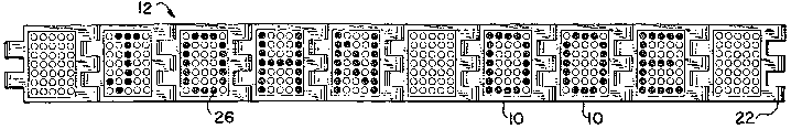
Referring initially to Figs. 1-3, the ornament/jewelry construction of the
present
invention comprises a constructional frame and panel unit 10 which
constructional units
may be used individually, such as for a pendant or as a ring fitting, or
alternatively, as
shown in Fig. 1, interconnected with other constructional units to form a
composite
ornament/jewelry construction, such as the belt or bracelet-like construction
of Fig. 1. It
is to be noted that in Fig. 1 the distal ends of the depicted construction 12
are shown
open. One skilled in the art will readily recognize that the ends can be
connected
together, or formed with an appropriate clasp mechanism, to form a closed
bracelet, belt
or necklace-type unit.
As depicted in Figs. 1-3, a constructional unit 10 comprises a peripheral
frame 14
which creates a border which encircles an inner panel 16. The frame and panel
may be
formed as an integral unit, such as by molding, from a variety of materials,
including
plastics, metal, rubber, leather and the like. Urethane is a presently
preferred material.
The panel may be recessed or inset from both the top surface 18 and lower
surface 20
of the frame, or may be located flush to the top or bottom. Alternatively, as
depicted in
CA 02454035 2004-O1-16
WO 03/007683 PCT/US02/22786
4
Figs. 9 and 10, the frame may be formed with an interior opening within which
the
panel, constructed as a separate element, is supported in a desired
orientation. The
frame 14 may include integral hinge knuckles 22 constructed as known in the
art to
allow the interconnection of constructional units 10 as depicted in Fig. 1. A
hinge pin
(not shown) may be inserted through the hinge knuckle of adjoining
constructional units
to permit the individual constructional units to pivot with respect to each
other, allowing
a closed loop or other sinuous shapes to be developed.
The panel 16 may be provided with a plurality of apertures 24 extending
between
its upper and lower surfaces. The apertures may be arranged in a regular,
matrix-like
pattern as shown in the figures, or may be located and arranged randomly or in
other,
specific designs or patterns. Each of the apertures 24 is dimensioned to
accept the
projection element 26. The projection elements 26 are inserted into selected
ones of
the apertures 24 in accordance with desired design criteria, and the shafts
extend
upwardly from the panel 16 to create a design. As depicted in Fig. 1, for
example, the
projection elements are mounted in the individual panels 16 of the overall
bracelet
construction 12 in a manner which creates the letters to spell out "JOHN DOE".
The top
surface of a projection element 26 may bear a colorant or reflective coating
28 to
enhance its visibility andlor attractiveness. Alternatively, the entire
projection element
may be colored or coated as desired to provide an appropriate visual effect.
It is to be
recognised that the design generated by the projection elements 26 may result
both
from different visual effects of the individual projection elements
themselves, as well as
a result of the projection elements being inserted into the selected apertures
20. Thus,
a wide variety of visual effects can be created by the choice of projection
elements and
their specific arrangement in the apertures of a constructional unit 10.
Indeed, desired
design effects may be created also by the lack of projection elements at
desired
locations, creating a shadow-like appearance.
Fig. 4 depicts an individual projection element 26. It may be formed
integrally
with the panel 16, along with other projection elements, in a desired pattern,
or
preferably be constructed to be insertable into an aperture as depicted in
Fig. 3. In the
CA 02454035 2004-O1-16
WO 03/007683 PCT/US02/22786
insertable form, it may be provided with a base 30 which, when the projection
element is
installed in an aperture of a panel element, abuts the bottom surface of the
panel and
prevents the projection element from being removed from the top of the
construction.
Alternatively, and as illustrated in Fig. 11, a plurality of individual
projection elements 26
may be formed with a single integral base portion 32. The base may be provided
with
notches 34 to allow the individual projection elements to be separated and
utilized
individually or in smaller combinations. While the projection element shown is
circular in
cross-section, other cross sections, such as ovals, squares, triangles, stars,
etc. may be
used. The aperture 24 may similarly be varied to accept the different shapes,
or may be
of a single, preferably circular shape dimensioned to functionally accept a
variety of
projection element cross-sections.
As depicted in Fig. 3, the projection elements 26 may be dimensioned so as to
have their top surfaces lying in the plane of the top surface 18 of the
peripheral frame
14. Alternatively, however, the projection elements may be of varying heights,
such that
they either extend above the height of the frame or lie below it, as depicted
in Fig. 8, at
varying heights, including flush with the top surface of the panel, to create
particular
visual effects, as desired.
The projection elements 26, when inserted into the panel 16, are preferably
dimensioned to be frictionally retained therein. Particularly when the panel
is created of
a resilient material, such as urethane, the projection elements can be
constructed of a
wide variety of materials, including metal and plastic, and can be held in
place by the
resiliency of the panel. To further ensure that the projection elements are
not
inadvertently or accidentally dislodged, however, a rear closure may be
employed. As
seen in Fig. 3, for example, the rear closure may comprise a door-like panel
36 which is
pivotally mounted at 40 to the peripheral frame 14 and is positioned to close
off the
recessed area behind and below the inserted projection elements 26. The inner
sidewall 34 of the panel 16 opposite the pivot 40 may be beveled to
accommodate a
corresponding-shaped edge 42 of the door to provide a locking function.
CA 02454035 2004-O1-16
WO 03/007683 PCT/US02/22786
6
As depicted in Figures 5, 6 and 7, a peripheral frame 14 may take any of a
variety of shapes. In addition to the generally rectangular construction with
two
opposed hinge knuckles 22 as depicted in Fig. 2, other frame constructions can
be
utilized, such as the hexagonal design as depicted in Fig. 5. The means for
interconnecting adjacent constructional units, such as the hinge knuckles 18,
may be
applied to any number of the edges, such as all edges, as shown. Inclusion of
such
interconnection means along the entire periphery of a constructional unit 10
can allow
large overall constructions to be realized. Fig. 6 depicts a rectangular frame
14 having
the hinge knuckles on all four sides.
Figs. 7 and 8 depict a construction in which a constructional unit 44
comprises an
elongated peripheral frame 46 and a correspondingly elongated panel 48 formed
integrally with the frame. The panel 46 is again positioned within the frame
46,
recessed from the frame's top and bottom surfaces. Rather than bearing a
continuous
matrix of apertures 24 thereon, however, the panel 48 is divided into a
plurality of
separated aperture bearing sections 50 which mimic the layout of the
construction of
Figure 1 in which individual constructional units 10 are assembled in a linear
or side-by-
side manner. To create the appearance of separate constructional units, the
frame 48
is provided with a series of intermediate border portions 52, which serve to
divide the
panel into a series of portions 50. The border portions extend downwardly, as
seen in
Fig. 8, their bottom surfaces being flush with the bottom peripheral surface
of the frame.
Thus, while the constructional unit 44 is of an integral construction, it
provides a
construction which replicates the existence of individual panel elements. The
projection
elements 26 are again inserted into the apertures in a desired pattern. The
present
construction also depicts a structure which does not utilize door panels, the
projection
elements 26 being retained in the apertures solely by frictional engagement
therebetween.
Figs. 9 and 10 depict yet a further alternative construction, similar to that
of Figs.
7 and 8, in which an elongated peripheral frame 54 is provided. In this
construction,
however, there are a plurality of individual, independent panels 56 which are
each
CA 02454035 2004-O1-16
WO 03/007683 PCT/US02/22786
7
frictionally retained by a portion of surrounding peripheral wall 58 of the
peripheral frame
54 and interior border 62. As shown, the peripheral wall and border of the
frame is
provided with an internal shoulder 60 against which the panel 56 rests when
inserted
from the rear of the construction. The dimensions of the panel 56 are chosen
to provide
a snug fit whereby it can be retained within the frame. In this construction,
a door panel
36 can be utilized to further assist in retaining the panel, with the
projection elements 26
mounted therein, within the frame. Other mounting for the panels ~ can be used
to
position the panel as desired within the frame.
It is to be appreciated by those skilled in the art that the foregoing
embodiments
are intended to be merely illustrative of the present invention and that other
variations
and modifications thereto can be accomplished without departing from the true
scope of
the invention.