Note : Les descriptions sont présentées dans la langue officielle dans laquelle elles ont été soumises.
CA 02454141 2003-12-23
Description
CAP
Field of Invention
This invention relates generally to a cap for a pedestal adapted to support
adjacent floor panels defining a raised floor; and particularly relates to a
cap for
capturing a pedestal and for presenting a plurality of ribs for locating the
floor panels.
Backg~~round Art
Elevated floors or access floor panels have gained wide spread acceptance in
the marketplace with the advent of the computer age. In particular, elevated
floors are
comprised of a plurality of access floor panels which are arranged in side by
side
relation in an array generally supported at their corners by a plurality of
pedestals.
Furthermore, stringers which are generally horizontal support members that
span
between the pedestals, may also be utilized to support the edges of a floor
panel in a
manner well known to those person skilled in the art.
Since there are many stringers and pedestals that are utilized to support a
plurality of access floor panels to define the raised floor, there is a need
to accurately
and quickly locate adjacent floor panels in an efficient manner.
Furthermore, some prior art access floor panel systems include the placing of
floor panels which can be comprised of metal onto the pedestals which are also
duly
comprised of metal. When a person walks upon the metallic floor panels and
pedestals
they can slide relative to one another so as to produce a noise such as a
squeak or the
like. It is generally preferable to attempt to eliminate or minimize this
noise.
CA 02454141 2003-12-23
-3-
U.S. Patent No. 4,558,544 illustrates a cushioning pad comprising a pad base
and hoods which are open at the periphery of the pad base. When the cushioning
pad
is installed on a head member, each of the hoods receives one of the lugs and
the lower
face of the pad maybe provided with a layer of adhesive.
Furthermore, the U.S. Patent No. 4,996,818 teaches a polymeric base plate
covered with carpet and featuring resilient tabs which are inwardly recessed
from the
side edges of the plate. Other arrangements are shown in U.S. Patent No.
4,656,795
which relates to a head member presenting sets of mutually perpendicular
regularly
extending upstanding lugs arranged where adjacent lugs receive and retain a
corner of
the floor panels.
Moreover, U.S. Patent No. 4,570,397 relates to a device where each of the
pedestals is adjustably positioned both in a vertical and angular manner to
position the
top most portion of each unit in an even parallel plane. Furthermore, U.S.
Patent No.
3,938,295 teaches an access floor system with deep pile carpet covered panels.
The
deep pile fibers from adjacent panels intermingle with each other to visually
obscure the
cracks between the panels.
Finally, U.S. Patent No. 3,943,674 teaches a false floor assembly of square
panels supported on pedestals above a foundation. The panel corners rest on
pedestals and the adjacent sides of neighbouring panels between pedestals are
secured together by releasable ties that pass through the sides of each
neighbouring
panel. The area below the panels is accessible by simply removing the ties and
lifting
one or more panels from the assembly.
Other arrangements are shown in US patent 3,318,057 which illustrates a cap
resting on a curved top portion of a pedestal .
These and other prior art structures and devices present relatively
complicated
structures.
CA 02454141 2003-12-23
-4-
It is an object of this invention to provide an improved device and method for
locating and stabilizing adjacent access floor panels. It is another object of
the invention
to provide a cap capable of laterally securing floor panels.
It is an aspect of this invention to provide a cap for a pedestal adapted to
support
adjacent floor panels defining a raised floor said cap comprising a bottom
surFace for
contacting said pedestal, said bottom surface including structure for
capturing the
pedestal; a top surface presenting a plurality of ribs for locating said floor
panels.
It is a further aspect of this invention to provide a raised access floor
system
comprising of a plurality of floor panels arranged in side by side relation,
said panel
supported at their edges by stringers and at their corners by pedestals, said
pedestal
having an upper pedestal plate, and a cap adapted to snap onto said pedestal
plate,
wherein said cap presents a substantially rectangular top and bottom surface
defining
four corners, said bottom surface supported by said upper pedestal plate; said
top
surface including a plurality of ribs for locating corners of adjacent floor
panels and
locating ends of said stringer.
It is yet another aspect of this invention to provide a method of locating
corners of
a floor panel for support by a pedestal comprising the steps of placing a cap
over said
pedestal, said cap having capturing means for capturing said pedestal; a
plurality of
upstanding ribs for locating and stabilizing stringers between spaced apart
ribs and for
locating and stabilizing said corners of said floor panels between adjacent
ribs.
These and other objects and features of the invention shall now be described
in
relation to the following drawings:
Brief Description of Drawing
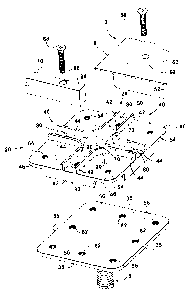
Fig. 1 is a partial exploded view of the invention.
CA 02454141 2003-12-23
-5-
Fig. 2 is a top plan view of the cap.
Fig. 3 is a partial side elevational view of a pedestal and the cap.
Best Mode for Carrying Out the Invention
In the description which follows, like parts are marked throughout the
specification and the drawings with the same respective reference numerals.
The
drawings are not necessarily to scale and in some instances proportions may
have
been exaggerated in order to more clearly depict certain features of the
invention.
Generally speaking a plurality of floor panels 2 are adapted to be supported
at
their corners 4 by a plurality of pedestals 6 in a manner well known to those
persons
skilled in the art. Furthermore the edges 8 may be supported by stringers 10
again in a
manner well known to those persons skilled in the art.
The pedestals 6 include a threaded rod 12 to adjust the height of the pedestal
plate or head 14 relative to the floor (not shown} by turning or rotating the
threaded rod
12 vertically up or down as shown in Fig. 3. When the desired height is
attained the
adjusting nut 16 is manipulated so as to lock the height in place.
A cap 20 is provided which has a bottom surface 22 and top surface 24. The top
and bottom surface 22 and top surface 24 present a generally rectangular shape
and in
one embodiment include a square shape as shown in Figs. 1, 2 and 3, which are
substantially flat.
The bottom surface 22 includes capturing means 26 to capture the upper
pedestal 14. In particular, the capturing means 26 includes a plurality of
snap on tabs
28 which are generally disposed along each of the edges 30, 32, 34 and 36. In
one
embodiment the cap 20 is comprised of plastic and the tabs 28 include a
bevelled edge
CA 02454141 2003-12-23
-6-
32 which is adapted to contact the pedestal plate 14 and spring outwardly so
as to
capture the edges as shown. More specifically the capturing means include a
recess 33
adapted to receive the edges 35 of the pedestal 14.The tabs 28 project
inwardly relative
to the edges 30, 32, 34 and 36 of the cap 20 as shown by tines 38.
The figures show that the tabs 28 do not extend along the entire edges 30, 32,
34, and so as to permit sliding movement of the cap 20 relative to the
pedestal plate 14.
However, it is possible the tabs 28 can extend all the way around the
periphery and be
sized so as to permit some sliding motion. In another embodiment the cap can
be sized
to permit little sliding motion of the cap 20 and pedestal plate 14.
The upper surface 24 of the cap 20 includes a plurality of ribs 40 for
locating the
floor panels 2. In particular the upper surface 24 of cap 20 includes a
plurality of
adjacent ribs 42 and 44 located in each of the corners 46 of the upper surface
24 of the
cap 20. The adjacent ribs 42 and 44 and each of the corners 46 are adapted to
locate
and laterally stabilize the bottom 50 of a floor panel 2 as well as the sides
52 of the floor
panel without fasteners. Alternatively fasteners may be used as described
below.
Each of the corners 46 define quadrants on the top surface 24 of the cap 20.
Each of the corners or quadrants include holes 54 which are adapted to align
co-axially
with threaded holes 56 presented by the upper pedestal plate 14. Accordingly
one of
the corners 4 of the floor panel 2 is located by the upstanding adjacent ribs
42 and 44. A
panel fastener 58 may be placed within a hole 60 which is disposed through the
upper
surface 62 of the floor panel 2 and the bottom 50 of the floor panel 2 to be
aligned With
the hole 54 for fastening to the threaded hole 56. Each of the corners 4 of
adjacent
panels 2 may be attached in the same way so that edges 8 of adjacent panels 2
are
disposed opposite each other so as to define a floor system.
The ribs 40 are also disposed in a manner so as to present a first set of
spaced
apart ribs 42 disposed along a first direction 70 and a second set of spaced
apart ribs
44 disposed along a second direction 72. First direction 70 is disposed
substantially
CA 02454141 2003-12-23
_ 7
perpendicular to the second direction 72 so as to define a first central
region disposed
along direction 70 and a second central region disposed along direction 72.
The
spaced apart ribs 42 and 44 are adapted to locate and stabilize stringers 10
which may
also be placed on top of the caps 20 as shown in the drawings. In other words
in
another embodiment of the invention stringers 10 may be used.
The cap 20 includes a plurality of holes disposed between spaced apart ribs 42
and 44 Which holes 80 are adapted to be aligned with threaded holes 82
disposed in the
pedestal plate 14.
Each of the ends 84 of the stringers 10 include a hole 86 adapted to receive a
stringer fastener 88 Which aligns with the holes 80 and the threaded holes 82
so as to
fasten the stringer to the pedestal plate 14.
The spaced apart ribs 42 and 44 are arranged in substantially parallel spaced
apart relation as shown in centered about central regions defined by first
direction 70
and second direction 72.
The adjacent ribs 42, 42 and 44, 44 are disposed generally perpendicular to
one
another and may merge with one another to define the curve portion 90.
The snap on cap 20 as shown may be snapped on to an existing flat pedestal
plate 14. The snap on cap 20 locates the access floor panel 2 and provides
lateral
stability. This provides an inexpensive cost-effective method of providing
positive
location and lateral stability of the access floor panels 2 mounted to the top
of an
adjustable pedestal support.
The cap 20 can be comprised of a variety of materials including plastic or the
like
thus eliminating metal to metal contact between the panel 2 and the pedestal 6
thereby
reducing squeak and rattle in the access floor system.
CA 02454141 2003-12-23
_ g
Moreover the method of locating corners of the floor panel for support by the
pedestal comprises the steps of placing a cap over the pedestal where the cap
has
capturing means for capturing the pedestal 6, and a plurality of upstanding
ribs 42 and
44 for locating and stabilizing stringers and corners of the access floor
panel 2. The
snap on method of application is generally fast and allows for cost effective
installation.
In one embodiment of the invention the cap locates the floor panels 2 and
provides lateral stability.
The method described herein provides an inexpensive fast method of providing a
positive location and lateral stability of an access floor panel 2 mounted to
the top of the
adjustable pedestal support and eliminating metal to metal contact between the
panel
and pedestal which reduces squeak and rattle in the access floor system. The
snap on
cap supplies location of the panel and stringer if required.
Various embodiments of the invention have now been described in detail. Since
changes in and/or additions to the above-described best mode may be made
without
departing from the nature, spirit or scope of the invention, the invention is
not to be
limited to said details.