Note : Les descriptions sont présentées dans la langue officielle dans laquelle elles ont été soumises.
CA 02454668 2004-O1-22
WO 03/013834 PCT/US02/24793
1
THERMALLY INSULATIVE SLEEVE
Related Application
This application is based on and claims the benefit of U.S.
Provisional Application No. 60/310,392, filed August 6, 2001.
Field of the Invention
This invention concerns sleeving for encasing and
protecting elongated substrates such as wiring harnesses, fuel
lines, brake lines and the like subjected to harsh thermal
environments.
Background of the Invention
Elongated substrates, such as wiring harnesses, fluid
conduits, such as brake lines and fuel lines, and optical fiber
bundles, are often used in automotive, aerospace and marine
applications where they are subjected to intense heat. Wiring
harnesses and fuel lines routed through an enclosed engine
compartment, for example, in an automobile, boat or aircraft, are
subjected to both radiant and connective heat from the engine,
particularly the exhaust manifold. Similarly, fuel lines and
wiring in the vicinity of a rocket engine nozzle or on an
orbiting satellite, exposed to direct sunlight in the vacuum of
space, require thermal protection to ensure proper and continued
operation.
Thermal protection has been afforded by the use of
composite protective sleeving comprising a layer of woven glass
fiber bonded to a layer of reflective metal foil. Flat sheets of
the composite are reverse folded with the reflective metal foil
layer facing outwardly. Opposite edges of the sheets are
CA 02454668 2004-O1-22
WO 03/013834 PCT/US02/24793
2
positioned adjacent to one another and sewn together forming a
longitudinal seam.
While such sleeving provides thermal protection, it is
relatively expensive and time consuming to manufacture, largely
due to the sewn longitudinal seam. Furthermore, such a seam
inevitably leaves layers beneath the reflective layer, such as
the glass fiber layer, exposed to the thermal environment. The
exposed layers compromise the thermal shielding otherwise
afforded by sewn sleeves and allow a relatively hot region to
form along the substrate within the sleeve. Additionally, the
reverse fold results in a lengthwise crease along the sleeve
which significantly weakens the glass fiber layer, decreasing its
tear strength by as much as 75% and, thus, providing a failure
initiation point on the sleeve. There is clearly a need for a
thermal protective sleeve which avoids the disadvantages of the
sewn sleeve and which can be produced more rapidly without the
need for sewing.
Summary and Objects of the Invention
The invention concerns an insulative, flexible sleeve for
protecting elongated substrates subjected to harsh thermal
environments. The sleeve is formed from a composite sheet
comprising a metallic reflective layer, a reinforcing layer and
an insulative layer.
The metallic reflective layer is preferably aluminum,
either in the form of a thin foil adhered to the reinforcing
layer or as a vacuum deposited coating. Preferably the
reinforcing layer comprises a flexible, tear-resistant material
such as Mylar that substantially overlies the reflective layer.
The insulative layer comprises a fibrous, non-woven material,
preferably a thermoplastic felt having a predetermined thickness
providing air spaces for increased insulative capability. The
insulative layer substantially overlies and is attached to the
reinforcing layer, preferably using adhesive.
Upon forming the layers into a composite sheet, a reverse
fold is formed between a first and a second portion of the sheet
CA 02454668 2004-O1-22
WO 03/013834 PCT/US02/24793
3
so as to bring the first sheet portion into overlying relation
with the second sheet portion. The fold places the insulative
layer on the first sheet portion in facing relation with the
insulative layer on the second sheet portion, the reflective
layer faces outwardly. A seam is formed between the first and
second sheet portions attaching them together. Preferably, the
seam is formed by fusing the facing insulative layers on the
first and second sheet portions together using ultrasonic welding
techniques. The seam is positioned along the sheet in spaced
relation to the reverse fold. Together, the
first and second sheet portions, the reverse fold and the seam
define a central space therebetween adapted to receive elongated
substrates to be insulated.
It is an object of the invention to provide a thermally
insulative sleeve for elongated substrates.
It is another object of the invention to provide a sleeve
insulating against all modes of heat transfer.
It is again another object of the invention to provide a
sleeve having a non-woven insulative layer.
It is yet another object of the invention to provide a
sleeve formable by welding the insulative layer to itself to form
a seam.
It is still another object of the invention to provide a
sleeve wherein the welding is performed by ultrasonic welding
techniques.
These and other objects and advantages of the invention
will become apparent upon consideration of the following drawings
and detailed description of preferred embodiments.
Brief Description of the Drawings
Figure 1 is a cross-sectional view of a composite sheet
prior to folding and welding to form a thermally insulative
sleeve according to the invention;
CA 02454668 2004-O1-22
WO 03/013834 PCT/US02/24793
4
Figure 2 is a perspective view of a sleeve according to the
invention; and
Figure 3 is a cross-sectional view taken along lines 3-3 of
Figure 2.
Detailed Description of the
Preferred Embodiments
Figure 1 shows a sectional view of a composite sheet 10
used to form a thermally insulative sleeve according to the
invention. Sheet 10 preferably comprises three layers, an
insulative layer 12 of a fibrous, non-woven material, a
reinforcing layer 14 of a flexible, tear-resistant material and a
reflective layer 16. The layers are preferably adhesively bonded
together using thermoplastic polyester adhesive or cross-linked
polyester adhesive for increased interlaminar shear strength and
resistance to adhesive failure at relatively high temperatures.
The layers are arranged with the reinforcing layer 14 sandwiched
between the reflective layer 16 and the insulative layer 12.
This permits the reinforcing layer 14 to reinforce both adjoining
layers 12 and 16 without interfering with the thermal protective
and insulative functions of either layer as described below.
The reflective layer 16 is preferably comprised of a metal
foil, for example, aluminum, or gold for increased reflectivity.
Practical aluminum foil thicknesses used with the sleeve range
between 0.00035 to about 0.001 inches with a thickness of about
0.00035 inches being preferred for most common automotive
applications. Relatively thin foils are preferred to preserve
the flexibility of the sleeve and allow it to readily conform to
the shape and path of the substrate which it is covering.
Reflective layer 16 may also be formed by a metallic coating,
such as aluminum, vacuum deposited directly onto the reinforcing
layer 14.
The reinforcing layer 14 is preferably Mylar which provides
excellent tear-resistance (even when folded or creased) and which
readily bonds to the other layers comprising the composite sheet
10. Mylar also provides an excellent substrate for vapor
CA 02454668 2004-O1-22
WO 03/013834 PCT/US02/24793
deposition of metallic coatings. The reinforcing layer 14 is
primarily present to prevent the reflective layer 16 from
tearing, the relatively thin metallic layer being delicate and
easily torn. Other tough materials, such as kapton, may also be
5 used in place of Mylar, but Mylar is generally preferred,
particularly for automotive applications due to its availability
and relatively low cost.
The insulative layer 12 is preferably comprised of a
fibrous, non-woven thermoplastic felt, such as polyester felt,
l0 which obtains its thermal insulating characteristics largely from
the presence of the significant quantity of air which is trapped
between the fibers forming the felted material. Other feasible
felt materials include polypropylene, acrylic, nylon, as well as
other thermoplastics. The areal density of the felt for
practical applications ranges between about 1.5 ounces per square
yard to about 7.25 ounces per square yard. The preferred felt
density for most automotive applications is about 4.5 ounces per
square yard. The areal density of the felt determines the amount
of air trapped within the felt, with greater density felt
trapping more air~and, thus, having relatively increased
insulative capacity. Denser felts, however, are thicker and less
flexible and may not conform to the shape and path of their
substrate as well as thinner felts. Thus, the mid range of felt
density represents a feasible compromise between the insulative
characteristics and the flexibility of the sleeve.
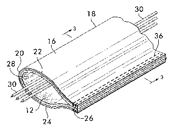
Figure 2 shows a sleeve 18 formed from the sheet 10 of
Figure 1. Sleeve 18 is formed by reverse folding sheet 10 along
a reverse fold 20 with the reflective layer 16 facing outwardly,
thereby dividing the sheet 10 into first and second sheet
portions 22 and 24. The reverse fold 20 brings the sheet
portions 22 and 24 into overlying relation with the insulative
layer 12 on the first sheet portion 22 facing the insulative
layer 12 on the second sheet portion 24. First and second sheet
portions 22 and 24 are attached to one another along a seam 26
positioned in spaced relation to the reverse fold 20 and
extending lengthwise along the sleeve 18. Together, the first
and second sheet portions 22 and 24, the reverse fold 20 and the
CA 02454668 2004-O1-22
WO 03/013834 PCT/US02/24793
6
seam 26 define a central space 28 for receiving an elongated
substrate, such as wiring harness 30.
As best shown in Figure 3, seam 26 is preferably formed by
positioning opposite edges 32 .and 34 of sheet 10 adjacent to each
other and joining them together, preferably by ultrasonic welds
36 (see Figure 2), which fuse the facing insulative layers 12 on
each sheet portion 22 and 24 together. The welds 36 are
effectively applied through the reflective and reinforcing layers
and are actually formed between the felt layer 12 in a region
adjacent to each edge 32 and 34. The strength of the ultrasonic
weld is proportional to the density of the felt. Denser felt
means more material being welded together and, hence, a
relatively stronger seam than would be formed by welding lower
density felt. Thermoplastic felt is preferred because it welds
readily to itself to form a strong bond.
The welds are formed by feeding the edges 32 and 34 of the
folded composite sheet 10 between a vibrating horn and a rotating
welding head comprising the ultrasonic welder. The welding head
rotates in the feed direction of the sheet. A plurality of
raised portions are arranged circumferentially around the head
which force the sheet edges into contact with the vibrating horn
at discrete points along the sheet as the raised portions pass
the horn. The vibration of the horn imparts energy to the
insulative felt layer 12 which heats it and causes the polyester
fibers comprising the layer to fuse together. Depending upon the
required strength of the seam, single or multiple rows of welds
may be laid down by the welder.
Ultrasonically welding the edges 32 and 34 to form the seam
26 provides several advantages over other methods of joining the
edges, such as sewing or using fasteners. Sewing requires that
the layers be pierced, thus, weakening them and compromising the
integrity of the reflective layer, reducing its reflective
characteristics. The welds form a substantially continuous,
sealed seam with no openings exposing non-reflective underlayers
through which radiation or convective heat may penetrate. The
ultrasonic welder has a high rate of material throughput,
CA 02454668 2004-O1-22
WO 03/013834 PCT/US02/24793
7
allowing for high rates of production. There is, furthermore, no
need for extra materials or components, such as thread or
fasteners, since the weld is formed between elements which are
already an integral part of the sheet.
The sleeve 18 thus formed provides thermal protection for a
substrate 30 within the central space 28 by effectively blocking
all modes of heat transfer. The reflective outer layer 16 blocks
radiant thermal energy, which is significant at relatively high
temperatures. The insulative felt layer 12, by providing an
insulating layer of air trapped within the felt, blocks both
convective and conductive heat transfer to the substrate. By
positioning the reinforcing Mylar layer 14 between the reflective
and insulative layers, both layers are reinforced without
adversely affecting the thermal performance of either layer,
since ambient radiant heat sees only the outer reflective surface
and the air gap provided by the felt is adjacent to the substrate
30.
Flammability testing of the sleeve according to the
SAE J369 standard indicates that it is self-extinguishing.
Emissivity testing of the sleeve according to ASTM E-408,
Method B, is expected to show an emissivity of about 0.14.
Emissivity may be considered the complement of reflectance for
practical purposes, and an emissivity of 0.14 indicates that
approximately 86% of incident radiation should be reflected from
the sleeve. The sleeve should withstand temperatures between
-40°F and 450°F and deliver significant thermal protection when
subjected to an 800°F infrared source such that the surface
temperature of the sleeve should remain at about 230°F, and the
temperature of the space within the sleeve should remain at about
215°F.
The ultrasonically welded, non-woven insulative sleeving
according to the invention provides a cost-effective means for
thermally protecting elongated substrates in a wide variety of
applications while avoiding the disadvantages of higher cost,
lower production rates, decreased tear strength and incomplete
thermal protection associated with previous insulative sleeving.