Note : Les descriptions sont présentées dans la langue officielle dans laquelle elles ont été soumises.
CA 02455363 2004-O1-16
-1-
LEAK DETECTION SYSTEM AND
METHOD FOR OFFSHORE HOSE LINES
Field of the Invention
(001) The invention relates generally to offshore pumping stations and, more
specifically, to hose leak detection systems deployed within the context of
such pumping
stations.
Background of the Invention
[002) In offshore pumping operations, there is a systematic risk of oil
leakage to the sea
from damage to single carcass submarine or floating oil suction and discharge
hoses. As
used herein, a "single carcass hose" is a hose construction comprising only
one carcass
layer. Leakage from a single carcass hose may from a precipitous hose failure
or a
failure that materializes over time. Hose failure may result from overpressure
of the
system, a puncture from outside, sudden tensile break of the hose body,
defects in the
manufacture, construction or design of the hose, etc. In a single carcass hose
construction, hose failure results in immediate oil leakage to the environment
surrounding the hose. Such leakage is highly undesirable for obvious
environmental and
economic reasons.
[003] Because of the risk of failure inherent in single carcass hose
construction, a
"double carcass" hose construction has been proposed and developed by those in
the
industry. A double carcass hose construction utilizes an outer hose carcass
confining an
inner hose carcass as an added safeguard. The outer hose functions to hold any
oil or
fluid that leaks through the inner hose carcass for a certain designed period
of time. In a
typical double carcass construction, a hose includes a main pressure cord or
carcass layer
as a primary confinement and an outer, or auxiliary, pressure cord layer
formed so as to
sheathe the inner carcass. A buffering space is defined between the carcass
layers to
retain fluid that leaks from the inner carcass. In use, it is common to
connect hoses end-
to-end to form a hose line for transporting oil or other fluid under pressure.
U.S. Patent
No. 5,244, 016 discloses a hose representative of the state of the art double
carcass
construction.
CA 02455363 2004-O1-16
-2-
[004] A double carcass hose is generally produced and utilized in two
different types:
submarine or floating configurations, depending on the type of application and
offshore
oil pumping system. Submarine applications require that a hose extend in
submerged
fashion between two points whereas a floating application requires that the
hose extend
across the water surface. In either application, leakage from the hose results
in the
aforementioned undesirable consequences.
[005] In order to minimize the damage resulting from an undetected leak,
various leak
detection systems have been proposed and adopted. Such systems generally are
based in
theory on observation or mechanical manipulation of a hose to ascertain the
existence
and location of a leak. Mechanical manipulation may take the form of twisting
a hose
along its axis; scoring of the outer hose carcass; or a pin located at the
hose nipple that
indicates by its position whether a leak is present. Mechanical systems,
however, require
visual inspection by professional scuba divers. Such visual inspections can
only be
conducted, as a practical matter, during daylight because visibility is
extremely limited
during night hours. Limiting pumping operation to daylight hours, as is
commonly done
in pumping operations, results in production inefficiency. Inclement weather
conditions,
moreover, may periodically make the utilization of divers to inspect hose
lines
impossibly dangerous. The delays associated with waiting for weather to clear
further
adds operational cost. In addition, the labor cost associated with deployment
of
professional divers to inspect hose lines is considerable. Accordingly,
mechanical
systems requiring visual inspection, while better than no leak detection
system, represent
a less than ideal solution to the industry's need for a reliable and cost
effective hose leak
detection system.
Summary of the Invention
[006] The present invention obviates the deficiencies with state of the art
hose leak
detection by providing a system that remotely senses the existence and
location of a leak
without the need for a visual inspection. An oil leak detection device and
system is
installed in the hose in communication with a collection space between inner
and outer
carcass layers of the hose. The oil leak detection device communicates
information
CA 02455363 2004-O1-16
-3-
relating to the presence or absence of fluid within the collection space to a
remote
location.
[007) According to a further embodiment of the invention, the leak detection
device is
positioned within a chamber that is incorporated within the hose nipple. The
chamber
communicates with the collection space and collects oil leaking through the
inner carcass
into the collection space between the inner and outer carcass layers.
[008] According to a further embodiment of the invention, the oil leak
detection device
is an electronic sensor having detection means for detecting the presence and
absence of
fluid in the collection chamber, and communication means for transmitting
information
regarding the fluid status within the collection chamber to a remote display
unit. The
display may include visual indicia identifying the status and location of a
plurality of
sensor devices in a hose line system.
[009) According to another embodiment of the invention the detection means may
utilize optical means for detecting the presence and absence of fluid in the
collection
chamber.
[0010] According to a further embodiment of the invention, detection means may
be
located at each of two opposite ends of a hose line segment in a hose system
comprising
hose line segments coupled end-to-end.
[0011] Yet a further aspect of the invention is to provide a method for leak
detection in a
double carcass hose line system comprising the steps: positioning at least one
detection
means in communication with a fluid collection space between the inner and
outer
carcass of a hose line segment, the detection means including means for
detecting the
presence and absence of fluid in the collection space; communicating
information
regarding the fluid status of the collection space to a remote location; and
indicating at
the remote location the fluid status within the collection space.
[0012] These and other embodiments and aspects of the invention, which will be
apparent to those skilled in the art, are achieved by a preferred embodiment
that is
described in detail below and illustrated in the accompanying drawings.
Brief Description of the Drawings
[0013] The invention will be described by way of example and with reference to
the
accompanying drawings in which:
CA 02455363 2004-O1-16
-4-
FIG. 1 is a schematic representation of one application of the subject
invention in
an offshore oil pumping station.
FIG. 2 is a right front perspective view of a fluid detection sensor pursuant
to the
invention.
FIG. 3 is a side elevation view of the fluid detection sensor with portions in
section for the purpose of illustration.
FIG. 4 is a plan view of a representative display unit configured pursuant to
the
invention.
FIG. 5 is a side elevation view partially in section of a hose nipple having a
fluid
detection sensor incorporated therein pursuant to the invention.
Detailed Description of the Preferred Embodiments
[0014] Referring initially to FIG. l, an offshore oil drilling application is
depicted by
way of example incorporating a double carcass hose with built-in electronic
remote oil
leak detection system 10 configured pursuant to the subject invention. The
offshore oil
drilling station of FIG. 1 is but one of many applications for the invention
and the
invention is not intended to be limited thereto. Any application in which a
double
carcass hose is utilized for the transportation of a fluid can utilize the
subject leak
detection system and the teachings herein set forth.
[0015] The representative field application of FIG. 1 is schematically
represented by a
tanker or platform 12 on which a control unit or panel 14 (FIG. 4) is located.
Extending
from the tanker 12 is a network of floating hose lines 16 comprising end to
end
connected hose segments 18 joined together by a coupling 20. The floating
lines 16
extend to a buoy 22 and connect thereto by a coupling 24. Submarine hose lines
26
depend from buoy 22 and comprise hose segments 28 connected end to end by
couplings
30. Submarine hose lines 26 terminate at a pump station 32. Oil is pumped from
station
32 upward through hose lines 26 to the floating lines 16 and therein to the
tanker 12.
Pursuant to the invention, as explained in detail below, leak detection
sensors 34 are
disposed within the hose lines 16 and 26 to detect fluid leakage and prevent
the fluid
from escaping into the sea. Preferably, although not necessarily, each hose
segment is
provided with two sensors 34. More or fewer sensors per hose line or hose line
segment
may be deployed if desired.
CA 02455363 2004-O1-16
-5-
(0016] A representative electro-optic embodiment of a fluid detection sensor
34 is shown
in FIGS. 2 and 3. While the embodiment illustrated is a preferred form for the
sensor 34,
the subject invention is not intended to be so limited. Other forms of sensors
and
associated circuitry for detecting the presence of fluid and generating a
warning signal in
the event of leak detection, that will be apparent to those skilled in the
art, may be
deployed if desired. By way of example, without representing an exhaustive
list, liquid
detectors based upon chemical, thermal, mechanical, or other physical
properties and
principles may be substituted to detect leakage fluid. The form of detector 34
shown
FIGS. 2 and 3 represents one embodiment for performing the desired fluid
detection
function.
[0017] With continued reference to FIGS. 2 and 3, the detector 34 is a
substantially
cylindrical body 36 formed of a hard material such as steel. The body 36
extends
forward to a sensor tip 37, comprising a spaced apart coupled electro-optic
transmitter
and receiver devices 38, 40. The devices 38, 40 are custom made to fit this
specific
application, but use common use commercially available technology. The
transmitter 38
and receiver 40 are separated by a gap 41. At the rearward end of the body 36
is a
threaded bolt coupling 42. Electrical leads 44 are routed into the body 36
from the
rearward end. A protective covering 46 surrounds the forward tip 37 of the
body 36 and
is formed of a suitable material such as thermoset or thermoplastic resin. A
custom
made microprocessor 48 is enclosed within body 36, of a type using
commercially
available technology. Output terminals of processor 48 are connected in series
to the
transmitter 38 and receiver 40 by leads 52, 54, respectively. A battery 50 is
further
provided to power the microprocessor 48 and electro-optic devices 38, 40.
(0018] Sensor 34, it will be appreciated, functions to detect the presence of
fluid at the
tip end 37. The electronic circuitry of sensor 34 is essentially an open
circuit switch. In
the absence of fluid, an optical beam is generated by transmitter 38,
traverses gap 41, and
is received by receiver 40. When the beam is interrupted by, in the subject
application,
the presence of oil between devices 38, 40, a short circuit is caused and the
electronic
circuit (switch) closes. Upon closing, an electronic signal is sent via leads
44 to the
remote control unit depicted in FIG. 4, located in a control room of the oil
tanker or the
oil platform. Alternatively, by electronic means commonly known to the
industry, the
CA 02455363 2004-O1-16
-6-
electronic signal may be conveyed to the control unit by wireless transmission
by the
incorporation of an antenna and transmitter within the sensor 34. While the
sensor 34 is
shown to switch to a closed position by the interruption of an optical beam,
it will be
readily appreciated that alternative means may be designed that, responsive to
the
detection of fluid, cause an electronic signal to be transmitted to a remote
control unit.
The signal may be encoded to include an identification of the specific sensor
34 sending
the signal in order to pinpoint the location of the leak from the location of
the sensor 34:
[0019] Incorporation of the sensor 34 into a double carcass hose pursuant to
the
invention is illustrated in FIG. 5. With reference thereto, the end or nipple
portion 56 of
a hose 26 includes flanges 58 for connecting the hose 26 to an adjacent hose,
end-to-end.
The inner diameter and outer diameter of the hose varies according to the
application.
The flange 58 includes assembly apertures 60 extending therethrough.
Projecting
rearward from flange 58 is a cylindrical portion 62 having anchoring rings 64
projecting
from an outer circumference thereof. A cylindrical outer body 66 is provided
having a
pair of circumferential spaced apart assembly flanges 68, 70 projecting
outward from an
outer circumference thereof. Body 66 and outer carcass 88 both are part of the
same
outer carcass, forming a unitary piece. Assembly flanges 68 and 70 are not
essential to
the practice of the invention, although they are built as integral parts of
the outer carcass.
Integrated within a forward end of the cylindrical body 66 is a collection
housing 72.
Housing 72 is a quadrilateral having an internal collection chamber 74 defined
along the
bottom by portion 62, a rear end wall 76, a forward end wall 78, and an outer
wall 80.
The outer wall 80 is provided on the outer circumference with integral
anchoring rings
82 for anchoring the outer carcass of the hose 26 to the flange 58. A sensor
mounting
aperture 84 extends through the rear end wall 76 of the collection housing 72.
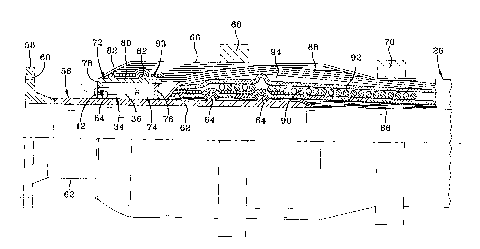
[0020] The hose 26 is configured having an inner carcass layer 86 fox
retaining a fluid
such as oil flowing through the hose 26. Pursuant to conventional construction
of double
carcass hose, an outer auxiliary carcass layer 88 surrounds the inner layer 86
and is
capable of retaining the fluid leaking through the inner layer 86. Tensile
reinforcement
members 90 are wound around the inner carcass 86, enclosed within cord layers
92. The
reinforcement structure represented by tensile members 90 and cord ply layers
92
provide structural strength to the fluid conveying inner carcass 86. A fluid-
tight
CA 02455363 2004-O1-16
buffering or collection space 94 is positioned between the inner carcass 86
and the outer
carcass 88 and extends the axial length of the hose 26. The space 94 receives
and retains
fluid leaking through the main inner carcass layer 86.
[0021] Pursuant to conventional practice, the flange 58 is inserted in one end
of the hose
body. The cord plies of 92 fit in spaces between the anchoring rings 64 to
fasten the
hose body to the flange S8. Similarly a cord ply layer 93 beneath the outer
carcass 88
fits in spaces between the anchoring rings 82. Thus attached, the forward end
of the hose
segment 26 is fixedly retained within the cylindrical body 66 and is
mechanically
secured thereto. The collection space 94, as shown in FIG. 5 extends forward
to the
annularly disposed and circurnferentially extending collection housing 72.
Apertures
through the rearward end wall 76 of the collection housing 72 allow fluid from
the
collection space 94 to migrate into the collection chamber 74. Accordingly,
the
collection chamber 74 is in fluid communication with the collection space 94
and fluid
leaking from inner carcass 86 will be collected within the collection chamber
74 of
housing 72.
[0022] The sensor 34 is assembled to the forward end wall 78 of the collection
housing
72 in the manner shown in FIG. 5. With combined reference to FIGS. 2, 3, and
5, the
sensor body 36 inserts through aperture 84 of end wall 78 and projects into
the collection
chamber 74. Threaded bolt end 42 secures the sensor 34 in a fixed, fluid tight
connection to the housing 72. The leads 44 exit from the rearward end of the
sensor 34
and may be directed to the oil platform or oil tanker control room. The
electro-optic
transmitter and receiver 38, 40 are thus positioned within the collection
chamber 74 at a
location generally proximate the rearward end wall 76.
[0023] It will be readily appreciated that the sensor 34 is consequently in
position to
sense fluid that escapes the inner hose carcass 86 into the collection space
94 and,
thence, migrates into the collection chamber 74. As the fluid enters the
chamber 74
through wall 76 it will penetrate into the gap 41 separating the transmitter
and receiver
38, 40 and interfere with the optical beam transmitted therebetween. The
blockage of the
beam by the oil will, as described previously, close the circuit and cause a
signal to be
transmitted to the control unit. The signal indicates a leak has occurred in
the hose
segment associated with the sensor. The signal preferably will be coded, or
the control
CA 02455363 2004-O1-16
-g_
unit will be wired, to identify the sensor from which the leak signal
originated. In this
manner, the leak can be quickly located and repairs or emergency procedures
immediately effected. The resin cover 46 over the forward end of the sensor 34
is liquid
tight and serves to prevent entry of oil from the collection chamber 74 into
the interior of
the sensor. The electronic circuitry within the sensor is thus insulated from
potentially
damaging contamination from the surrounding oil.
[0024] FIG. 4 illustrates a representative control panel 14 that may be
located in the
control room of a tanker or oil platform. The panel 14 may be wired with a
visual
display (for example, a LED) that indicates in general that a leak has
occurred. A bank
of visual indicators (LED's) 97 may further be provided and wired to indicate
the
particular sensor that has been activated by a leak. The location of the leak
may thus be
ascertained. In addition, an audible alarm set 98 may be provided to emit an
audible
sound when a leak is detected.
[0025] The sensor system described above satisfies the need of the industry
for a means
of detecting leakage in a submarine or floating hose line from a remote
location, twenty
four hours a day and every day of the year, irrespective of weather conditions
or lighting
conditions. A twenty-four hour operation of the pumping station is thereby
facilitated,
reducing tanker loading time and making the pumping operation more cost
effective.
Moreover, because leaks may be remotely detected electronically and monitored
from a
control room in the tanker or drilling platform, continuous inspection of the
oil lines by
divers is eliminated. Elimination of risky diving inspections not only reduces
the risk of
bodily injury to the divers but also significantly reduces operational costs
associated
therewith.
[0026] Alternative configurations of sensors, as explained previously, may be
substituted
for the electro-optic sensor described as the preferred embodiment. The
electro-optic
sensor is preferred because it is relatively simple and resistant to
malfunction or
breakage. An efficient energy efficient switching circuit may be employed that
issues a
leak signal when the beam of light is broken. Because the collection housing
72, sensor
34, and the collection chamber 74 are advantageously positioned relative to
the
collection space 94, there is a high probability that leaking fluid from the
inner carcass
will be detected and the sensor will issue a leak detection signal as
designed. The signal
CA 02455363 2004-O1-16
-9-
may be conducted to the control unit by hard wire or communicated in a
wireless manner
if preferred.
(0027] Variations in the present invention are possible in light of the
description of it
provided herein. While certain representative embodiments and details have
been shown
for the purpose of illustrating the subject invention, it will be apparent to
those skilled in
this art that various changes and modifications can be made therein without
departing
from the scope of the subject invention. It is, therefore, to be understood
that changes
can be made in the particular embodiments described which will be within the
full
intended scope of the invention as defined by the following appended claims.