Sélection de la langue

Search

Sommaire du brevet 2455373 

Énoncé de désistement de responsabilité concernant l'information provenant de tiers

Une partie des informations de ce site Web a été fournie par des sources externes. Le gouvernement du Canada n'assume aucune responsabilité concernant la précision, l'actualité ou la fiabilité des informations fournies par les sources externes. Les utilisateurs qui désirent employer cette information devraient consulter directement la source des informations. Le contenu fourni par les sources externes n'est pas assujetti aux exigences sur les langues officielles, la protection des renseignements personnels et l'accessibilité.

Disponibilité de l'Abrégé et des Revendications

L'apparition de différences dans le texte et l'image des Revendications et de l'Abrégé dépend du moment auquel le document est publié. Les textes des Revendications et de l'Abrégé sont affichés :

  • lorsque la demande peut être examinée par le public;
  • lorsque le brevet est émis (délivrance).
(12) Demande de brevet: (11) CA 2455373
(54) Titre français: ARMOIRE A SECHER LE LINGE A DISTRIBUTION D'AIR AMELIOREE
(54) Titre anglais: CLOTHES DRYING CABINET WITH IMPROVED AIR DISTRIBUTION
Statut: Réputée abandonnée et au-delà du délai pour le rétablissement - en attente de la réponse à l’avis de communication rejetée
Données bibliographiques
(51) Classification internationale des brevets (CIB):
  • D06F 58/10 (2006.01)
  • A47B 81/00 (2006.01)
  • D06F 71/34 (2006.01)
(72) Inventeurs :
  • PROWS, DENNIS S. (Etats-Unis d'Amérique)
(73) Titulaires :
  • MAYTAG CORPORATION
(71) Demandeurs :
  • MAYTAG CORPORATION (Etats-Unis d'Amérique)
(74) Agent: TORYS LLP
(74) Co-agent:
(45) Délivré:
(22) Date de dépôt: 2004-01-19
(41) Mise à la disponibilité du public: 2004-08-06
Requête d'examen: 2004-04-29
Licence disponible: S.O.
Cédé au domaine public: S.O.
(25) Langue des documents déposés: Anglais

Traité de coopération en matière de brevets (PCT): Non

(30) Données de priorité de la demande:
Numéro de la demande Pays / territoire Date
10/361,896 (Etats-Unis d'Amérique) 2003-02-06

Abrégés

Abrégé anglais


A clothes drying cabinet is provided with an internal compartment for
receiving
clothes and having a plurality of air inlet nozzles. An air plenum provides
air to the cabinet
through the nozzles. The plenum has a decreasing cross section from one corner
to an
opposite corner to provide a balanced distribution of air through the nozzles
at a
substantially uniform velocity. The nozzles are angularly oriented to direct
air across upper
and lower surfaces of shelves mounted within the drying compartment.

Revendications

Note : Les revendications sont présentées dans la langue officielle dans laquelle elles ont été soumises.


What is claimed is:
1. A cabinet for drying clothes, comprising: a compartment for receiving
clothes, and
having a plurality of air inlet holes; an air plenum for providing air to the
cabinet through
the air inlet holes; the plenum having a varying cross section to provide a
balanced
distribution of air through the inlet holes of the cabinet.
2. The cabinet of claim 1 wherein the compartment has opposite side walls
defining a
cabinet width and the plenum having a decreasing depth across the width of the
cabinet.
3. The cabinet of claim 1 wherein the compartment has a top wall and a bottom
wall
defining a cabinet height, the plenum having a decreasing depth along the
height of the
cabinet.
4. The cabinet of claim 1 wherein the compartment has a width defined by
opposite
side walls and a height defined by top and bottom walls, and the plenum has a
decreasing
depth across the width of the compartment and a decreasing depth along the
height of the
cabinet.
5. The cabinet of claim 1 further comprising a fan in communication with the
air
plenum for supplying air to the plenum.
6. The cabinet of claim 1 wherein the plenum has four corners, with an air
inlet in one
of the corners.
7. The cabinet of claim 1 wherein the plenum has a cross sectional area that
is reduced
from the air inlet corner to an opposite corner.
8. The cabinet of claim 7 wherein the cross sectional area of the plenum is
reduced in
a radial pattern.
6

9. The cabinet of claim 1 further comprising an air duct communicating with
the
plenum.
10. The cabinet of claim 9 wherein the cross sectional area of the plenum
reduces from
the air duct to the air inlet hole furthest from the air inlet.
11. A clothes drying cabinet comprising: a compartment having a front door,
opposite
side walls, a rear wall, a top wall and a bottom wall; one of the walls having
air inlet holes;
an air plenum behind the wall with the inlet holes; an air supply
communicating with the
air plenum; and the air plenum having a varying cross sectional area to
provide
substantially constant velocity of air distribution through the air inlet
holes to the
compartment.
12. The cabinet of claim 11 wherein the air supply includes a fan and an air
duct for
directing air from the fan to the air plenum.
13. The cabinet of claim 12 wherein the cross sectional area of the air plenum
decreases
with distance from the air duct.
14. The cabinet of claim 11 wherein the air plenum has a depth which decreases
laterally from one side wall to the other side wall.
15. The cabinet of claim 11 wherein the air plenum has a depth which decreases
vertically between the bottom and top walls.
16. The cabinet of claim 11 wherein the air plenum has a depth which decreases
laterally and vertically.
17. The cabinet of claim 11 wherein the plenum has four corners and the air
supply is
connected to one of the corners.
7

18. The cabinet of claim 17 wherein the plenum has a cross sectional area that
decreases from the corner with the air supply to an opposite corner.
19. The cabinet of claim 17 wherein the cross sectional area of the plenum
decreases
from the air supply corner in a radial pattern.
20. The cabinet of claim 11 wherein the plenum is defined by the rear wall of
the
compartment and a back panel mounted over the rear wall in spaced relation
thereto.
21. A cabinet for drying clothes, comprising: a compartment fox receiving
clothes, and
having a plurality of air inlet nozzles; an air plenum for directing air
through the nozzles
and into the cabinet; and the nozzles being angled in multiple directions to
direct air into
the compartment at multiple directions.
22. The cabinet of claim 21 wherein the nozzles include first and second sets,
with the
first set being directed upwardly and the second set being directed
downwardly.
23. The cabinet of claim 21 wherein the nozzles are arranged in a pattern to
alternate
the direction air is directed into the compartment.
24. The cabinet of claim 21 further comprising a plurality of shelves in the
compartment, and the nozzles direct air to upper and lower surfaces of each
shelf.
25. The cabinet of claim 21 wherein the nozzles include multiple columns which
alternately direct air upwardly and downwardly into the compartment.
26. The cabinet of claim 21 wherein the nozzles include multiple rows which
alternatingly direct air upwardly and downwardly into the compartment.
27. The cabinet of claim 21 wherein the compartment includes a rear wall with
the
nozzles located therein.
8

28. The cabinet of claim 21 wherein the nozzles are formed in the rear wall,
29. The cabinet of claim 21 wherein the nozzles are angled in non-horizontal
directions.
30. The cabinet of claim 21 wherein the nozzles are angled between 0-
45° with respect
to vertical.
31. The cabinet of claim 21 wherein the nozzles are in a pattern of rows and
columns
with adjacent rows and columns directing air in different directions into the
compartment.
32. A clothes drying cabinet, comprising: a compartment having a front door,
opposite
side walls, a rear wall, a top wall and a bottom wall; a first set of air
nozzles in one of the
walls of the compartment to direct air in a first direction into the
compartment; and a
second set of air nozzles in one of the walls of the compartment to direct air
in a second
direction into the compartment.
33. The cabinet of claim 32 wherein the first direction is upwardly.
34. The cabinet of claim 32 wherein the second direction is downwardly.
35. The cabinet of claim 32 wherein the first and second directions are non-
horizontal.
36. The cabinet of claim 32 wherein the first and second sets of nozzles are
arranged in
alternating columns.
37. The cabinet of claim 32 wherein the first and second sets of nozzles are
arranged in
alternating rows.
38. The cabinet of claim 32 wherein the nozzles are in the back wall.
9

39. The cabinet of claim 38 wherein the nozzles are integrally formed in the
back wall.
40. The cabinet of claim 32 further comprising a plurality of shelves mounted
in the
compartment.
41. The cabinet of claim 40 wherein the nozzles direct air across upper and
lower
surfaces of the shelves.
10

Description

Note : Les descriptions sont présentées dans la langue officielle dans laquelle elles ont été soumises.

CA 02455373 2004-O1-19
TITLE: CLOTHES DRYING CABINET WITH
IMPROVED AIR DISTRIBUTION
BACKGROUND OF THE INVENTION
Clothes drying cabinets, which are more common in Japan than in the United
States, are used for drying clothes without the conventional tumbling action.
As opposed
to a conventional tumbler dryer, a drying cabinet provides heated air for
drying clothes
hanging in the cabinet. Drying cabinets can also be used for de-wrinkling
clothes. The de-
wrinkling process includes the introduction of steam into the cabinet, which
facilitates the
removal of wrinkles from the clothes. The drying air is provided through
multiple holes or
louvers formed in one or more walls of the drying cabinet. However,
conventional drying
cabinets generally do not provide a balanced air flow through the cabinet,
since the velocity
of air flow through the inlet holes or louvers is greatest near the air supply
source and
progressively decreases as the inlet holes or louvers are spaced farther from
the air supply
source. Also, the drying air normally enters the cabinet through the holes or
louvers in a
common direction, which minimizes or reduces the mixture of drying air within
the
cabinet.
Conventional drying cabinets also do not have shelves for receiving clothes to
be
dried, such as sweaters which preferably should not be hung on a hanger,
particularly when
wet.
Accordingly, a primary objective of the present invention is the provision of
an
improved clothes drying cabinet.
Another objective of the present invention is the provision of an improved
clothes
drying cabinet having balanced air distribution throughout the cabinet.
A further objective of the present invention is the provision of an improved
clothes
drying cabinet wherein drying air is introduced through holes or nozzles in
the cabinet wall
at a substantially unifot-~n velocity.
Another objective of the present invention is the provision of an improved
clothes
drying cabinet wherein the drying air is introduced through a plurality of air
inlet holes or
nozzles at multiple non-horizontal angles.

CA 02455373 2004-O1-19
Another objective of the present invention is the provision of an improved
clothes
drying cabinet having shelves for drying clothes thereon, and with drying air
directed to
both the upper and lower surfaces of the shelves.
A further objective of the present invention is the provision of an improved
clothes
drying cabinet wherein an air plenum directs drying air into the cabinet
uniformly.
Another objective of the present invention is the provision of an improved
clothes
drying cabinet wherein an air distribution plenum has a decreasing cross
sectional area,
both horizontally and vertically, to provide substantially constant velocity
air flow into the
drying cabinet.
Another objective of the present invention is the provision of an improved
clothes
drying cabinet which also distributes steam in the cabinet for de-wrinkling
clothes.
These and other objectives of the present invention will be apparent from the
following description.
SUMMARY OF THE INVENTION
A clothes drying cabinet has a compartment with a front door or doors,
opposite
side walls, a rear wall, a top wall, and a bottom wall. A plurality of air
inlet holes or
nozzles are provided in one of the walls. An air plenum resides behind the air
nozzles to
distribute air from an air source through the nozzles and into the compartment
for drying
clothes therein. The air plenum has a cross sectional area which decreases
from the nozzles
closest to the air source to the nozzles furthest from the air source, so as
to provide a
substantially constant air flow velocity through the nozzles into the
compartment. The
nozzles are directed in an angular, non-horizontal orientation so as to
provide drying air in
multiple directions into the compartment. Mesh shelves may be provided in the
compartment, with the air being directed to both the upper and lower surfaces
of the
shelves to enhance drying of objects laid on the shelves.
BRIEF DESCRIPTION OF THE DRAWINGS
Figure 1 is a perspective view of a combination tumble dryer and drying
cabinet
with the front doors closed.
Figure 2 is a view similar to Figure 1 showing the front doors open.
2

CA 02455373 2004-O1-19
Figure 3 is a front perspective view of the drying cabinet liner.
Figure 4 is a rear perspective view of the cabinet dryer liner with the air
plenum
wall secured thereto.
Figure 5 is a front perspective view of the air plenum wall.
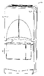
Figure 6 is a front elevation view of the air plenum wall.
Figure 7 is a sectional view taken along lines 7-7 of Figure 6.
Figure 8 is a front elevation view of the drying compartment of the drying
cabinet
of the present invention.
Figures 9A-9E are sectional views taken along lines 9A-9A through 9E-9E on
Figure 8.
Figure 10 is a front elevation view of the drying compartment of the present
invention.
Figures 11A-11E are sectional views taken along lines 11A-11A through 11E-11E
of Figure 10.
DETAILED DESCRIPTION OF THE INVENTION
Figure 1 shows a combination clothes drying machine 10 having a tumble dryer
12
and a drying cabinet 14. The drying cabinet 14 is shown to be mounted on top
of the
tumble dryer 12, though it is understood that other configurations can be
provided. The
tumble dryer 12 includes a door to provide access to the rotatable drum 18.
The drying cabinet 14 includes a pair of doors 20 which provide access to a
drying
compartment 22. As seen in Figure 2, the compartment 22 may include removable
shelves
24, which preferably have a mesh support surface so that air can circulate
therethrough.
The compartment 22 is formed by a liner 26, best shown in Figure 3. The liner
26
includes opposite side walls 28, 30, a rear wall 32, a top wall 34, and a
bottom wall 36.
The bottom wall 36 has a curved profile so as to extend around the drum 18 of
the tumble
dryer 12. The compartment 22 includes an elongated portion 38 adapted to
receive long
hanging items for drying, such as a dress.
A plurality of shelf supports 40 are formed on the wall 30. Shelf support rods
42
are removably mounted in the rear wall 32 of the liner 26. Thus, the shelves
24 can be
quickly and easily installed and removed with the opposite rigid sides of the
shelves being
3

CA 02455373 2004-O1-19
supported by the shelf supports 40 and shelf rods 42. It is understood that
other means may
be provided for supporting the shelves 24.
A plenum wall 44 is mounted on the exterior of the rear wall 32 of the liner
26.
The plenum wall 44 includes a perimeter flange 46. A seal (slot shown) is
provided
between the perimeter flange 46 and the rear wall 32 of the liner 26.
The plenum wall 44 includes a lower portion 48 adapted to be connected to an
air
duct {not shown). The air duct conveys air from an air source, such as a fan,
to the air
plenum 50 defined by the space between the plenum wall 44 and the rear wall
32. The air
may be heated to enhance drying and may carry steam to enhance de-wrinkling of
clothes
within the drying cabinet 14.
As seen in Figures 8 and 9A-9E, the cross sectional area of the plenum 50
decreases
across the width of the plenum 50, with the greatest cross sectional area
being adjacent the
lower portion 48. Similarly, as shown in Figures 10 and 1 lA-11E, the cross
sectional area
of the plenum 50 decreases vertically from bottom to top, with the greatest
cross sectional
area being adjacent the lower portion 48 of the plenum wall 44. Thus, the
plenum 50 has
the greatest cross sectional area in the lower right corner, as shown in the
drawings
adjacent the introduction of air from the air inlet portion 48 and has the
smallest cross
sectional area in the opposite (upper left) corner furthest away from the air
inlet portion 48.
This gradual decrease in the depth of the plenum 50 in a radial pattern allows
the air to be
distributed through a plurality of air inlet holes or nozzles 52, 54 in the
rear wall 32 of the
compartment 22 at a substantially constant or uniform velocity. Thus, the air
distribution
through the nozzles 52, 54 is balanced across the rear of the compartment 22.
As seen in Figures 8 and 10, the nozzles 52, 54 are arranged in rows and
columns.
The nozzles 52, 54 are formed in the rear wall 32 of the compartment 22 and
are angularly
disposed, as best seen in Figures 9A-9E. More particularly, the nozzles 52 are
directed
downwardly, as seen in Figures 9A, 9C and 9E, while the nozzles 54 are
directed upwardly,
as seen in Figures 9B and 9D. Thus, when the shelves 24 are installed in the
compartment
22, the nozzles 52 direct air over the top surface of the shelves 24 while the
nozzles 54
direct air across the lower surface of the shelves 24. Since the shelf surface
is made of a
mesh material, drying of a sweater or other object placed upon the shelf 24 is
optimized by
the flow of air across the upper and lower sides of the object. Preferably,
the air from the
4

CA 02455373 2004-O1-19
nozzles 52, 54 should be directed toward the shelves 24 as much as possible
for optimal
drying performance, as opposed to horizontally across the shelves 24.
Therefore, the
preferred angle of the nozzles 52, 54 is 0-45° with respect to
vertical.
The preferred embodiment of the present invention has been set forth in the
drawings, specification, and although specific terms are employed, these are
used in a
generic or descriptive sense only and are not used for purposes of limitation.
Changes in
the form and proportion of parts as well as in the substitution of equivalents
are
contemplated as circumstances may suggest or render expedient without
departing from the
spirit and scope of the invention as further defined in the following claims.

Dessin représentatif
Une figure unique qui représente un dessin illustrant l'invention.
États administratifs

2024-08-01 : Dans le cadre de la transition vers les Brevets de nouvelle génération (BNG), la base de données sur les brevets canadiens (BDBC) contient désormais un Historique d'événement plus détaillé, qui reproduit le Journal des événements de notre nouvelle solution interne.

Veuillez noter que les événements débutant par « Inactive : » se réfèrent à des événements qui ne sont plus utilisés dans notre nouvelle solution interne.

Pour une meilleure compréhension de l'état de la demande ou brevet qui figure sur cette page, la rubrique Mise en garde , et les descriptions de Brevet , Historique d'événement , Taxes périodiques et Historique des paiements devraient être consultées.

Historique d'événement

Description Date
Exigences relatives à la nomination d'un agent - jugée conforme 2022-02-03
Exigences relatives à la révocation de la nomination d'un agent - jugée conforme 2022-02-03
Demande non rétablie avant l'échéance 2008-01-21
Le délai pour l'annulation est expiré 2008-01-21
Réputée abandonnée - omission de répondre à un avis sur les taxes pour le maintien en état 2007-01-19
Modification reçue - modification volontaire 2006-09-18
Inactive : Dem. de l'examinateur par.30(2) Règles 2006-03-23
Inactive : CIB de MCD 2006-03-12
Inactive : Demande ad hoc documentée 2004-09-14
Modification reçue - modification volontaire 2004-08-12
Demande publiée (accessible au public) 2004-08-06
Inactive : Page couverture publiée 2004-08-05
Lettre envoyée 2004-05-21
Toutes les exigences pour l'examen - jugée conforme 2004-04-29
Exigences pour une requête d'examen - jugée conforme 2004-04-29
Requête d'examen reçue 2004-04-29
Inactive : CIB attribuée 2004-04-28
Inactive : CIB en 1re position 2004-04-28
Inactive : Certificat de dépôt - Sans RE (Anglais) 2004-02-26
Lettre envoyée 2004-02-26
Demande reçue - nationale ordinaire 2004-02-26

Historique d'abandonnement

Date d'abandonnement Raison Date de rétablissement
2007-01-19

Taxes périodiques

Le dernier paiement a été reçu le 2005-12-13

Avis : Si le paiement en totalité n'a pas été reçu au plus tard à la date indiquée, une taxe supplémentaire peut être imposée, soit une des taxes suivantes :

  • taxe de rétablissement ;
  • taxe pour paiement en souffrance ; ou
  • taxe additionnelle pour le renversement d'une péremption réputée.

Les taxes sur les brevets sont ajustées au 1er janvier de chaque année. Les montants ci-dessus sont les montants actuels s'ils sont reçus au plus tard le 31 décembre de l'année en cours.
Veuillez vous référer à la page web des taxes sur les brevets de l'OPIC pour voir tous les montants actuels des taxes.

Historique des taxes

Type de taxes Anniversaire Échéance Date payée
Enregistrement d'un document 2004-01-19
Taxe pour le dépôt - générale 2004-01-19
Requête d'examen - générale 2004-04-29
TM (demande, 2e anniv.) - générale 02 2006-01-19 2005-12-13
Titulaires au dossier

Les titulaires actuels et antérieures au dossier sont affichés en ordre alphabétique.

Titulaires actuels au dossier
MAYTAG CORPORATION
Titulaires antérieures au dossier
DENNIS S. PROWS
Les propriétaires antérieurs qui ne figurent pas dans la liste des « Propriétaires au dossier » apparaîtront dans d'autres documents au dossier.
Documents

Pour visionner les fichiers sélectionnés, entrer le code reCAPTCHA :


Pour visualiser une image, cliquer sur un lien dans la colonne description du document (Temporairement non-disponible). Pour télécharger l'image (les images), cliquer l'une ou plusieurs cases à cocher dans la première colonne et ensuite cliquer sur le bouton "Télécharger sélection en format PDF (archive Zip)" ou le bouton "Télécharger sélection (en un fichier PDF fusionné)".

Liste des documents de brevet publiés et non publiés sur la BDBC .

Si vous avez des difficultés à accéder au contenu, veuillez communiquer avec le Centre de services à la clientèle au 1-866-997-1936, ou envoyer un courriel au Centre de service à la clientèle de l'OPIC.

({010=Tous les documents, 020=Au moment du dépôt, 030=Au moment de la mise à la disponibilité du public, 040=À la délivrance, 050=Examen, 060=Correspondance reçue, 070=Divers, 080=Correspondance envoyée, 090=Paiement})


Description du
Document 
Date
(aaaa-mm-jj) 
Nombre de pages   Taille de l'image (Ko) 
Dessins 2004-01-18 10 354
Abrégé 2004-01-18 1 15
Description 2004-01-18 5 240
Revendications 2004-01-18 5 155
Dessin représentatif 2004-05-04 1 10
Revendications 2006-09-17 5 154
Courtoisie - Certificat d'enregistrement (document(s) connexe(s)) 2004-02-25 1 107
Certificat de dépôt (anglais) 2004-02-25 1 160
Accusé de réception de la requête d'examen 2004-05-20 1 176
Rappel de taxe de maintien due 2005-09-19 1 110
Courtoisie - Lettre d'abandon (taxe de maintien en état) 2007-03-18 1 175
Taxes 2005-12-12 1 30