Note : Les descriptions sont présentées dans la langue officielle dans laquelle elles ont été soumises.
CA 02455657 2007-02-27
SHAKING INCUBATOR
The invention relates to a shaking incubator with at least one specimen
storage device
comprising several superposed specimen stoi-age spaces.
In the present context, the term "specimen storage device" denotes a device
that can
receive specimens in several specimen storage spaces superposed like a tower.
In the
following, the tertn "speciniens" means open dishes, closed containers, so-
called microtiter
plates. and similar containers for receiving speciniens. These specimens are
frequently used
in research and industrial production in particular.
Shaking incubators are basically known froin the literature. Thus, European
Patent
Application EP 0569214 A2 discloses a shaker/incubator comprising an even
number of
shaking planes arranged like a tower that can be caused to shake by an
eccentric drive. The
~i~*T~ificant d;sadv'a;:t~na of this dev:ce is tliat ali siial ., ' 1.. 1~
, b.. .b. ..nb piu~~w are iiw'veu SiT1'iii~iuneoiis~y uy
a common eccentric drive. Thus, it is impossible to niove individual
superposed shaking
planes while other shaking planes of the to~.ver ai-e at rest. Also, the
eccentric drive permits
only the same intensity of shaking movement for all shaking planes of the
tower.
The invention therefore is based on the problein of specifying a shaking
incubator of
the initially mentioned type that makes it possible to shake the specimens
located in a
specimen storage device individually and independently of each other.
This problem is solved for an initially characterized shaking incubator in
that a
shaking unit comprising:
at least two specimen storage spaces, wherein the specimen storage
spaces are arranged in a tower shape and are capable of agitated individually
and independently of each other, wherein the specimen storage space
comprising a specimen storage position, a shaking platform, and a base unit.
The shaking unit arranged at a specimen storage space of a specimen storage
device
permits a specimen located at the specimen storage position.of the shaking
unit to be shaken
individually according to a fixed motion sequence. If a shaking unit is
arranged in several
specimen storage spaces of a specimen storaae device, the specimens located at
the specimen
storage positions of the shaking units can be agitated independently of each
other according
to a motion sequence deterinined individually for each specimen.
In a first pi-eferred embodiment of the invention, the base unit of the at
least one
shaking unit is pernianently connected to the specimen storage device. This
assures on the
one hand a permanent and especially stable fastenin- to the specimen storage
device, and
produces on the other hand an additional stabilization of the specimen storage
device.
On the otlier hand, an alternative pi-efci-i-ed fui-ther development provides
a detachable
1
CA 02455657 2007-02-27
holder for the at least one shaking unit of a specimen storage device in a
specimen storage
space so that the shaking unit can be removed as required from the specimen
storage device.
Basically, all detachable holders known in the prior art can be considered.
For example, the
1a
CA 02455657 2004-01-22
shaking unit can be held on the specimen storage device, by two rails and
sliding of the
shaking unit can be prevented by a detachable snap connection.
In addition, it is advantageously provided that the specimen storage positions
for the
at least one shaking unit be designed such that a specimen can be supplied by
an automated
transport system, and a specimen can be removed from the specimen storage
position by an
automated transport system.
To this end, a preferred embodiment provides for the specimen storage position
of the
at least one shaking unit to comprise a spacer element arranged on the shaking
platform
which creates free space for manipulating a specimen located at the specimen
storage
position. The spacer element can have basically all forms known to a person
skilled in the art.
For example, a one-part, U-shaped spacer element or a spacer element
consisting of two parts
would be suitable. In both instances the spacer element is arranged on the
shaking platform
such that a specimen held on the bottom by a transport device can be placed
without
difficulty in the specimen storage position, and that the transport device can
again be
withdrawn.
It is also advantageous for the specimen storage position of a shaking unit to
comprise
at least one clamping element arranged on the shaking platform or on the
spacer element. A
specimen located in the specimen storage position can in this way be
effectively prevented
from sliding. The clamping element can be single or multi-part. For example,
four fixing
brackets at the corners of the specimen storage position are suitable for a
multi-part clamping
element.
In another preferred embodiment, a control unit for controlling and supplying
current
to the at least one shaking unit is arranged outside of the incubator
workspace, with a
control/supply line running from this control unit into the incubator
workspace, said line
having a line connector in the incubator workspace. The control unit comprises
the
components, known to a person skilled in the art, that are necessary to assure
the current
supply as well as the control of the at least one shaking unit in the
incubator workspace.
Thus, the control unit can comprise, e.g., a calculating unit by means of
which the motion
sequence of the shaking platform of a shaking unit is fixed.
The at least one shaking unit is advantageously connected via a detachable
line
connection to the line connector of the at least one control unit. A person
skilled in the art is
familiar with the various detachable line connections that can be used here.
In another preferred embodiment, a distributor unit for connecting several
shaking
units is arranged in the incubator workspace and is connected via a detachable
line
connection to the line connector of the at least one control unit. The
distributor unit can be
permanent or detachable, e.g., held on the wall of the incubator workspace.
The line
connector of the shaking units on the distributor unit can be permanent or
detachable,
according to the prior art. A detachable line connector between the shaking
unit and the
2
CA 02455657 2004-01-22
distributor unit is particularly appropriate when the shaking unit is to be
removed as required
from the specimen storage device.
An alternative preferred refinement provides for arranging a distributor unit
on a
specimen storage device. This minimizes the line length from the at least one
shaking unit
located in the specimen storage device to the distributor unit, and creates
the possibility of
replacing a specimen storage device rapidly and simply with another specimen
storage device
containing, e.g., a different number of shaking units in the specimen storage
device. A
replacement of the entire specimen storage device is advantageous, e.g., when
the height of
the specimens to be stored makes it necessary to change the number of specimen
storage
spaces present in a specimen storage device.
However, it can also be especially advantageous to arrange a distributor unit
on
several specimen storage devices for the connection of several shaking units.
In particular,
when numerous shaking units are present in several specimen storage devices,
the line length
from a shaking unit to the next distributor unit is kept as small as possible,
and in addition it
becomes more convenient to replace individual specimen storage devices.
Moreover, a preferred refinement provides for using of a shaking unit in which
the
shaking platform is positioned automatically in a central zero position after
the current has
been turned off. As a result, a specimen located on the shaking platform is
brought into a
central and horizontal position after the end of the shaking procedure, this
being is a
prerequisite for automated supply to and removal from the specimen storage
position by a
transport device.
Finally, an especially advantageous embodiment provides for a shaking unit to
be
arranged in several specimen storage spaces, and for the shaking platforms of
these shaking
units to be controllable individually and independently of each other by the
at least one
control unit. "Individually and independently of each other" in this context
means that the
shaking movement, that is, e.g., the shaking frequency or the amplitude
(shaking level), can
be set and controlled for each individual shaking platform by the at least one
control unit.
This makes it possible to supply a specimen storage device with different
specimens and to
move them according to their individual requirements as regards shaking
movement and
shaking duration. If a shaking movement is not intended for a specimen, the
specimen storage
space of the shaking unit functions as a static storage space on account of
the resting shaking
platform. The person skilled in the art is familiar with numerous applications
in which a
specimen must be alternately shaken and stored, under incubation conditions,
in a
chronological sequence. Consequently, the invention creates the possibility of
introducing
several specimens by an automated transport system in a chronologically
staggered manner
into one and the same specimen storage device, and of shaking and storing the
specimens
under incubation conditions according to an individual program.
CA 02455657 2004-01-22
The invention is described in detail in the following using an embodiment, and
making reference to two drawings.
Figure 1 shows an oblique rear view of a prefeiTed embodiment of the
invention.
Figure 2 shows a of the preferred embodiment of specimen storage device
according
to Figure 1.
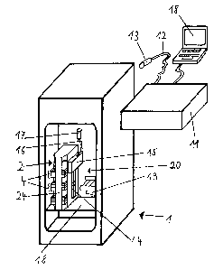
Figure 1 shows a shaking incubator 1 whose incubator workspace 20 can be
viewed
through the rear wall/door (not shown). Specimen storage device 2 comprising
several
superposed specimen storage spaces 3 (see Figure 2) is shown in incubator
workspace 20. A
shaking unit 4 is arranged in each specimen storage space of illustrated
specimen storage
device 2. Shaking units 4 are connected to distributor unit 15 via line
connections (not
visible) located behind cover 14.
For its part, distributor unit 15 is detachably connected via line connection
16 and line
connector 17 to line connector 13 of control/supply line 12 of control unit
11. In the present
embodiment, control unit 11 comprises computer unit 18 that determines the
shaking
movement of shaking platform 6 of a shaking unit 4 located in specimen storage
device 2.
The communication of computer unit 18 with the other components of control
unit 11 takes
place in the present example via an RS282 interface. However, a person skilled
in the art is
basically familiar with other interfaces for this purpose.
Shaking incubator 1 shown in Figure 1 comprises only one specimen storage
device 2
that is arranged on mounting plate 18 in incubator workspace 20. However, a
person skilled
in the art is also familiar with arrangements of several specimen storage
devices 2, also
including a carousel-like arrangement like the one disclosed in WO 98/05753.
Device 19, partially shown, in incubator workspace 20 is a transport system
known
from the prior art, e.g., WO 98/05753. Specimens 10 can be moved with
transport system 19
to the individual specimen storage spaces 3 of a specimen storage device 2 and
placed there
in a specimen storage position 5 (see Figure 2). In a corresponding manner, a
specimen 10 is
removed again, as required, by transport system 19 from specimen storage
position 5.
According to the invention, the use of transport system 19 in the arranging of
one or more
shaking units 4 in specimen storage device 2 makes it possible to unite in a
single incubator
the advantages of automatic loading and unloading of specimen storage position
5 with
specimens 10, and of automatic shaking of specimens 10.
Figure 2 shows a front view of a specimen storage device 2 in which a shaking
unit 4
is arranged according to the invention in on at least one specimen storage
space 3. The
specimen storage device consists substantially of a tower-shaped construction
with two side
walls 21, cover plate 22 and bottom plate 23. Specimen storage device 2 is
positioned reliably
and protected against any sliding on mounting plate 18 with the aid of a
centering opening
4
CA 02455657 2004-01-22
(not shown) located in bottom plate 23 and with the aid of a centering strip
(not shown)
attached to mounting plate 18, this strip positively cooperating with the
centering opening. In
addition, specimen storage device 2 can comprise rear wall 24, as shown in
Figure 1, that
imparts additional stability to the specimen storage device.
Typically, four to six shaking units 4 can be ai-ranged in a specimen storage
device 2,
depending on the space requirement of the specimens to be stored. A shaking
unit 4
comprises a specimen storage position 5, sllaking platform 6, and base unit 7.
As in the
present embodiment, sliding of specimen 10 is effectively prevented by
clamping elements 9.
In the present instance, these elements are designed as fixing brackets at the
four corners of
specimen storage position 5. As can be seen from Figure 2, specimen storage
position 5 also
comprises spacer element 8. This spacer element is arranged on shaking
platform 6 and is
designed such that transport system 19, holding specimen 10 from below, can
place it onto a
specimen storage position 5 and remove it again as required. In the case of a
differently
designed transport system that holds speciinen 10, e.g., by its top, spacer
elements 8 are not
required. As Figure 2 shows, specimen 10, clamping element 9 and spacer
element 8 are
arranged on shaking platform 6. That is, specimen 10 is moved together with
specimen
storage position 5 by shaking platform 6. The shaking movement of shaking
platform 6 is
produced by base unit 7 on which shaking platform 6 is arranged. Base unit 7
can be
permanently connected to specimen storage device 2, as represented in the
present
embodiment, which results in additional stabilization of specimen storage
device 2.
A specimen 10, shown in Figure 2, is arranged together with clamping elements
9 and
spacer element 8 on shaking platform 6 that is aligned relative to base unit 7
in a centered and
parallel manner, that is, horizontally. Positioning of shaking platform 6 to a
central zero
position after the current has been turned off takes place automatically and
without further
external intervention. As a result, a specimen 10 comes to rest in a defined
spatial position
after the current has been turned off, without shaking platform 6 requiring a
elaborate
electrical tracking. A precisely known spatial position is necessary in order
for automated
transport system 19 to be able to take a specinien 10 from a specimen storage
position 5 or
place it in a specimen storage position 5.
Shaking units 4 of specimen storage device 2 shown in Figure 2 are connected
via line
connections located under cover 14 to distributor unit 15 arranged on side
wall 21 of
specimen storage device 2. Distributor device 15 is connected by line
connector 17 to line
connector 13 of control unit 11. Thus, in the present embodiment all shaking
units 4 located
on the illustrated specimen storage device 2 are connected via only one
detachable line
coniiector 17 to control unit 11 serving for control and current supply.
As can be seen from Figure 2, the interval between shaking units 4 located in
specimen storage device 2 is selected such that specimens 10 even higher than
the ones
illustrated can be shaken. Concretely spe.akiiig, this means that in addition
to the illustrated
CA 02455657 2004-01-22
specimens 10 with a height of approximately 25 mm, even specimens up to a
height of
approximately 55 mm can be shaken. Since tiie height of shaking units 4 is
known, and in the
present embodiment is approximately 45 min, it is possible at any time, using
the
aforementioned dimension data, to change the number of shaking units 4 in
specimen storage
device 2 so as to satisfy the particular requirements.
6