Note : Les descriptions sont présentées dans la langue officielle dans laquelle elles ont été soumises.
CA 02456088 2004-02-18
A LONG TRACK MOUNTAIN SNOWMOBILE
AND TRACK THEREFOR
BACKGROUND OF THE INVENTION
Field of the Invention
This invention relates to a snowmobile with a long track designed to provide
improved
traction and smoother ride in light or powder snow. Further, the present
invention concerns a
new tread pattern of a snowmobile drive track wherein, among others, the track
provides superior
flotation and traction while maintaining an acceptable degree of
maneuverability compared to the
conventional track tread patterns in light or powder snow.
2. Description of Related Art
Given the popularity of snowmobiles nowadays, snowmobile manufacturers are
offering
increasingly diverse choices of snowmobiles adapted for use in different
environments.
Examples of various categories of snowmobiles include, inter alia, high-
performance
snowmobiles, touring snowmobiles, utility snowmobiles, and mountain
snowmobiles. The
mountain snowmobiles, in particular, are designed to meet the unique demands
required by the
driving conditions in both the mountains and the trails. Such driving
conditions include climbing
hills, maneuvering sharp turns around trees, and riding on deep powder snow.
Hill climbing refers to driving a snowmobile up the slopes of the mountains.
This task
requires that the track of the sled to provide greater traction than as would
be provided by the
CA 02456088 2004-02-18
tracks for flatland snowmobiles. More specifically, when climbing hills or
sidehilling, the
mountain sled is driven in a crisscrossing fashion, substantially upwardly in
diagonal directions
of the hills, intermittently reversing the lateral direction of the travel.
During this operation, the
weight of the sled plus the driver is shifted substantially from one lateral
side to another, and the
sled may be operating substantially leaning on one side. Such sidehilling
maneuvers require the
snow engaging lugs of both lateral sides of the track to provide substantially
more traction than
the flatland counterparts. To provide more traction force than the flatland
snowmobiles, the
mountain snowmobiles typically use longer tracks which have snow engaging
lugs, with higher
heights. Accordingly, where the typical height of the snow engaging lugs for
the tracks of
flatland snowmobiles is less than about 1 inches, the height of the snow
engaging lugs for the
mountain snowmobiles is greater than about 11/a inches, preferably in the
range of about 13/4
inches to 2 inches.
Acceptable maneuverability of the snowmobiles during sharp turns is another
key
ingredient of a mountain snowmobile. Driving the snowmobiles in the mountains
frequently
requires making turns, particularly in heavily wooded areas, and the mountain
snowmobiles
should be designed to maintain the steerability of the sleds. While the
increased traction force
provided by the tracks with higher heights of the snow engaging lugs and the
longer nominal
length provides improved traction in hill climbing, such tracks tend to propel
or "push" the sleds
too much, thereby overwhelming the mountain snowmobile's steerability. One
skilled in the art
describes this excessive "pushing" as the sled being "too wheely" or having
too "much rubber."
One way the industry has attempted to deal with the concerns over pushing is
by
providing narrower ski stance for mountain snowmobiles than flatland
snowmobiles, since
narrowing ski stance generally tends to enhance the steerability of the sleds.
Accordingly, a
2
CA 02456088 2004-02-18
typical mountain sled is equipped with skis whose ski stance is in a range of
about 37 inches to
39 inches, compared to the range of about 40 to 43 inches in the typical
flatland snowmobiles.
Finally, flotation refers to the ability of the snowmobiles to stay "afloat"
the terrain
comprising mainly of fresh powdery snow. In contrast to the flatland trails
where there is
typically light snow on the ground, in the mountains, there may be hills and
terrain which may be
covered by as much as 5 to 6 feet of powdery snow. The design of the mountain
snowmobiles
must provide sufficient flotation on the powder snow as the sled is being
driven on such hills and
terrain. Typically, the floatability of a snowmobile is a function of many
factors that includes the
overall weight of the sleds and the overall surface area of the track
contacting the snow surface.
Thus, conventional mountain sleds utilize "regular" tracks having a length of
136 inches
to provide more snow contacting surface in comparison to the flatland sleds
which generally
favor the use of "short" tracks having a length of 121 inches. One notable
exception of flatland
snowmobile having a track length greater than the 121 inch short track length
is the utility
snowmobile which may have a track longer than 136 inches, 156 inches for
example. One of the
key differences between a mountain snowmobile and a utility snowmobile, of
course, lies in the
height of the snow engaging lugs, which is substantially greater in tracks for
the mountain sleds.
Notwithstanding the foregoing, many in the industry, until recently, used to
hold the view
that apart from the differences in the ski stance and the track length, the
mountain snowmobiles
are little different from the flatland snowmobiles. In the last few years,
however, snowmobile
manufacturers have devoted considerable attention to the mountain snowmobiles
to satisfy the
special requirements for use in the mountains.
There are several dimensional features of mountain snowmobiles that have been,
by in
large, constant and unchanging due to the requirements imposed by the specific
driving
3
CA 02456088 2004-02-18
conditions in the mountain applications. One of such dimensions is the
aforementioned ski
stance which is typically in a range of about 37 inches to 39 inches. Another
of such dimensions
is the length of the tracks for the mountain snowmobiles, which has been fixed
at length of 136
inches. All mountain snowmobile made available by the snowmobile manufacturers
heretofore
have been made to use tracks having a length of 136 inches and no greater. If
the end users
wanted more traction or more snow contracting track surface, they needed to
purchase an
aftermarket track having a length of 141 inches and install using a bracket
kit to accommodate
the added length of 5 inches in the track.
The industry's adherence to a fixed track length of 136 inches reflects the
magnitude of
its concerns over "pushing." Although greater traction and better flotation
may have been
achievable by lengthening the track length, those skilled in the art, however,
have been reluctant
to increase the length of the tracks for the snowmobiles. Many in the industry
have been openly
skeptical about whether mountain sleds having a track with a longer length
than the industry
standard 136 inches would properly function in mountain applications which
also require an
effective, satisfactory maneuverability. Such skepticism seemingly commanded
much support
from those skilled in the art, particularly in light of the fact that the snow
engaging lugs have a
height of about 1 %4 to 2 inches. Although these gnarly lugs provide the
necessary traction force
to climb hills or to keep the sled moving in the deep powder snow, they run
the risk of providing
too great a traction force. The prevalent view in the industry was that the
extra snow engaging
lugs in combination with the increased track length would produce too much
traction force and
that the mountain sled would begin to loose steerability to negotiate around
turns, because such
"long length" tracks would push the mountain sled too much.
4
CA 02456088 2004-02-18
Largely because these concerns over "pushing" and "turning out," one skilled
in the art
could not and did not change the length of the track, despite potential
superior performance of
the longer tracks in hill climbing capabilities and flotation. Indeed, such
proclivity of the
industry is evidenced by the fact that no major commercial manufacturer known
to the applicants
has made available a mountain snowmobile having a track whose length is
greater than 136
inches. Further, even in the aftermaket, no track for mountain snowmobiles has
a length greater
than 141 inches prior to the present invention.
In efforts to improve upon the currently available mountain snowmobiles, the
inventors
desired to provide a track whose length is greater than the standard 136
inches and the 141
inches available in the aftermarket. While many in the industry have remained
skeptical about
using long tracks in mountain snowmobiles, the inventors determined that one
of the avenues
which could overcome the challenges of using the long tracks in mountain
snowmobiles is to
improve the tread patterns of the tracks. In particular, the inventors of the
present invention
focused on the relationship between the tread patterns and the nominal length
of the tracks with
respect to traction, maneuverability, and flotation.
As would be understood by one skilled in the art, a pitch is a traverse row
along
reinforcing means provided in the track. A particular arrangements of lugs on
a pitch is defined
herein as a pitch pattern. An arrangement of pitch patterns over a
predetermined number of
successive pitches is defined herein as a tread pattern, which repeated
identically on the track on
successive pitches. The arrangement of the tread patterns over the entire
longitudinal length of
the track is defined as a track pattern.
Significant research efforts have been devoted to improving and optimizing the
characteristics of the tracks for snowmobiles, examples of which include:
tread patterns
5
CA 02456088 2004-02-18
disclosed in U.S. Pat. No. 5,713,645 to Thornpson et al., and the tread
pattern shown in FIG. 12,
manufactured by Camoplast Inc. of Sherbrooke, Canada, Track Number 570-2109
and marketed
by Bombardier Inc. of Montreal Canada as the track for a snowmobile under the
trademark SKI-
DOO, model 2000 Summit 700, model year 1999, shown in FIG. 11. While these
noted
examples provide effective traction and control of the snowmobile in many
applications, the
inventors of the present invention have found that still further improvements
can be made in
optimizing and improving the performance of the tracks, in particular for
tracks for use on light
or powder snow.
With the existing track profile configurations, when the snowmobile is
operating on soft
or powder snow, when there is increased traction force, the tracks may tend to
simply dig a hole
in the snow rather than propelling the sled in the driving direction. That is,
given the state of the
modern day high powered snowmobiles, under certain circumstances, the tracks
with the existing
track patterns would provide too much traction force vis-a-vis the
steerability of the sleds, i.e.,
"too much rubber." The most clear example of this shortcoming of the existing
track
configurations is evident when one attempts to use a long length track in a
mountain snowmobile
with the conventional track pattern.
As discussed earlier, mountain snowmobiles require the height of the lugs
formed on the
exterior surface of the track to be at least about 11/4 inches. The current
trend is to provide 2-inch
or 13/4 inch lugs for tracks for premium quality mountain snowmobiles. At the
same time, when
the inventors attempted increasing the traction force provided to the
snowmobile by lengthening
the nominal length of the track from the regular length of 136 inches to 151
inches, the traction
force became too large for the snowmobile to maintain its steerability. Thus
the requisite
maneuverability of the snowmobile necessary in negotiating turns in the
mountains was lost.
6
CA 02456088 2004-02-18
Thus, the inventors sought a novel track pattern which can advantageously
improve the
performance of a snowmobile on powder snow. This novel track would also enable
the inventors
to provide a mountain snowmobile having a long track whose length is greater
than 136 inches,
which is what the snowmobile manufacturers use, and also greater than 141
inches, which is
what aftermarket track manufacturers make available. In that process, the
inventors have further
found that the novel track pattern surprisingly provides better track
performance not only in the
mountain snowmobiles, but also other types of snowmobiles, such as flatland
snowmobiles.
SUMMARY OF THE INVENTION
Therefore, an object of the present invention is to provide a mountain
snowmobile with a
track having a length of greater than 141 inches. Another object of the
present invention to
provide a novel track for a snowmobile with improved track performance
characteristics, such as
traction, control and flotation.
BRIEF DESCRIPTION OF THE DRAWINGS
FIG. 1A is a side perspective view of a mountain snowmobile in the prior art,
manufactured by Bombardier Inc. of Montreal Canada under tl~e trademark SKI-
DOO, model
Summit 700, model year 1999;
FIG. 1B is a top view ofthe mountain mobile shown in FIG. 1A;
FIG. 2A is a side perspective view of an embodiment of a snowmobile in
accordance
with the present invention;
FIG. 2B is a top view of the mountain mobile shown in FIG. 2A;
7
CA 02456088 2004-02-18
FIG. 3 is a top perspective view of a portion of a snowmobile track
illustrating a tread
pattern in accordance with the present invention;
FIG. 4 is a side view of the portion of a snowmobile track illustrated in FIG.
3, taken
along line IV-IV, viewed in the longitudinal direction of the tarack, wherein
only the first pitch is
illustrated;
FIG. 5A is a sectional view of one of the projecting profiles of the portion
of a
snowmobile track illustrated in FIG. 3, taken along line V-V, viewed in the
transverse direction
of the portion of a track illustrated in FIG. 3;
FIG. 5B is a sectional view of an exemplary projecting profile similar to one
shown in
FIG. 5A except that the profile in FIG. 5B is provided with a metal clip for
engagement with the
driving means of the snowmobile.
FIG. 6 is a sectioned view of the portion of a snowmobile track illustrated in
FIG. 3,
taken along line VI-VI, viewed in the transverse direction of the track;
FIG. 7 is an isometric view of the portion of a snowmobile track illustrated
in FIG. 3;
FIG. 8 is a partially sectioned side view comparing a suspension system,
frame, tunnel,
and tunnel extension of the mountain snowmobile illustrated in FIG. 2A with
the a suspension
system, frame, and tunnel of the snowmobile illustrated in FIG. 1A;
FIG. 9A is a partially sectioned side view comparing a suspension system,
frame, tunnel,
and tunnel extension of the snowmobile according to the present invention
illustrated in FIG. 2A;
FIG. 9B is a partially sectioned side view comparing a suspension system,
frame and
tunnel of a snowmobile in the prior art illustrated in FIG. 1A;
FIG. 1 OA is an isometric view of the tunnel with the tunnel extension in
accordance with
an aspect of the present invention;
8
CA 02456088 2004-02-18
FIG. 1 OB is another isometric view of the tunnel with the tunnel extension
illustrated in
FIG. 10A viewed from another angle;
FIG. 11 is a perspective view of a portion of a snowmobile track bearing a
tread pattern
in the prior art; and
FIG. 12 is a perspective view of a portion of a snowmobile track bearing
another tread
pattern in the prior art.
DETAILED DESCRIPTION OF
EXEMPLARY EMBODIMENTS
Throughout the description of the various embodiments of the present
invention,
reference will be made to various elements, the construction of which is
readily known to those
skilled in the art. Accordingly, an exhaustive description of each and every
component is not
provided, only a description of those elements required for an understanding
of the present
invention.
FIGS. 1A and 1B illustrate a prior art mountain snowmobile 10 (that sold by
Bombardier
Inc. of Montreal, Canada, under the trademark SKI-DOO, model Summit 700, model
year 1999),
which has a forward end 11 and a rearward end 13 (that are defined
consistently with the travel
direction of the vehicle). The conventional snowmobile 10 includes a body 12
(i.e., the exterior
upper portions) and a frame 14. While not shown in FIG. l, an engine is
carried by frame 14 at
its forward end. In addition, two skis 16 are attached to the forward end.of
frame 14 through a
front suspension system 18. A drive track 20 is disposed under frame 14 and is
connected
operatively to the engine for propulsion of the vehicle about a rear
suspension system. The
9
CA 02456088 2004-02-18
length of the drive track 20 for the conventional mountain snowmobile
illustrated in FIG. 1 is
about 136 inches.
At the front of frame 14, snowmobile 10 includes fairings 22 that enclose the
engine to
protect it and to provide a external shell that can be decorated so that the
snowmobile is
aesthetically pleasing. Typically, the fairings 22 comprise a hood and a
bottom pad (neither of
which have been individually identified in the Figures). A windshield 24 may
be connected to
fairings 22 near the forward end 11 of snowmobile 10. Windshield 24 acts as a
windscreen to
lessen the force of the air on a rider when snowmobile 10 is moving.
A seat 28 extends from rearward end 13 of snowmobile 10 to the fairings 22. A
steering
device 32, such as a handlebar, is positioned forward of a rider and behind
the engine. Two
footrests 34 are positioned on either side of seat 28 to accommodate the
rider's feet.
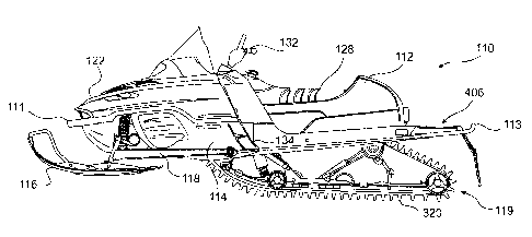
An embodiment of a snowmobile 110 embodying all aspects of the present
invention is
illustrated in FIGS. 2A and 2B. It should be noted that the snowmobile of
FIGS. 2A and 2B is
an embodiment intended to illustrate all aspects of the present invention and
is not provided for
the purposes of limiting the scope of the present invention to the snowmobiles
having exactly all
the components of the snowmobile illustrated in FIGS. 2A and 2B. For example,
a snowmobile
lacking one of the elements of the snowmobile shown in FIGS. 2A and 2B, such
as the tunnel
extension 406 described more, fully below, still can be in accordance with
another aspect of the
present invention, such as the track pattern described more fully below.
The parts common to the snowmobiles shown in FIGS. 1A, 1B, 2A and 2B, have
been
designated with same reference numerals with the parts belonging to an
embodiment of the
snowmobile. The parts of the snowmobile in FIGS. 2A and 2B different than the
parts of the
CA 02456088 2004-02-18
snowmobile in FIGS. 1 A and 1 B are detailed in the following description of
the invention, and
no other material modifications are contemplated.
Preferably, the snowmobile shown in FIGS. 2A and 2B has a 700 cc engine, and
the
inventors prefer a cylinder-reed-induction Series 3 Rotax twin engine, traded
under the
S trademark Rotax Engine Type 693 by Bombardier Inc. of Canada. Further, the
platform for the
snowmobile shown in FIGS. 2A and 2B is preferably a lightweight chassis that
provides lower
and rearward engine mounting, more preferably a chassis marketed under the
trade name of ZX
Chassis manufactured by and available from Bombardier Inc. of Canada. The ski
stance of the
inventors' preferred embodiment is 37 inches.
A. A Mountain Snowmobile With a Long Length Track
In accordance with an aspect of this invention, a preferred embodiment of a
mountain
snowmobile illustrated in FIGS. 2A and 2B has a track 320 whose length is 151
inches.
Previously, available mountain snowmobiles all used a track whose length was
no greater than
141 inches, by the virtue of the 136 inch mountain snowmobiles available from
the
manufacturers and 141 inch track for mountain snowmobiles available in the
aftermarket. Thus,
the present invention advantageously provides a mountain snowmobile with a
track having a
length greater than 136 inches as well as greater than 141 inches. Preferably,
the mountain
snowmobile in accordance with the present invention has a track length of 151
inches. A track
length is defined as the circumferential length of the endless body of the
track.
A track for a mountain snowmobile is distinguishable from tracks for
snowmobiles of
other categories in that the height of the profiles is greater than 1 %4
inches, preferably between
11
CA 02456088 2004-02-18
about 1'/4 and 2 inches. More preferably, the height of the profiles is
between about 13/4 inches
and 2 inches.
With the increased track length, there is a greater track surface to contact
powder snow
and thus, the flotation of the snowmobile is greatly enhanced in comparison
with the previously
available mountain snowmobiles. Further, with the added track length, the
mountain
snowmobile in accordance with present invention provides greater traction. At
the same time,
with a unique and novel track design, the present invention provides an
acceptable degree of
steerability despite increased track length, contrary to the conventional
wisdom of many in the
industry.
The preferred embodiment shown in FIG. 2 has a sixty pitch track. In the prior
art, the
snowmobile tracks have had 54 pitches for the 136" tracks and 56 pitches for
the 141" tracks.
The 151" track of the preferred embodiment of the present invention
accommodates sixty
pitches. A sixty pitch track can advantageously accommodate 10 six-pitch tread
patterns, 15
four pitch tread patters, 20 three-pitch tread patterns, or 30 dual pitch
tread patterns -- thus any
multiples of the traditional, the dual, or three-pitch tread patterns. In the
preferred embodiment;
a six-pitch tread pattern is used to optimize the track performance
characteristics, as discussed
more fully later. Because sixty pitches can accommodate multiples of both dual
and three-pitch
tread patterns, the 151 inch track of the preferred embodiment offers more
flexibility in the track
design than the 141 or 144 inch tracks. Further, because the width of the
tracks for mountain
snowmobiles is typically 15 inches, the 151 inch track can also be expressed
as having a nominal
length to a nominal width ratio of about 10.067, whereas the conventional 136
inch track has the
length to width ratio of about 9.067 and the 141 inch track has the length to
width ratio of about
9.400.
12
CA 02456088 2004-02-18
Although the preferred embodiment provides a mountain snowmobile having a
sixty
pitch track or a 151 inch track length, it is emphasized that the present
invention is not limited
thereto. For example, the invention should be broadly construed to include
tracks for mountain
snowmobile applications, (i.e. having a lug height of greater than 11/4
inches), having a track
length greater than the conventional 136 or 141inches, specifically including
the 144 inch tracks.
The 141 inch track is a 56 pitch track with the length to width ratio of about
9.40. The 144 inch
track is a 57 pitch track with the length to width ratio of about 9.60. The
principles of the present
invention in providing a mountain snowmobile with a 151 inch track can be
applied to mountain
sleds with tracks with lengths greater than 141 inches including 144 inches.
It should be further noted that 136 inches, 141 inches, 1.44 inches and 151
inches in
describing the track length are not absolute exact measurement, but rather
there are negligible
deviations in the measurements. For example, the 151 inch track is actually
closer to 151.2
inches.
B. Track Profile
In FIG. 3, a portion of the track illustrated in FIG. 2A is illustrated. The
track 320 is
fabricated as a molding of fabric reinforced natural or synthetic rubber. The
track is made from
ply rubber in the preferred embodiment. Embedded in the molded rubber body 321
is a plurality
of disposed reinforcing rods 328 (see FIG. 5A), each of which extend
transversely substantially
covering the entire width of the track. As illustrated in FIG. 4, the embedded
reinforcing rods
328 are embedded in the body with a regular spacing in longitudinally
extending rows. In the
preferred embodiment, between two successive longitudinally extending rows is
about 2.52
inches. Each horizontally extending reinforcing rod embedded area defines a
pitch.
13
CA 02456088 2004-02-18
FIGS. 5A and SB illustrate how the reinforcing rod 328 is embedded in relation
to the
projecting profile 3~4e and the inner lug 318, the relationship between which
is conventional and
well known in the art. By virtue of its construction, the rubber body 321 is
flexible in its
longitudinal direction, and it is stiffened in the transverse direction by the
series of regularly
spaced reinforcing rods 328 that extend along substantially the entire width
of the track,
preferably extending along the entire width of the track. The thickness of the
track is locally
increased in the region of the reinforcing rod embedded area 329 as is evident
in FIGS. 5A, SB
and 6. The track body 321 has two longitudinally extending areas corresponding
to the sprocket
engaging areas 323a, 323b of the track, as shown in FIGS. 3 and 7. On every
third pitch, the
reinforcing rod receiving areas 329 along the sprocket engaging areas 323a,
323b are preferably
reinforced by metal clips 330 of generally C-shaped profile. The ends 330a of
the metal clips 330
are clinched into the outer side of the track whereas the central portion 330b
lie flat against the
interior side of the track body 321 and form bearing means for engagement with
the slide rails of
the slide suspension, as is well understood in the art.
The outer side of the tracks has a pattern of projecting lugs, integrally
formed thereon.
The lugs are also referred to ws profiles, paddles or ribs, and therefore,
these terms will be used
interchangeably hereinafter in this application. The profiles are made of
fabric reinforced natural
or synthetic rubber. The durometer of the compound for the outside cover of
the track body 321
may range between about 60° and 80°. The durometer for the
compound for the inside cover of
the track body 321 and the lugs is about 80° durometer.
The profiles are discussed in further detail with reference to FIG. 3. In
general, however;
the profiles are provided on the reinforcing rod embedded areas 329 defined on
the endless body
321. The presence and absence of the profiles along the transverse direction
of a pitch define a
14
CA 02456088 2004-02-18
pitch pattern for that pitch. The profile pattern formed,by a particular
arrangement of successive
pitch patterns that repeats identically on over the successive pitches defines
a tread pattern. The
tread pattern is repeated identically on successive pitches on the endless
track body. The
repeated tread patterns in the successive pitches along the substantial length
of the track defines
the track profile pattern, also referred to as track pattern herein,
Conventionally, tread patterns based on two pitches or three-pitches have been
used in
the tracks for snowmobiles. A tread pattern formed based on the repetition of
the pitch patterns
of two successive pitches is called a dual pitch tread pattern. A tread
pattern formed based on
the repetition of the pitch patterns of three successive pitches is called a
three-pitch tread pattern.
For clarification, it is noted that the tread pattern is characterized and
defined by the lowest
number of the successive pitches comprising the pattern which repeats itself
For example, it can
be argued that a set of twelve successive pitches, which is formed by four
sets of the three-pitch
tread patterns, has a six-pitch tread pattern. Such argument would be contrary
to the definition
herein. Because the lowest number of successive pitches forming a pattern
which repeated itself
on successive pitches is three, the proper characterization of the tread
pattern in this example is a
three-pitch tread pattern, and not a six-pitch tread pattern. The definition
of tread pattern
provided and illustrated herein shall be applicable to the appended claims
also.
The preferred embodiment illustrated in FIG. 3 has a six-pitch tread pattern,
i. e., a tread
pattern formed based on the repetition of the pitch patterns of six successive
pitches. To
facilitate the discussion of the preferred embodiment illustrated in FIG. 3,
it is helpful to describe
the locations of the profiles along the longitudinal and transverse directions
of the track 320.
Along the longitudinal direction of the track 320, there are illustrated six-
pitches: a first pitch
331, a second pitch 332, a third pitch 333, a fourth pitch 334, a fifth pitch
335, and a sixth pitch
CA 02456088 2004-02-18
336. Along the transverse direction of the track 320, the track 320 is divided
roughly into five
lateral portions for discussion purposes: a left outer lateral portion A, a
left inner lateral portion
B, a central portion C, a right inner lateral portion D, and a right outer
lateral portion E. Thus, in
the six-pitch tread pattern illustrated in FIG. 3 comprises the following
profiles:
~ the first pitch 331 has profiles 341a and 341d;
~ the second pitch 332 has profiles 342b and 342e;
the third pitch 333 has profiles 343a and 343c;
~ the fourth pitch 334 has profiles 344b and 344e;
~ the fifth pitch 335 has profiles 345a and 345d; and
~ the six-pitch 336 has profiles 346c and 346e.
Likewise, the profile-free regions can be designated as follows:
~ the first pitch 331 has profile-free regions 341b, 341c and 341e;
~ the second pitch 332 has profile-free regions 342a, 342c and 342d;
the third pitch 333 has profile-free regions 343b, 343d and 343e;
~ the fourth pitch 334 has profile-free regions 344x, 344c and 344d;
~ the fifth pitch 335 has profile-free regions 345b, 345c and 345e; and
~ the six-pitch 336 has profile-free regions 346a, 346b and 346d.
It should be understood from FIG. 3 that the numerical designation is for
discussion
purposes only. Having common designation of the location along the traverse
direction of the
track does not indicate that they are identical in shape and the precise
location. For example, the
shapes and the locations of the profile 343c and the profile 346c along the
longitudinal direction
are not exactly the same although they are both designated as being disposed
in the central
portion C. Further, it is worth stressing in the beginning of the discussion
of the tread pattern
16
CA 02456088 2004-02-18
shown in FIG. 3 that the tread pattern shown in the FIGS. 3-7 is meant to be
illustrative of the
inventive concepts of the present invention, and not to limit the scope of the
invention by
providing a detailed description of the preferred embodiment of the inventors.
For example, the
locations, shapes and the number of the profiles on each pitch can be varied
easily without
departing from the spirit of the present invention.
The following observations are made regarding the tread pattern and the
profiles
illustrated in FIGS. 3 and 7:
1. There is no "open window," defined and discussed below, extending in the
longitudinal direction. In other words, when a tread pattern is viewed in the
longitudinal direction, (as is seen in FIG. 4), no profile-free area extends
all the way
to the next tread pattern. Thus, there is no profile free area along the
entire width of
the track;
2. The paddles or lugs on the outer lateral portions A and E of the track are
provided in a
"staggered" relationship in the longitudinal direction, wherein only one
paddle is
provided every other pitch on each of the outer lateral portions A and E.
3. The thread pattern of the track illustrated in FIG. 3 is a six-pitch
pattern, which is the
inventors' preferred tread pattern in the preferred sixty-pitch track;
4. The profiles along the width of the track have different heights, such as
in the
preferred embodiment which shows that the height of the portions of the
profiles just
inside of the two sprocket engaging areas 323a and 323b is lower than the
height of
the portions of the profiles outside of the two sprocket engaging areas 323a
and
323b;
17
CA 02456088 2004-02-18
5. Each of the profiles immediately adjacent to and inside the sprocket
engaging areas
323a and 323b have two portions having a different height than the others and
are
disposed with a slanted step-down area therebetween. For example, as shown in
FIG.
4, the profile 341d has a higher portion 364 and a lower portion 366 with a
slanted
step-down area 362. The higher portion 364. has a height of preferably 2
inches, and
the lower portion 366 has a height of preferably 13/4 inches. There is
provided a tower
portion 368 in the higher portion 364 immediately before the step-down area
362. At
the lateral ends of some profiles, there are provided slopes extending from
the track
body surface to the upper edge surface of the profiles. For example, the
profile 341d
has a slope 370 extending from the upper edge surface 372 of the profile 341d
down
to the track body surface 321; and
6. The profiles in the central portion C of the track are provided every third
pitch, and
are slightly offset from the center.
The above list of observations is not an exhaustive list and therefore should
not be viewed as
excluding other features of the present invention illustrated in FIGS. 3, 4
and 7.
We discuss the above noted observations with respect to various aspects of the
present
invention in turn. First, although there are profile-free regions in each
pitch, there is no
continuous line of profile-free areas in the longitudinal direction of the
track. As would be
appreciated by one skilled in the art, it is desirable that absent a
compelling reason, paddles
within a tread pattern leave no profile-free regions along the entire width of
the track. If such an
"open window" in the track exists when viewed in the longitudinal direction of
the track, the
snow is not cleared from under the track by any of the profiles. The snow left
along the track
18
CA 02456088 2004-02-18
line lifts the aft end of the snowmobile, creating a bobbing action, and
ultimately unstable and
rough ride of the snowmobile.
Thus, viewed in the longitudinal direction, a plurality of profiles along the
pitches of the
track should completely cover the transverse width of the track. For example,
in FIG. 3, in a
view taken from line IV-IV, any portions of the first pitch 331 that are the
profile-free regions
341b and 341e have profile in other pitches further down in the longitudinal
direction, the profile
342b. 342e for example. In the preferred embodiment, an entire width of the
track is covered in
the transverse direction by the profiles from at most three successive
pitches. In the example
above, all areas of the profile-free regions 341b and 341e of the first pitch
331 are compensated
with the profiles 342b and 342e from the second pitch 332. In another example
from FIG. 3, all
areas of the profile free regions 342a and 342d of the second pitch 332 are
compensated by the
profiles 343a and 343c of the third pitch 333 and the profile 345d of the
fifth pitch 335.
In another aspect of the present invention, every profile in one pitch in the
outer lateral
portions A and E is followed by a profile-free region in the very next pitch
in the longitudinal
direction. Thus, there is one profile every other pitch along the longitudinal
direction in the outer
lateral portions A and E of the track. This is defined herein as a staggered
relationship. For
example, the profile 341a in the first pitch 331 is followed by the profile-
free region 342a in the
second pitch 332, which is in turn followed by the profile 343a in the third
pitch 333. Likewise,
the profile-free region 341e in the first pitch 331 is followed by the profile
342e in the second
pitch 332, which is in turn followed by the profile-free region 343e in the
third pitch 333. This
one profile every other pitch along the outer lateral portions of the track is
repeatedly preferably
throughout the track.
19
CA 02456088 2004-02-18
The one profile per every other pitch arrangement in the longitudinal
direction
advantageously provides a better distribution of load per profile, in
comparison with a tread
pattern which places profiles in successive pitches in the longitudinal
direction. For example, in
the tread pattern shown in FIG. 1 l, there are substantially overlapping
profiles in the longitudinal
direction. For example, about 50% of the profile 541 a of the first pitch 531
is overlapped in the
longitudinal direction by the profile 542b of the second pitch 532. As another
example, 100% of
the profiles 543a and 543e in the third pitch 533 of the tread pattern shown
in FIG. 1 l, are in line
with, and therefore overlap, the profiles 544a and 544e of the fourth pitch
534.
When two paddles are provided in successive pitches along the longitudinal
direction, the
second of the paddle becomes "unloaded" because there is less snow for it to
grip. In such case,
the load on the second paddle located right after the first paddle in the
longitudinal direction is
substantially less than the first paddle in the tracking direction. Hence,
there is a inefficiency
associated with the latter paddle placed in a consecutive sequence. Had the
second paddle been
provided more snow to engage, it would have contributed more to the traction
provided by the
1 S track.
In contrast, when only one profile is provided in every other pitch in the
longitudinal
direction, the load on the two paddles, spaced apart by two pitches, tends to
be substantially
equal, thereby resulting in more balanced loads per paddle. Further, because
each paddle is
allowed to grip more evenly distributed snow, more traction force can be
generated. Thus, by
wasting less of the track driving force; the present invention advantageously
provide better
traction force.
For the mountain snowmobiles, the sled often performs ''sidehilling," during
which the
sled climbs a hill by making a plurality of diagonally upward zigzag moves.
During sidehilling,
CA 02456088 2004-02-18
one lateral side of the track contacts more of the snow surface than the other
due to the angle of
the sled's contact with the sidehill and the consequent weight transfer.
Therefore, the profiles on
the lateral ends in the transverse direction of the track are relied upon more
heavily to provide
traction. Obviously, any loss of traction abilities in the lateral portions
should be avoided. The
tread pattern illustrated in FIG. 3 in accordance with the present invention
advantageously allows
the profiles placed in the staggered relationship between pitches on the side
portions of the tracks
to perform better by providing more traction.
In another aspect of the present invention, the tread pattern shown in FIG. 3
is a six-pitch
tread pattern. The tread patterns available heretofore were either a three-
pitch tread pattern or a
dual pitch tread pattern. In the three-pitch tread pattern, three pitches
define the tread pattern to
be repeated identically on successive threesomes of pitches substantially
throughout the length of
the track, as shown in FIG. 11. In the dual pitch tread pattern, two pitches
define the tread
pattern to be repeated identically on successive twosomes of pitches
substantially throughout the
length of the track, as shown in FIG. 12. In contrast, the tread pattern of
the present invention
illustrated in FIG. 3 provides a six-pitch pattern, which repeats identically
on successive
sixsomes of pitches.
The track 320 of the preferred embodiment has sixty pitches and a track length
of 151
inches. Although the inventors prefer the number of pitches in the track be a
multiple of six, e.g.,
60 pitches, the present invention is not limited thereto. For example, because
the inventive
aspects of the six-pitch track pattern illustrated in FIG. 3 provide what the
inventors believe is
optimum track performance for the requirements of mountain snowrnobiling, one
could even use
multiples of six-pitches as much as possible and fill in the remaining pitches
with any pitch
patterns of the tread pattern. For example, if one were to opt for a track for
mountain
21
CA 02456088 2004-02-18
snowmobile having a length of 144 inches and 57 pitches, one can provide nine
repetitions of the
six-pitch tread patterns and provide the pitch patterns of the first three
pitch patterns, e.g. pitch
patterns of 331, 332, and 333.
The six-pitch tread pattern in accordance with the present invention is
advantageous over
the three-pitch pattern because the three-pitch pattern cannot accommodate the
one paddle every
other pitch in the longitudinal direction arrangement discussed above. If a
tread pattern repeats
after every three-pitches, there will be at least one pair of paddles per the
three successive pitches
that is lined up consecutively in the longitudinal direction, given design
parameters of
snowmobile tracks. The present invention, however, is able to accommodate the
one paddle per
every other pitch in the longitudinal direction arrangement as shown in FIG.
3.
Dual pitch tread patterns, on the other hand, can accommodate the one paddle
per every
other pitch in the longitudinal direction arrangement. However, the dual pitch
tread patterns
have inferior weight distribution than three-pitch tread patterns and the six-
pitch tread pattern of
the present invention. In short, the percentage of the weight of the profiles
in each of the first
and the second pitches are roughly 50% in the dual pitch tread pattern. The
three-pitch tread
pattern, on the other hand, can reduce the weight per profiles in each of the
three-pitches to about
33%. Thus, the weight of the sled can be reduced substantially since the lug
weight typically
comprises about 75% of the total weight of the track. One skilled in the art
would appreciate that
it is highly desirable to make the snowmobile as light as possible within
given design parameters.
This aspect is best explained by analyzing the weight of the paddles in any
given three
successive pitches. As mentioned earlier; an effective and efficient tread
pattern design leaves
no profile-free area over the entire transverse width of the track when viewed
in the longitudinal
direction. In the dual pitch tread pattern, the profiles over two pitches must
provide the coverage
22
CA 02456088 2004-02-18
for the entire transverse width of the track. In contrast, the three-pitch
tread pattern has, by
definition, three-pitches to provide enough profiles to cover the entire
transverse width of the
track. The optimum weight of the paddles required to cover the entire width of
the track is the
same, whether the paddles are in a two pitch tread pattern or in a three-pitch
tread pattern,
because the entire transverse width of a track can be covered using what would
be equivalents to
paddles that are all placed in one pitch.
For the purposes of comparison, the weight of the paddles necessary to cover
the entire
width of the track is assumed as 1.00 kg. It is further assumed that the
profiles of the dual pitch
pattern and the three-pitch pattern have been optimally arranged. Thus, in the
dual pitch pattern,
the entire width of the track is covered by the paddles over two pitches,
collective weighing 1.00
kg. In the three-pitch pattern, the entire width of the track is covered by
the paddles over three-
pitches, collective weighing 1.00 kg. Therefore, when the weight of the
optimally disposed
paddles per pitch is calculated, the weight of the optimally disposed paddles
per pitch in the dual
pitch tread pattern is 0.50 kg, while the weight of the optimally disposed
paddles per pitch in the
three-pitch tread pattern is 0.33 kg. Thus, when comparing the weight of the
optimally disposed
paddles in the dual pitch tread pattern over the same number of pitches with
the weight of the
optimally disposed paddles per pitch in the three-pitch tread pattern, the
weight of the paddles in
the dual pitch pattern is 50% greater than that of the three-pitch system. For
example, over the
three-pitches, the weight of the optimally disposed paddles per pitch in the
two-pitch tread
pattern is 1.50 kg. In the three-pitch tread pattern, the weight ofthe
optimally disposed paddles
per pitch in the three-pitch tread pattern is 1.00 kg. Thus, the weight of the
paddles in a track
using optimally designed three-pitch pattern is 2/3 of the weight of the
paddles in a track using
23
CA 02456088 2004-02-18
optimally designed two-pitch pattern. One skilled in the art readily agree
that the three-pitch
tread pattern achieves better weight distribution than two-pitch tread
patterns.
Returning to the six-pitch track profile of the present invention illustrated
in FIG. 3, the
tread pattern can be viewed as two three-pitch patterns whose second three-
pitch pattern is an
inverted image of the first. Thus, the advantages of the three-pitch patterns
over the two-pitch
pattern discussed above are equally applicable to the six-pitch tread pattern
illustrated in FIG. 3.
Further, the six-pitch pattern shown in FIG. 3 is more preferable to the three-
pitch pattern
because it allows the one paddle per every other pitch
°'staggered'° relationship on the outer
lateral portions of the track. The six-pitch tread pattern of the present
invention is also preferable
to the dual pitch tread patterns since it can achieve better weight
distribution. In fact, quite
surprisingly, the weight of the preferred embodiment of the track having a 151
inch length
illustrated in FIG. 2A has about the same weight as the weight of the track
with three-pitch
pattern having a 136 inch length illustrated in FIG. 1A.
There are several other reasons for this improved result of the track of the
present
invention having the reduced weight per same unit of track length in the
present invention. First,
it is noted that the lugs have been provided in a six-pitch pattern optimizing
their placement
along the transverse direction. Using the advantages of the three-pitch
pattern over the two-pitch
pattern, the profile-free regions are compensated over three successive
pitches, although on some
occasion the compensation is completed in two successive pitches. Second, the
staggered
relationship of the lugs on the outer lateral portions of the track reduces
the incidents of unloaded
paddles stemming from lugs provided on successive pitches along the
longitudinal direction.
Thus, each paddle is relied upon for a more balanced load, and the profile
pattern of the present
invention eliminates the inefficiency associated with the unloaded paddles.
Third, some paddles
24
CA 02456088 2004-02-18
have slopes like the slope 370 of the profile 341d shown FIG. 4. Because less
mass is provided
than having a block shaped paddle, the total weight of that paddle is reduced.
Fourth, as
discussed below, the height of the middle section of the track along the
transverse direction is
reduced and therefore weighs less.
Indeed, the tread pattern shown in FIGS. 3 and 4 has a further novel
characteristic in that
the height of the profiles of the track is not uniform throughout the track,
as more clearly shown
in shown in FIG. 4. Generally, in this "hybrid height" arrangement, the height
of the profiles at
the lateral ends of the track is higher than the height of the profiles at the
center of the track,
when viewed in the longitudinal direction. Preferably; the height of the
profiles remain at the
highest from the lateral ends toward where the idler wheels contact the inner
side of the track.
In FIG. 4, an elevation view of the profiles 341a and 341d is illustrated. As
can been
seen in FIG. 4 viewed in conjunction with FIG. 3, the height of the profiles
on the outer lateral
portions A and E of the track is constant and is higher than the height of the
profiles on the
central portion of the track. The profiles in the inner lateral sides of the
track has both the higher
height of the profiles on the outer later portion A and E and the lower height
of the profiles on
the central portion C of the track. In other words, each of the profiles
immediately adjacent to
and inside the sprocket engaging areas 323a and 323b have two portions having
each having a
different height than the other with a slanted step-down area 362.
For example, the profile 341 a of the outer lateral portion A of the first
pitch 331 has a
height of H, which remains constant. The profile 343c of the central portion C
of the third pitch
333 has a height of H2, which also remains constant. As shown in FIG. 4, the
profile 341d of the
inner lateral portion D of the first pitch has three portions -- a higher
portion 364 having a height
of H2 and a lower portion 366 having a height of HI with a slanted step-down
area 362
CA 02456088 2004-02-18
connecting the two portions. It is preferable that the step-down areas of the
profiles the inner
lateral portions B and D be placed on the inside of the areas which contacts
the idler wheels on
the inner side of the track.
In FIG. 4, there is illustrated a tower portion 368 in the higher portion 364
of the profile
341d, provided immediately before the step-down area 362 of the profile 341d.
The tower
portions provide reinforcement to the paddles and are located on each of the
paddles. At the
lateral ends of some profiles, there is provided slopes extending from the
track body surface to
the upper edge surface of the profiles. For example, the profile 341d has a
slope 370 extending
from the track body surface 321 to the upper edge surface 372 of the profile
341 d.
The overall effect of having Hl on the lateral outer portions and H2 on the
central portions
is that the hybrid height arrangement advantageously improves various
performance
characteristics of the track. First, the hybrid height profile arrangement
provides improved
floatability. Because the height of profiles toward the middle portion of the
track is lower, these
profiles engage less snow than the profiles on the lateral sides. Hence, when
the snowmobile
with the track moves, there will be more snow left under the track in the
middle portion than the
lateral portions. Accordingly, while the snowmobile would tend to assume a
position deeper into
the snow in the lateral portions, the more snow left in the middle portion of
the track aids the
flotation of the snowmobile through the powder snow.
Second, the hybrid height profile arrangement assists in addressing the
concerns over
"pushing" where the snowmobile tends to loose a significant measure of
steerability. The
concern over pushing is particularly more acute in mountain snowmobiles having
an extended
long track length, such as greater than 141 inches. When the height of the
paddles are reduced
from 2 inches to 134 inches, the paddles with the reduced height will provide
less traction. Thus,
26
CA 02456088 2004-02-18
the inventors have found that the excessive traction force of the long length
tracks can be
decreased by reducing the height of the middle portion of the track only. In
this way, the hill
climbing or sidehilling capabilities provided by the two inch lugs on the
outer lateral side of the
track is substantially maintained.
On a related note, to further address the concerns over pushing, the profiles
on the central
portion C of the track have been provided so that they will repeat every third
pitch. Inventors
have found that it is desirable to have the lugs on the outer lateral portions
A and E of the track
provide as much traction force as possible to effectively provide the
necessary traction when the
weight of the sled and the rider is transferred laterally in sidehilling. At
the same time, the lugs
in the middle portion C can be unloaded and may not necessarily need to
generate as powerful
traction force as the lugs on the lateral ends of the track.
Therefore, the profiles on the central portion C, as shown in FIGS. 3 and 7,
are provided
every third pitch. For example, the profiles 343c in the third pitch 333 is
followed by the profile
346c in the sixth pitch 336. It can be further observed that the profiles
341a, 342e, 343a, 344e,
345a and 346e in the outer later ends A and E have substantially same lateral
width as profiles
343c and 346c in the center portion C, while the profiles 341d, 342b, 344b and
345d provided on
inner lateral portions B and D have comparably shorter lateral width. Thus,
the profiles on the
inner lateral portions B and D also contribute to alleviating concerns over
too much pushing.
In the preferred embodiment, the H2 is 2 inches, and Hlis 134 inches. These
parameters
can be easily changed to 134 inches for the higher portion and 1 %2 for the
lower portion. Yet even
further, the hybrid height arrangement can be advantageously utilized in
snowmobile
applications other than mountain snowmobiles. For example, the flotation of
any snowmobile
27
CA 02456088 2004-02-18
can be improved with the hybrid height system. Therefore, the range of heights
need not be
restricted to between about 11/4 and 2 inches.
The inventors have found that the combination of the six pitch tread pattern
and the
hybrid height profiles discussed above significantly improves the performance
characteristics of
a track. An example of such track was tested with a mountain snowmobile having
a track with a
nominal width of 15 inches and a nominal length of 151 inches. The height of
the lugs were
about 13/4 inches in the lower portion toward the middle of the track and 2
inches on the outer
lateral portions. Previously, when a 151 inch track with conventional tread
patterns was tried,
the snowmobile was pushed too much, and therefore, resulted in poor
steerability. To
compensate again the loss of maneuverability, the inventors have experimented
with various
tread patterns, including the six pitch, hybrid height tread pattern of the
present invention. When
the tread pattern illustrated in FIG. 2 was utilized, the inventors found that
the track provided an
acceptable degree of maneuverability even with the long 151 inch track with
two inch lugs on the
lateral portions of the track and 13/4 inch lugs in the middle was providing
increased traction.
With the elongated length, the track provided an excellent hill climbing
ability. Yet even more,
the inventors have found that the lifting aided by the additional surface area
of the long track and
the hybrid height lugs provides superior flotation of the snowmobile.
C. Tunnel Extension
Because the snowmobile in the present invention is designed to utilize a track
whose
length is increased from the conventional regular length track, it is
necessary to increase sizes of
certain parts of the snowmobile and make several modifications to accommodate
the added
length in the track. In FIG. 8, the rear suspension systems and the tunnels of
the snowmobiles
28
CA 02456088 2004-02-18
shown in FIGS. 1A and 1B are illustrated to show the modification made to
increase the track
length to 151 inches. FIG. 9A shows a suspension system 402, a tunnel 404, a
tunnel extension
406 and various parts comprising the suspension system, the tunnel, and the
tunnel extension of a
mountain snowmobile of the present invention. FIG. 9B shows a suspension
system 402', a
tunnel 404', and various parts comprising the suspension system and the tunnel
of a mountain
snowmobile of the prior art.
As shown in FIG. 8, the drive wheel 416 has been moved down and rearward
slightly,
and the rear idler wheel 410 has been relocated further back toward the aft of
the snowmobile in
comparison to the drive wheel 416' and rear idler wheel 410' of the prior art
snowmobile
illustrated in FIG. 9B. The locations of other inner idle wheels 417, 418 and
423 have been
altered slightly from their prior positions 417', 418' and 423'. Further, the
positions of rear shock
414 and rear arm 412 have been also modified slightly in light of the
increased length of the
track. In addition, the slide frame 425 of the present invention in FIG. 9A is
longer in axial
length than the slide frame 425' of the snowmobiles with the regular length
136 inch track in
FIG. 9B. These above mentioned modifications are viewed as well within the
skills of one of
ordinary skill in the art. Further, the present invention shown in FIG. 9A
contemplates addition
of optional inner idle wheels 420, 424, 426, which in themselves are not
necessary to practice the
present invention.
To accommodate the extra length of the track, the total tunnel length has been
extended.
Significantly, rather than designing a brand new longer tunnel far the
snowmobiles to
accommodate the added track length, an aspect of the present invention
provides a tunnel
extension 406 illustrated in FIGS. 10A and l OB.
29
CA 02456088 2004-02-18
The tunnel extension in accordance with this aspect of the present invention
is formed of
the same material as the tunnel. In the preferred embodiment illustrated in
FIGS. 10A and l OB,
the tunnel extension 406 is a flank formed aluminum. The tunnel extension is
shaped to form a
tapered end to give an integral appearance with the tunnel. The tunnel
extension comprises a top
panel 430, a rear panel 432 and two side panels 434 and 436 as shown in FIGS.
10A. As shown
in FIG. l OB, the tunnel extension is attached to the tunnel 404 with a
plurality of rivets andlor
bolts in a manner known to one of skilled in the art. The side panels 434 and
436 have flange
portions 438 and 440 that are configured for bolt and rivet connection to the
tunnel 404 as shown
in FIGS. 10A and l OB. Also as shown in FIGS. 10A and 10B, a substantially U-
shaped bumper
442 is connected to both the tunnel 404 and the tunnel extension 406 around
side panels 405 and
407 of the tunnel 404, the side panels 434 and 436 of the tunnel extension
406. The bumper 442
is connected to the side panels 445 and 406 of the tunnel and the side panels
434 and 436 of the
tunnel extension 406 by rivets and bolts. The bumper 442 also acts as a handle
with which the
snowmobile can be pulled when the sled gets stuck in snow.
The added length of the track could have been accommodated by building a new
longer
tunnel as known in the art. Rather than building another longer tunnel,
however, the present
invention provides a tunnel extension 406 which could achieve cost savings. In
other words, the
tunnel extension is advantageous whenever the length of tunnel needs to be
extended, but the
cost benefit analysis or other considerations indicates that a new design of a
longer tunnel is not
desirable. The tunnel extension can easily and advantageously provide the
extra length in the
tunnel.
While the invention has been described with reference to several preferred
embodiments,
it will be understood by those skilled in the art that various changes may be
made and
CA 02456088 2004-02-18
equivalents may be substituted for elements thereof without departing from the
spirit and scope
of the present invention. In addition, many modifications may be made to adapt
a particular
situation, component, or material to the teachings of the present invention
without departing
from its teachings as claimed.
31