Note : Les descriptions sont présentées dans la langue officielle dans laquelle elles ont été soumises.
.
CA 02456253 2004-O1-26
UNIDIRECTIONAL, ADJUSTABLE FLAP VALVES
Field of the Invention
The present invention relates to a valve for controlling the air pressure
within
a protected space defined by wall surfaces. More particularly, the invention
relates
to a flap valve to be used in a structure for preventing the penetration of
contaminated air and/or gases, liquids or aerosols, and for controlling air
pressure
within such a protected space.
Background of the Invention
As is known, there is an increasing need for protection against the
penetration
of contaminants into a sheltered space, given the threat of military attacks
and acts
of terror using nuclear, chemical or biological (NBC) means of warfare. Such
protection is provided by the use of shelters and protected spaces located
inside
buildings ("hard" shelters), or tent structures ("soft" shelters). Hard
shelters are
provided with professional N13C air filtration systems including blowers;
which
create an overpressure inside the protected space and provide cleaned and f
ltered
air. The overpressure is required in order to ensure a clear direction of
airflow from
inside the protected space to the outside atmosphere, through ever-present
leaks in
the walls of the shelter, the door and the window seals. Use of this method
makes
sure that no contaminated air will penetrate into the protected space.
In a typical soft-type shelter, clean, NBC-filtered air is pushed by blowers
into the tent, with excess air passing to the outside through leaks or
specially created
holes in the walls of the tent. The disadvantage of such an arrangement is
that,
during times when no fresh air is pumped into the protected space, e.g.;
during a
blower breakdown, the essential overpressure immediately drops, with two dire
results: contaminated air can enter the protected space via the air exit
holes, and, if
CA 02456253 2004-O1-26
0
2
the protected space is in fact an inflated structure, the internal liner
bubble may
collapse, trapping inside all of the persons and goods to be protected. If
these
structures had closable valves, none of the above failures would be able to
occur and
the system would remain intact for a prolonged period of time until the clean
air
supply resumes and creates the required overpressure.
Disclosure of the Invention
It is therefore a broad object of the present invention to provide both hard
and
soft protected shelter structures with valves for controlling air pressure
that are
reliable, inexpensive and easily installed.
It is a further object of the present invention to overcome the disadvantages
of the fresh-air supplied prior-art protected spaces and structures, and to
provide
such structures with valuing arrangements that will either act as safety
valves to
protect the space against excessive overpressure, or to close off the
protected space
in the event of an air supply system failure until sufficient pressure has
been rebuilt,
or to operate as simple non-return valves.
The terms "protected space" and "structures" used herein are meant to
encompass all types of such spaces and structures, including vehicles which
may
provide shelters against NBC attacks.
According to the invention, the above objects are achieved by providing a
flap valve for controlling the air pressure within a protected space defined
by walls,
said flap valve comprising a valve frame attachable to an opening made in said
walls, a valve flap, articulated at least indirectly to said frame and being
subjectable
to both a sealing force which forces said valve flap against said valve frame
and to
an opening force which lifts a portion of the flap off said valve frame; said
flap
valve having a first position in which said protected space is sealed off from
a
CA 02456253 2004-O1-26
3
contaminated environment, and a second position in which air from said
protected
space is allowed to escape into said environment via said opening; wherein
said
sealing force is constituted by at least one spring at least indirectly
attached to said
valve flap and said valve frame.
Brief Description of the Drawings
The invention will now be described in connection with certain preferred
embodiments with reference to the following illustrative figures, so that it
may be more
fully understood.
With specific reference now to the figures in detail, it is stressed that the
particulars shown are by way of example and for purposes of illustrative
discussion of
the preferred embodiments of the present invention only, and are presented in
the cause
of providing what is believed to be the most useful and readily understood
description
of the principles and conceptual aspects of the invention. In this regard, no
attempt is
made to show structural details of the invention in more detail than is
necessary for a
fundamental understanding of the invention, the description taken with the
drawings
making apparent to those skilled in the art how the several forms of the
invention may
be embodied in practice.
In the drawings:
Fig. 1 is a perspective outside view of a flap valve according to the present
invention, swivelling in an upward direction;
Fig. 2 is a perspective outside view of a flap valve according to the present
invention, swivelling in a downward direction;
Fig. 3 is a perspective inside view of a first embodiment of a flap valve
according to
the invention;
Fig. 4 is a cross-sectional view of the flap valve of Fig. 3;
CA 02456253 2004-O1-26
4
Fig. 5 is a perspective inside view of a: second embodiment of the flap valve
according to the present invention;
Fig. 6 is a plane inside view of the flap valve of Fig. 5, showing a first
state of
adjustment of the opening force, and
Fig. 7 is a plane inside view of the flap valve of Fig. 5, showing a second
state of
adjustment of the opening force.
Detailed Description of Preferred Embodiments
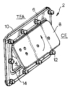
Referring now to the drawings, Figs. 1 and 2 illustrate a flap valve 2 for an
NBC-protected hard or soft structures (or shelters), which may be defined by
rigid
walls, semi-rigid walls, flexible walls, or a combination thereof, and is
prodded
with a window 4, in which the flap valve 2 is installed. By opening the valve
covering the window 4, any excess pressure can exit from the structure through
the
window from the toxic-free area (TFA) to the contaminated environment (CE).
The flap valve 2 is composed of a frame 6 and a flap 8. The frame is made
with flanges 10, whereby the frame is attached to the wall of the structure by
means
of bolts and nuts 12. If the wall is made of a plastic material, attachment
may be
effected by ultrasonic welding, or by other joining methods, e.g.; gluing.
As further seen in Figs. 1 and 2, the flap 8, which is hingedly coupled to the
frame 6, can be articulated to swing upwardly (Fig. 1 ) or downwardly (Fig. 2)
according to choice. The flap 8 and/or the frame 6 may advantageously be
furnished
with a sealing ring 14. The material from which the flap 8 is made is
predetermined
not only in consideration of strength and durability, but also in
consideration of its
own weight, as will be explained hereinafter:
A first eanbodiment of the articulation of the flap valve 2, seen in Fig. 1
for
controlling the air pressure within a protected space, is shown in Figs. 3 and
4. A
CA 02456253 2004-O1-26
S
U-shaped bracket 16, affixed to the valves frame 6, supports an axis 18. To
the
latter there is attached flap hinge elements 20. Two torsion spring sections
22 are
slipped over the axis 18, one end of each of the spring sections being
attached to a
flap hinge element 20, while the other end is attached to one side of a spring
torsion
adjustment revolving member 24 also mounted on the axis 18. Per-se known means
(not shown) for affixing the member 24 at a set angular position is also
provided.
A second embodiment of the flap valve 2 for controlling the air pressure
within a protected space, is illustrated in Figs. 5 to 7. Seen is the valves
frame 6, the
flap 8, as articulated to the frame 6 by means of the bracket 16, supporting
the axis
18 and the flap hinge elements 20. The adjustment of the pressure required to
move
the hinged flap 8 beyond its initial state as determined, inter alia, by the
force of the
spring 26 and the flap's own weight, is provided by a slider arrangement 28.
The
latter consists of a bent leaf spring 30 affixed at one end 32 to one side of
the flap 8,
while bearing against the flap 8 at its other end. A slider 34, coupled to,
and guided
by, a slot 36 made in the frame 6, can be manually slid along the leaf spring
30 from
one limit position near the leaf spring end 32 (Figs. 5 and 6), to an
intermediate
position (Fig. 7) and beyond to the other end of the leaf spring 30. At any
set
position a thumb screw 38 locks the slider to prevent its movement, thereby
determining the spring force applied to the flap beyond the initial force
applied by
the spring 26.
The valves according to the present invention thus have three modes of
operation:
a) Standard mode - wherein the valve is prefixed to a certain
overpressure valve, thereby the valve keeps a certain maximum
pressure in a protected space;
CA 02456253 2004-O1-26
6
b) Seal mode - in case of a blower problem or maintenance of the
filters/blowers, the valve can be used to seal the protected space, and
c) Protect mode - when blowers are started, the valve protects soft
shelters from bursting even when the valve is not set back from the
seal mode.
Since the valves of the present invention have the characteristics of
providing
constant overpressure, e.g., 300 to 320 Pa, it can be used in shelters and
vehicles, as
it opens only when the preset pressure value is reached and not earlier. Any
leakage
of the protected space is therefore limited to that of real leaks.
With the utilization of the embodiments described hereinbefore, the following
specific operation features can be achieved:
1. Valve 2 is opened against the force of torsion of a spring or springs until
completely open. The pressure in the space decreases by less than 10%. The
flap 8 has a rotation axis upwards (Fig. 1).
2. Valve 2 is opened against torsion spring(s), but the weight of the flap 8
compensates for the force of the spring, hence the pressure is constant. The
flap 8 has the rotation axis downwards (Fig. 2).
3. Valve 2 is opened against the torsion spring(s), however, the weight of the
flap 8 overcompensates the increase of the spring force. The valves open
completely at a certain pressure point, resulting in a pressure drop. The flap
8
has the rotation axis downwards.
CA 02456253 2004-O1-26
7
4. Valve 2 is opened against a bent spring 30 (Figs. 5 to 7) at a certain
pressure
with a constant increase of pressure, until it is completely open. The spring
force is selected as constant. The flap 8 can have a rotation axis upwards or
downwards.
5. Valve 2 is opened against a bent spring 30 at a certain pressure and is
opened
completely immediately. The spring force is selected as decreasing. The
flap 8 can have a rotation axis upwards or downwards.
6. Valve 2 is opened manually against the spring force by means of a slider
34,
to reach a certain pressure in the space and could be closed by the spring
force when the slider 34 is pushed back to the start position.
7. Combined feature (sealed and burst pressure protection) as in 6 above,
however, in the sealed condition, the valve 2 will be opened by an
overpressure (below the burst pressure but above the working pressure)
against the spring force, as described in points l to 5.
8. Combined features of sealed and regulated pressure - a predefined pressure
is
achieved by a manual change of the preset force of the torsion spring 16
(instead of the use of a slider). The opening of the valve 2 will occur when
the working pressure exceeds the setting of the spring force (features 1 to 5
above), and
9. With an additional spring 30 between the slider 34 and flap 8, the valve 2
could be used as a non-return valve (spring 7). Thus, a gust of wind would
close the valve and protect the inside from contamination. This will be
achieved with feature 8, without an additional spring.
CA 02456253 2004-O1-26
It will be evident to those skilled in the art that the invention is not
limited to
the details of the foregoing illustrated embodiments and that the present
invention
may be embodied in other specific forms without departing from the spirit or
essential attributes thereof. The present embodiments are therefore to be
considered
in all respects as illustrative and not restrictive, the scope of the
invention being
indicated by the appended claims rather than by the foregoing description, and
all
changes which come within the meaning and range of equivalency of the claims
are
therefore intended to be embraced therein.